OPERATORS
MANUAL
CGC 7900 SERIES
COLOR GRAPHICS COMPUTERS
· .-- -.-;" -...
CHROMATICS
CGC 7988 COLOR GRAPHICS COMPUTER SYSTEM
Operator's Manual TERMEM Version 1.4
Copyright (C) 1983 by Chromatics, Inc. 2558 Mountain Industrial Boulevard
Tucker, Georgia 38884
CHROMATICS
CGC 7900 SERIES COLOR GRAPHICS COMPUTERS
OPERATOR'S MANUAL
Document Number 070201B
Printed May, 1981
Copyright (C) 1981 by Chromatics, Inc.
2558 Mountain Industrial Boulevard Tucker, Georgia 30084
Telephone (404) 493-7000 TWX 810-766-8099
NO REPRODUCTIONS WITHOUT EXPRESS WRITTEN PERMISSION FROM CHROMATICS, INC.
WARNING
This equipment generates, uses, and can radiate radio frequency energy and if not installed and used in accordance with the instructions manual, may cause interference to radio communications. It has been tested and found to comply with the limits for a Class A computing device pursuant to Subpart
Conventions used in this Manual
1) Any keys which have labelled caps will be called by their full names, capitalized and underlined. For example, the carriage return key will be denoted by:
RETURN
2) The modifier keys, CTRL, SHIFT, Ml and M2, must be held down whil e str iking the key they are
To
modiTy. Note that these four keys do not generate any characters on their own, but simply modify the character which is struck simultaneously. This process of holding down a modifier key while striking another key will be denoted by the modifier AND the key beingunderlined together. For example,
CTRL F
would indicate that the CTRL key should be held down while striking the F key. If two or more modifiers are needed simultaneously, they will all be underlined together:
CTRL SHIFT T
would mean that BOTH modifiers, SHIFT and CTRL, should be held down while striking the T key.
----For keys marked with names for these modifiers (CTRL or SHIFT only), the modifier will not be specified. For example, the View Sub-buffer command is generated by holding down the SHIFT key and pressing the key marked REDRAW and VIEW1 this is represented as:
VIEW
(This is a change from the previous manual.) Functions wi thout names marked on the key are still represented by including the modifier. For example, the command to move the cursor to the lower left-hand corner of the window is represented as:
CTRL HOME
3) Variable parameters will be enclosed in angle brackets, < >. Any items enclosed in these brackets will be explained in full in the text which immediately follows.
4) Optional parameters will be enclosed in square brackets [ ]. Any items which may be repeated will be followed by an ellipsis (three dots).
Example of (3) and (4):
<X>, [ <Yl> , <Y2> , ••• ]
The parameter <x> is required. The parameters <Yl>, <Y2>, and so on, are optional. Any number of these may be included. All three types of parameters would be explained immediately beneath the example which contained them.
Table of Contents
Preface
Chapter 1 -- Introduction
CGC 7999 Overview •
Installation • • • • • • • • • • • • • • • • • • • •
Booting Software • • • • • •
Keyboard Description • • • • • • • • • • • • • • •
Codes and Code Sequences • • • • • • • • • • • • • • • • • Escape Code Sequences
User Code Sequences
Plot Code Sequences
· . .
. .
• • • • • • •Mode Code Sequences • • • • • • • • • • • • • • • • • • Code Hierarchy
System Error and Recovery Reset, Boot, Soft Boot Convergence and Degaussing
· . .
.
. . .
.
.
.
• • • • • • • • •
Chapter 2 -- The Overlay
·
. ·
. .
. .
• • • • • • •
Overlay Defaults • • • • • • • • • • • • • • • • • • • • • Overlay Operations • • • • • • • • •
Entering and Exiting the Overlay
Overlay Cursor Control • • • •
Overlay Cursor Blink ON/OFF
Overlay Roll and Page • • •
.
.
• • •
• • •
· .
.
. · .
.
. . .
.
• • • • • • • • • • •
• • • • • • • • • • •
Overlay Color and Blink • Set Foreground Color Set Background Color Overlay Blink ON
Overlay Blink OFF • •
· . .
.
. ·
.
.
.
. . .
.
. . . .
·
.
.
• • • • •
Modify Overlay Visible Attributes • Overlay Plotting Functions
Table of Contents
Chapter 3
•
Assigning Physical Devices Assign Output Device
Assigning Input Devices •
•
•
Systea COlUllands
• • • • • • • •
• • • • • • • •
• • • • • •
• • • • • •
Select Character Set
Delay • • • • • • • • • • • • • • • • • • •
Function Keys • • • • Bezel Keys
Defining Function
• • • • • •
Keys from a Host
• • • •
• • •
• • •
Light Pen •
Real-Time Clock • Set Clock Display Time
•
· . . .
. .
.
• • • • •
• • • • •
Test • • • • • • Tone Generator
Visible Control
Warm Start Characters
Windows • • • • • • •
Set Window Limits • •
• • • • •
• • • • •
• • • • •
• • • • •
• • • • •
Scale Factors (Virtual Coordinates) Scaling ON/OFF
Window and Scale • • • • • • •
• • • • • • • • • • • • • • • • • • • • • • • • • • • • • • • • • • • • • • • • • • • • • • • • • • • • • • • • • • • • • • • • • • • • • • • • • • • • • • • • • • •
Hardcopy • • • • • • • • • • • • • • • • • • •
Chapter 4 -- Terminal Emulator (TERMEM)
Restricted Terminal Emulator Local Mode
Half Duplex Mode • • • • • Full Duplex Mode
Keyboard Sync • • • • • • •
Serial Communications • • • Serial Port Connectors Recommended Serial Port Set Serial Baud Rate Set Serial Parity, Word
Reconfigure SPC Ports •
• • • • • • • • • • •
• • • • • • • • • • • • •
• • • • • • • • • • • • • •
• • • • • • • •
Wiring • • • • • • •
Length, Stop Bits • • •
Table of Contents
Chapter 5 -- The Create Buffer
Create Buffer ON • • • • • • • • • • • • • • • • • • • • • Create Buffer OFF
Append to Create Buffer • • • • • • • • • • • • • • • • • • Redraw the Create Buffer
Transmit the Create Buffer • • • • • • • • • • • • • • • • Define a Sub-Buffer
Insert into Sub-Buffer • • •
Kill a Sub-Buffer
.
.
.
. .
• • •.
.
View a Sub-Buffer • • • • • • • • • • • • • • • • • • • • • Literal Create
Chapter 6 -- Thaw and Me.ory Allocation
Thaw Parameters • • • • • • • • • • • • • • • Thaw Parameters for Idris
Default RAM Allocation • • • • • • • • • • •
· .
.
.
.
.
.
• • • • • • •
Chapter 7 -- Numerical Data and Window Variables
Numerical Data
. . .
.
.
. .
. .
. . .
Window Variables • • • • • • • • • • • • • • Operate on Window Variable
Display and Transmit Window Variables • • Window Variable Uses
· . . . .
.
.
·
. .
.
. . .
Binary Mode • • • • • • • • • • • • • •
Binary Mode (Escape Code Processor) • • • • • • • • • •
Table of Contents
Chapter 8 -- The Bitmap
Bitmap Defaults •
Bitmap Operations
.
.
. . . .
.
.
• • • • • • • • • • • • •Bitmap Blink • • • • • •
Blink ON • • • • • • • • •
Blink Off • • • • • •
Select Blink Plane(s) • • • • • • • • •
Set Bitmap Character Size • • • • • • Set Bitmap Intercharacter Spacing Load User-defined Character Set • Overstrike • • •
·
. .
• • • • • • • • • • • • • • • • • • • • • • • • • • • • • • • • 8-2 8-3 8-5 8-6 8-6 8-7 8-8 8-9 8-10 8-11Bitmap Color • • • • • • • • • • • • • • • • • • • • • • • 8-12
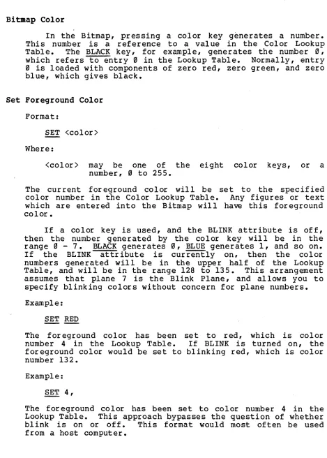
Set Foreground Color 8-12
Set Background Color • • • • • • • • • • • • • • • • • 8-13
Color Lookup Table 8-14
Modifying the Color Lookup Table • • • • • • • • • • • 8-17
Change Color Lookup Table Entry (RGB Units) 8-17
Change Color Lookup Table Entry (HVS Units) • • • • • • 8-20
Default Color Lookup Table 8-21
Color swap • • • • • • • • • • • • • • • • • • • • • • • 8-22
Colorset 8-22
Bitmap Cursor Control
Set Cursor Color • • • • • • • • • • • • • • • • • • • Fill Mode • • • • • • • • • • • • • • • • • • • • • • • • •
Complex Fill Algorithms
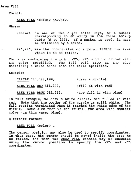
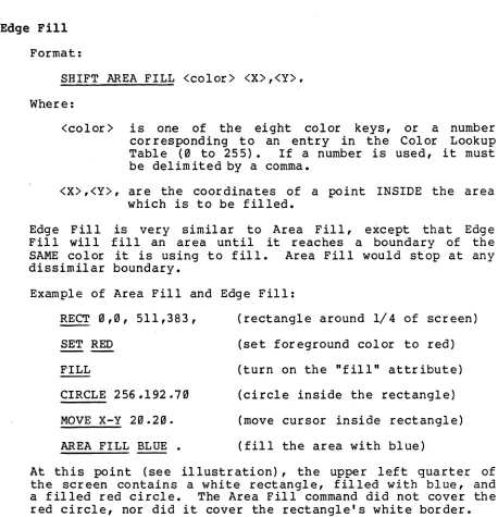
Area Fill • • • • • • • • • • • • • • • • • • • • • • • Edge Fill
Joystick • • • • • • • • • • • • • • • • • • • • • • • • • Pan and Zoom • • • • •
Absolute Pan
Absolute Zoom • • •
• • • • • • • • • •
·
~. . .
.
.
·
.
. . .
Bitmap Roll and Page
Rubber Band • • • • • • • • • • • • • • • • • • •
Table of Contents
Chapter 9 Plot SubDlodes
Arc • • • • • • • • • • • • • • • • • • • • • • • • • • • • Circle
Two-point Circle
Curve • • • • • • • • • • • • • • • • • • • • • Dot • • •
Incremental Incremental Incremental
• • • • • • • • • • • • • • • • • • • • • • •
Vector X-Bar •
Y-Bar • • • • • • • • • • • • • • • • • • • •
Polygon. • • • Large Polygons
Ray • • • Rectangle Triangle • • • • • • • • • • • • • • • • • • • • • • • • • • •
Vector • • • • • • • • • • • • Concatenated Vector
Bold Vector • • • • • • • • Concatenated Bold Vector Set Vector Width • • • • •
Vector-Drawn Characters • Exiting Plot Submodes • •
• • • • • • • • • • • • • • • • • • • • • • • • • • • • • • • • • • • • • • • • • • • • • • •
·
.
•·
.
• • • • • • • • • • • • • • • • • • •Chapter 18 -- Raster Processor Graphics
Define Source Raster
Copy Raster • • • • Copy Raster with Overstrike • Set Raster Direction
Patterned Vectors • • • • • •
• • • • • • • • • • • • • • • • • • • • • • • • • • • • • • • • • • • •
Chapter 11 -- Expanded Image Memories
Select Image • • • • • • • • Plane/Video/Blink Select
Writing to the Second Image • Plane Select
Plane Video Switch • • • • •
Table of Contents
Appendix A -- Special Codes
Control Codes • • • • Mode Codes
Plot Codes
Escape Codes • • • • •
•
•
•
User Codes • • • • • Command Reference List Key Sequences • • • • • Inline Editor Commands
• • • • • • • • • • • • • • • • • • • • • • • • • • • • • • • • • • • • • • • • • • • • • • • • • • • •
Appendix B -- Color Display Scheaes
The Color Cube
The HVS Hexcone • • • • • • • • • • • • • • • • •
Appendix C -- The Monitor
• • • • •
• • • • •
• • • • •
• • • • •
• • • • •
Monitor Operations
The Inline Editor • • • • • • • • • • • • • • • • • • • •
Monitor Commands
Abort • • • • • Change Memory • • • • • Checksum Memory
Compare Memory Disk Read
Disk Write Dump Memory • •
• • • •
• • • •
Evaluate Math Expression Examine Registers
Fill Memory • • • • • Go (with Breakpoints) Load. • • • • • Move Memory
Punch • • • End Punch Set Memory Trace •
• •
• • • • •
Trace Display • • • • • Virtual Search
• • • • • • • • • • • • • • • • • • • • • • • • • • • • • • • • • • • • • • • • • • • • • • • •
·
.
. .
• • • • • • • • • • • • •Appendix D -- Traps
Table of Contents
Appendix E -- Custom Modules, Cursors and Character Sets
Modules -- General
The Linking Process • • • • • • • • • • • • • • • • • • • • Module Construction 0 0 0 0 0 • • • • • • • • • • • • • • •
Boot Modules
Input/Output Modules 0 0 • • • • • • • • • • • • • • •
Argument Parsing
Register Setup for Modules • • • • • • • • • • • • • •
Mode Modules 0 0 0 0 0
Example Mode Module • • • • •
o • 0 0 0 0 • • • • • • •
Plot Modules 0 0 0 0 0
Example PLOT Module • • • • • • • • • • • • • • • • • •
Escape and User Modules 0 0 0 0
Example ESCAPE code Module • • • • • • • • • • • • • •
Window Tables 0 0 0 0 0 0 0 0 0 0 0 0 0 0
Window Status and ESCAPE Code Status • • • • • • • • •
Custom Character Sets 0 0 0 0 0 0 0
Vector-Drawn Character Format Algorithm Description 0 0 0 0 0
• • • • • • • • • • • •
. . .
.
E-2 E-4 E-5 E-6 E-7 E-9 E-ll E-12 E-13 E-14 E-16 E-17 E-18 E-19 E-22 E-23 E-26 E-28Installing a New Cursor • 0 0 0 0 0 0 0 0 0 0 0 0 0 0 0 0 0 E-3B
TERMEM Jump Tables E-33
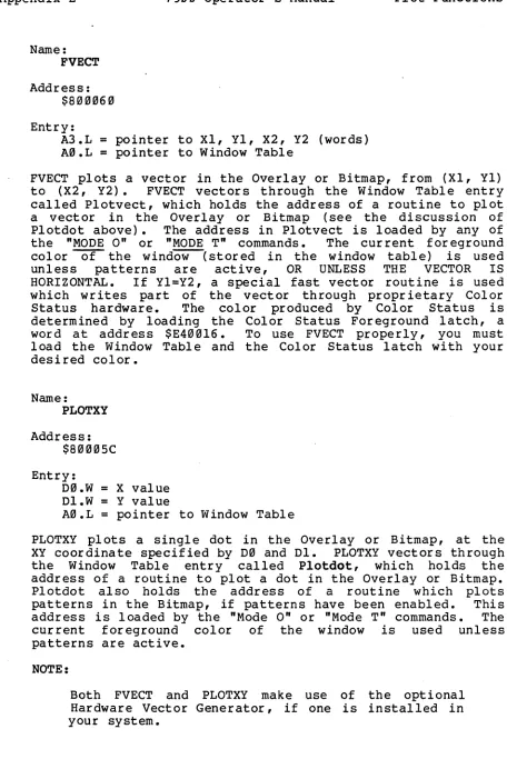
Plotting Functions 0 0 0 0 0 0 0 0 • • • • 0 • 0 0 0 • E-44
Inline Calling Sequences E-5B
Appendix F -- ASCII Codes
Standard ASCII Character Set • • • 0 0 • • 0
Preface 7900 Operator's Manual Preface
Preface
Bow to Use this Manual
If you are not familiar with any Chromatics products, read Chapter 1, Chapter 2, Chapter4 and Chapter 7 through Chapter 9. Appendix A will be a good reference as you continue to learn the system.
Once you have become familiar with the CGC 7900, you will want to read Chapter 3, Chapter 5, Chapter 6, Chapter 1B
and Chapter 11. The Appendices will also be helpful.
Advanced users will want to use this manual mainly as a supplement to the CGC 7900 Reference Card. The Reference Car d contains a compl ete 1 i st of CGC 7900 commands, and a very brief description of each one. This manual provides more detailed information.
Changes fro. the Previous Manual
The changes in this manual reflect in part the evolution of the 790 e. The manual has been completely reorganized to make it easier to read and to accommodate newer features. If you have the old 7900 manual, you may wish to skim through this one to note the differences.
• A new table lists CGC 7900 commands in alphabetical order, rather than by Mode, Plot, etc. Another table lists the codes generated by each key.
• Plot submodes, Raster Processor commands, Thaw parameters and other topics are now under their own chapter headings.
• Operating systems are discussed to a small extent.
• Descriptions of commands in the text are alphabetized where possible to make them easier to find.
Chapter 1 7900 Operator's Manual Introduction
Chapter 1 -- Introduction
This is the User's Manual for the Chromatics CGC 7900 Color Graphics Computer. It discusses how to operate the 7900. and gives examples of the system's capabilities. If you are just beginning to learn about the 7900, this is the first manual you should read.
This manual is divided into eleven chapters and six appendices:
Chapter 1 (this section) discusses the 7900 architecture. philosophy and installation.
Chapter 2 explains philosophy and commands for the Overlay.
Chapter 3 explains system commands which relate to the 7900 as a whole.
Chapter 4 discusses the Terminal Emulator (TERMEM).
Chapter 5 discusses commands for the Create Buffer.
Chapter 6 explains CMOS RAM and Thaw parameters.
Chapter 7 discusses numerical data entry and calculation.
Chapter B discusses Bitmap operations. These include color manipulation. Pan and Zoom. and cursor control.
Chapter 9 explains the various 7900 plot submodes.
Chapter 10 discusses Raster Processor commands.
Chapter 11 discusses commands for systems with sixteen image planes.
Appendix A lists commands alphabetically and by type.
Appendix B discusses color display schemes. Appendix C discusses the CGC 7900 Monitor.
Appendix D lists Trap codes.
Overview 7900 Operator I s Manual Chapter 1
CGC 7908 Overview
The CGC 7900 is the successor to Chromatics I CG series
of color graphics computers. Many of the same philosophies
have been retained in the development of the 7900, and a user who is familiar with the CG will quickly become accustomed to the 7900.
The 7900 contains at least three processors:
• Most system functions revolve around the MC68080
processor, selected for its high speed (8 megahertz)
and large memory addressing range (16 megabytes).
This powerful processor gives the 790e outstanding
capability for stand-alone computing applications.
And when the 7900 is acting as a terminal (connected to a host system), the 7900's power relieves the host of many of the tasks normally required in a graphics environment.
• The 790 fJ also includes a processor in the keyboard,
and a Raster Processor to provide high performance and speed in graphics operations.
•
Optionally, the 790fJ may containController with its own on-board Z-80
optional Hardware Vector Generator
considered a processor.
a Ser ial Port
processor. The
can also be
Many graphics systems suffer from one dr.awback: they
require a separate character-or iented terminal for command
level interact.ion between the system and the operator. The
7900 addresses this need by providing a character-oriented "Overlay" display in addition to the high-resolution Bitmap
graphics display. With eight standard colors and blink, the
Overlay is a very effective tool for operator interaction.
When not needed, the Overlay can become instantly
"transparent" to reveal high-resolution graphics images in the Bitmap.
The concept of logical and physical devices, used in the Chromatics CG series of computers, has been expanded and
applied to the 7900. All programs in the 7900 communicate
only through logical devices, which are numbered fJ through 4. 7900 software associates each logical device to one or more
physical devices. This association may be changed at any
time, allowing total flexibility in programmed input/output. Any program can accept input from any physical device, and
transmit output to any physical device. Some examples ·of
physical devices are the keyboard, the serial ports, and the 790e display screen.
Chapter 1 7999 Operator's Manual Overview
The screen can be subdivided into several distinct areas known as windows. Each window is a separate physical device (emulated by software). Thus. each window can be used for a separate purpose. and independent simultaneous displays are possible. In some applications. one 7909 could replace up to 16 separate terminals.
All 7999 features discussed in this manual, and most currently available optional features. are contained in a single stand-alone package. Standard features include:
• l28K or s12K bytes of buffer memory
• One or four planes of Bitmap image memory
• A keyboard with 151 keys (21 lighted) and 24 user-definable function keys
• 8 programmable bezel keys
• Two serial ports
• 19-inch color display screen with 1024 x 768 resolution
• A PROM firmware package which allows easy control of all system functions.
Optional features currently include:
• Lightpen and joystick for interactive use
• A battery-backed Real-Time Clock and CMOS memory
• Disk Operating System (DOS) much like that of the CG
series
---• Floppy and hard disk drives
• Idris Multi-tasking Operating System
• A Hardware Vector Generator (HVG) which can draw up to 27.099 short vectors per second
Overview 7988 Operator's Manual Chapter 1
• Parallel Input/Output and Direct Memory Access Interface
• Serial Port Controller (SPC) with 4 RS-232 ports
• Disk DMA (with Idris and DOS drivers available)
• Numerous peripheral interfaces
• Language support (FORTRAN, C, Pascal)
Chapter 1 7999 Operator's Manual Installation
Installation
Unpack the CGC 7999 according to the instructions supplied in the shipping carton. Retain the packing material so that it may be used for shipping the 7999 in the future.
WARNING:
If your 7999 system includes the optional Fixed Disk drive, REMOVE the locking screw and actuator lock which was used to secure the drive during shipment! See instructions on your unit for details. FAILURE TO REMOVE THESE LOCKS WILL DESTROY THE HARD DISK, AND VOID YOUR WARRANTY!
Connect the 7999 power cord to a power source of 119
volts AC, 69 hertz (229 VAC, 59 hertz optional), capable of supplying at least 19 amperes. For reliable operation, power should NOT come from a circuit with any heavy motors or industrial equipment connected which could create transients on the power lines. This includes equipment such as refrigerators and air conditioners.
The 7999 has no strict environmental requirements. But, like any precision instrument, the 7999 will perform best if it is not subjected to excessive heat or dust. 7999
ventilation removes heat from the unit through vents in the front and rear1 these vents should not be obstructed. The rear door (and floppy drives, if installed) should be CLOSED during normal operation to provide proper air flow through the 7999 chassis.
7999 power is applied by pressing the square, lighted switch on the front of the unit (above the keyboard). The switch is lit whenever the system's five volt power supply is operating. When turning the 7999 on, observe the indicator light on the keyboard, just above the cursor keypad. It will glow green as the unit performs internal power-on diagnostics, and should extinguish aft~r one or two seconds (the time this takes is proportional to the amount of user memory). By this time, the picture tube should have warmed
up, and a blinking cun;or should be visible on the screen.
Booting Software 7900 Operator's Manual Chapter 1
Booting Software
Currently, the CGC 7900 supports
environments: four operating
• The CbrOilatics Disk Operating System (DOS),
a
simple operating system1• Idris, a Unix-like multitasking operating system from Whitesmiths, Inc.,
• The Terminal Emulator (TERMEM)1
• and the 7900 Monitor.
Four keys are dedicated to starting these operating environments. These are marked DOS, IDRIS, TERMINAL and MONITOR. Pressing one of these keys:will boot the associated environment.
Typing SHIFT DOS will enter DOS user password. SHIFT IDRIS enters Loader, which is normally used only Idris.
without asking for a the Idris Bootstrap to install the full
More information on DOS and Idris can be found in the DOS User's Manual and the Idris User's Manual, respectively. This manual describes all the TERMEM commands, and Monitor commands are discussed in Appendix C.
Chapter 1 79fHJ Operator's Manual Keyboard Descr iption
Keyboard Description
The 79fiJriJ system keyboard is divided into several areas.
Each area is designed for a specific purpose, and the keys in each area are arranged and color-coded for ease of operation.
In general, keys on the keyboard are marked three ways:
• The marking on the top of the key is the pr imary function of that key. Pressing the key alone, without using any modifiers, will cause that code to be sent from the keyboard.
• The marking on the front of the key (if marked in white) is the code which is output when the SHIFT modifier is used in conjunction with the key (see the Conventions page in the front of this manual) •
• The marking on the front of the key (if marked in blue) is the code which is output when the CTRL modifier is used in conjunction with the key (see~ Conventions page in the front of this manual) •
In the center of the keyboard, you will find a sculptured, typewriter-like set of keys. With few exceptions, these keys may be used just as if they were on a standard typewriter. On the right of this set are the control keys, RETURN (carriage return), LF (line feed), and BREAK (used to interrupt a running program). On the left are the modifiers, SHIFT, CTRL, MI, and M2. The high speed REPEAT key is also on the left. -
-Any key on the keyboard may be caused to repeat, at either low or high speed. To repeat a key at low speed, simply holQ the key down. To cause high speed repeat, hold down both the desired key and the REPEAT key.
-Keyboard Description 7988 Operator I s Manual Chapter 1
To the far left are two special keys: QUIET LOCK and ALPHA LOCK. These two are alternate-action keys. Pressing one of these keys will lock it in the down (on) position1 pressing it again will release it to the up (off) position.
QUIET LOCK will disconnect the. buil t-in speaker when it is in the down (on) position. ALPHA LOCK will reverse the case of all letters typed from the typewriter section of the keyboard. When it is up (off), letters typed on the typewriter keyboard will be upper case when the shift key is not being used. They will come out in lower case when the shift key is used. (This is the opposite of a normal typewriter, but is useful when the unit is acting as a terminal.) To reverse this, and return to standard typewriter usage, press the ALPHA LOC~ key into the down (on) position. Now characters typed on the typewriter keyboard will be in lower case, and SHIFT will change them to upper case. This is most useful for text editing applications.
To the right of the keyboard are two smaller, special purpose keypads. The cursor keypad is used to position the cursor, and for text editing functions such as inserting and deleting lines. The numeric keypad is a convenient way to input numeric data. The keys on the numeric keypad duplicate the functions of their counterparts on the typewriter keyboard.
The special function keys on the upper half of the keyboard. are used to access most of the system I s features.
Most of this manual is dedicated to explaining, in detail, what each of these keys will do. In general, the following comments apply:
• The name on top of the key represents its primary function.
• The name on the front of the key represents its secondary function, and is accessed by holding the SHIFT (or .£!:.!y!) modifier and pressing the key.
Keys which have a built-in light are keys whose functions may be in one state or the opposite state. For example, the BLINK key has a light, and at any time, the "blink" attribute may either be on or off. The condition of the light will tell which state the system is in. (In some cases, it is possible for the keyboard lights to be "out of sync" with the rest of the system, in which case they will not present true information. See "Keyboard Sync" and "Assign" for the details.)
Chapter 1 7999 Operator's Manual Keyboard Description
Lighted keys have an additional feature: Pressing a
lighted key will turn a function on if it is off. and turn it
off if it is currently on. Thus. repeatedly pressing a
lighted key will toggle the light in that key on and off. The function produced by a key depends on whether the light
in that key is currently on or off. (Using SHIFT with a
lighted key will. however, always turn the function OFF.)
The character Contro1-Z acts as a "flush" command. It
will clear out the keyboard buffer. so that any keystrokes that have not yet been executed will no longer wait in the queue.
To execute the "flush" command, hold down the CTRL
modifier and press the Z key:
CTRL Z
The CALC MODE key is not currently defined.
A two-color light-emitting diode (LED) is located near
the cursor keypad. This LED glows green during Reset and
power-on diagnostics. It will glow red in the event of a
system failure.
In addition to the special keys, all commands have a
code sequence associated with them. If the 7999 is to
run-under the control of a host computer, these code sequences
must be sent in lieu of a keystroke. Appendix A lists
commands in alphabetical order. along with its code and
Keyboard Description 7900 Operator's Manual Chapter 1
Chapter 1 7900 Operator's Manual Code Sequences
Codes and Code Sequences
The 7900 system is controlled through the keyboard, or
through a communications port from a host system. The 7900
software allows all important system functions to be accessed
through ASCII characters, which make up codes or code
sequences. A code is a single ASCII character typed on the
keyboard, or received from a host. A code sequence is a set
of such characters.
Certain code sequences cause no immediate change in the
visible state of the system. Commands such as nSet Color"
have an effect on future displays, but do not alter anything
currently being displayed. This can be disconcerting to an
operator, since there is no feedback to indicate that the
code sequence was accepted properly. It may be helpful to
compare such code sequences to similar commands on a familiar
office typewriter: the "set tab stopn function of a
typewriter does not generate any feedback to indicate
acceptance of this command. The command is silently
accepted.
The 7900 recognizes four nprefixn codes: Escape, User,
Plot and Mode. When a prefix code is entered, it signals the
system that one or more additional codes will follow as arguments, and that the entire code sequence should be taken together to perform a function.
These prefix codes are NOT the same as the modifiers
SHIFT, CTRL, Ml and M2. Modifiers do not generate codeS1
they merely aIter thekey which is pressed simultaneously
with the modifier. The prefix keys DO generate codes on
their own, and thus the prefix key must be pressed and
released before the next key is struck.
Some of the named keys on the upper part of the keyboard cause actions which are equivalent to pressing more than one
key on the lower keyboard. For example, pressing RECT to
enter the nplot Rectangle n mode, is equivalent to eii't'ei:-ing
the sequence PLOT R. This is simply an alternate way of
entering commana8; and we will always use the simplest way to
describe each command in this manual. See Appendix A for
Code Sequences 7999 Operator's Manual Chapter 1
If you enter a code sequence which is not defined in the
7999 software, a -bong- sCllnd will be produced from the
speaker, as a warning. The same sound will be heard if you
attempt to access an optional software feature which is not installed in your unit.
Escape Code Sequences
Format:
ESC <char> [<argl> <arg2> ••• ]
An Escape code sequence consists of the Escape character, CTRL [ ($lB), followed by a single character <char> which
defines the type of Escape code sequence. This may be
followed by one or more arguments, <arg>, depending on what
the sequence requires. All arguments fall into one of two
categories:
Numbers:
Characters:
decimal or hexadecimal numbers which
are delimited by a comma or
semicolon.
a single ASCII character.
In addition, a few Escape code sequences will accept an
arbitrary number of arguments. Details are described in each
command where applicable. In these cases, a special
delimiter character (usually the semicolon) is used to signal the end of the argument list.
To produce an Escape code sequence, you would press and release the ESC key, then press whatever other keys are
necessary to Complete. the sequence. The argument list is
determined by the particular Escape code sequence you are executing, and examples will be found throughout this manual.
Escape code sequences affect the entire machine. They
control aspects of the operation such as pan and zoom, Color Lookup Table assignments, etc.
Chapter 1 7999 Operator's Manual Code Sequences
User Code Sequences
Format:
USER <char> [<argl> <arg2> ••• ]
The User character is produced by holding down the SHIFT key and pressing the key marked USER and ESC. The definitions of <char> and <arg> are identical to those for Escape code sequences.
User code sequences cause execution of a program. or affect the configuration of the 7999 in some manner. Some examples of User codes are I/O assignments. duplex selection. user-defined function keys, and Create Buffer operations.
Plot Code Sequences
Format:
PLOT <char>
Where <char> is a single will place the window in Circle, Arc, etc. Plot currently assigned window.
character. A Plot code sequence a Plot submode, such as Vector. code sequences affect only the
The Plot character is produced by holding down the SHIFT modifier key and pressing the key marked PLOT and MODE.
NOTE:
Code Sequences 7999 Operator's Manual Chapter 1
Mode Code Sequences
Format:
MODE <char> [<char>, <char>, ••• ]
Mode code sequences also affect only the currently assigned window. They are used in a wide var iety of cases, from setting colors to scaling character size. Details on the available Mode code sequences are found throughout· this manual.
Code Hierarchy
The code sequences described on the previous pages are arranged in a prioritized structure. It is possible, and often desircble, to interrupt one sequence, enter a higher priority sequence, then resume the previous code sequence. The priorities are arranged as follows:
Escape, User Highest Priority
Mode Intermediate
Plot Lowest Priority
A common example would be: while entering coordinates to draw a rectangle, you decide to change the foreground color. Since coordinates belong to a Plot sequence, and colors are higher priority (Mode sequence), you may interrupt the coordinates at any time and set a color. Then, you may
resume entering coordinate data with no lost information.
Escape and User codes have identical priority, and they take higher priority than any other code sequence. ANY Mode, Plot, or text entry function may be interrupted by an Escape or User code, and the code sequence will be processed. This means that important aspects of system operation, controlled by Escape and User codes, may be changed at any time, even in the middle of coordinate data or text.
Chapter 1 7900 Operator1s Manual. Recovery
System Error and Recovery
The 7900 1s structure of code sequences is not designed to be totally "user-proof." It 1S possible to enter a
sequence which will force the system into an undefined state. However. the RESET key will usually allow recovery from errors without losing the work in progress (not true for Idris) • This problem should not exist if important code sequences are being tr ansmitted only from a host or from an applications program (assuming such programs do not contain errors) •
Reset/Boot 7988 Operator's Manual Chapter 1
Reset, Boot, Soft Boot
The 7988 recognizes several types of initialization procedures. At power-up time, a special type of initialization occurs, which erases all memory in the system (except CMOS). The image memory is erased, and all of user memory is zeroed.
Pressing the RESET key initializes all hardware to default states. All I/O ports are initialized, and all buffers are flushed. Any operations in progress are immediately hal ted. (In fact, Reset may be the only way out of some operations.) Following. Reset, the Terminal Emulator program is executed by default (this may be altered with the THAW command) • Reset leaves the contents of memory essentially unchanged. The Reset command may not be stor ed in the Create Buffer, since it is a hardware function and does not generate any code sequence. The most common use of the RESET key is to halt a process, such as a picture being drawn from the Create Buffer.
WARNING:
Onder Idris, do NOT press RESET unless you are shutting down the system or if it cannot respond to any other stimuli! If you are shutting Idris down, perform the "sync" command before hitting RESET. Fail ure to observe these warnings may result in a cor rupted hard disk! After a reset, Idris will have to be rebooted.
After pressing the RESET key, it may be necessary to wait several seconds before the system will again respond to input. When the system acknowledges RESET, the green indicator near the cursor keypad will light briefly.
Boot is designed to cold-start the system. It is executed by holding down the CTRL key while pressing the key marked SOFT BOOT and BOOT. This key is found directly to the right of the RESET key:- Boot initializes most of the 7988 system, based on default parameters (either in PROM or in the optional battery-powered CMOS memory). After Boot, the Terminal Emulator is executed unless CMOS contains orders to execute a different program. BOOT is the simplest way to reload most of the default parameters in the 7988 system. The Boot command may not be stored in the Create Buffer, and
is ignored while running under Idris.
It is possible to simulate most of a power-up reset sequence, by pressing the three keys CTRL SHIFT RESET simultaneously (and releasing RESET before releasing the other keys). This sequence is equivalent to a Reset followed by a Boot, and also erases any image in memory. This
Chapter 1 7999 Operator's Manual Reset/Boot
sequence takes longer to execute than the normal RESET, and is not usually needed. (It may be required if a user program writes into system memory and the RESET key will not recover control of the system.)
CMOS memory (optional) retains information concerning how the system is configured at Boot time. CMOS is set up using the Thaw command, to define buffer sizes and other defaults. As long as the data in CMOS remains intact, it continues to be used at Boot time. It is possible for a user to sufficiently scramble CMOS data so that the system cannot boot; in this case, the keys CTRL SHIFT Ml M2 RESET should be pressed simultaneously (releasing RESET first) to clear out CMOS and force the system to boot from PROM data instead. This sequence destroys any defaults entered by Thaw, so it is not recommended unless absolutely necessary. See "Thaw" for details.
NOTE:
The preceding two sequences (Ml M2 CTRL SHIFT RESET and CTRL SHIFT RESET) should be used only when necessary. Do not get into the habit of using these sequences, since they will destroy any work in progress.
SOFT BOOT initializes only the window receiving the command. It reloads all default window parameters, such as color, character size, and other values associated with a window. It may be used to seta window to a known state at any time. Soft Boot is executed by pressing the SOFT BOOT key, and this command may be stored in the Create Buffer. It may be used at any time under Idris without disturbing the operating system.
Besides reloading the default window parameters, the SOFT BOOT key also erases the Overlay. To reload the window parameters without erasing the Overlay, enter the sequence:
MODE =
This performs the same functions as the SOFT BOOT key, but without erasing anything.
Convergence 7900 Operator's Manual Chapter 1
Convergence and Degaussing
The 7900 analog circuitry requires periodic adjustment for best performance. Convergence adjusts the red, blue and green portions of the picture so that they join properly without "fringes" around the edges of the display. Degaussing demagnetizes the screen, removing residual magnetic fields which can affect color purity.
Controls for convergence and degaussing are located behind the door on the right side of the CRT (picture tube). These controls are located so that these operations may be
conveniently performed whenever necessary.
The "DE-GAUSS" switch is located at the top of the recessed area behind the door. To determine whether the 7900 needs degaussing, perform the following steps:
1) Hold down the SHIFT key and press the key marked
2!!.
The!!! key is located above the"5"
key.2) Release SHIFT and press the blank red key. This key is to the right of the ~ key.
3) Now press the grey key marked ERASE PAGE. This key is the top left of the cluster of grey keys to the right of the typewriter keyboard. The screen will be filled with red.
If the screen is not uniformly red (the red may tend toward green or purple in some areas), the 7900 should be degaussed.
To degauss the screen, press the DE-GAUSS button. After pressing the button, degaussing proceeds automatically for several seconds. Colors on the screen will shimmer for a moment as the degaussing is performed.
NOTE:
You must wait at least 15 minutes after turning on the 7900 before degaussing will function. Once degaussing is complete, it may not be restarted for 15 minutes. If you press the switch again before 15 minutes have elapsed, nothing happens and you must wait another 15 minutes before trying again.
It is generally necessary to degauss the screen after moving the 7900, even if it has been moved across a room. A weekly degaussing is also beneficial.
Chapter 1 7999 Operator's Manual Convergence
Before converging the 7999, perform degaussing first. Then proceed with the steps below.
Below the DE-GAUSS button, there are nine groups of three small potentiometers (variable resistors1 they look like set screws). These are the convergence adjustments. Each "pot" adjusts either red, green or blue, and each group adjusts one of nine sectors of the screen. For example, the upper left group adjusts convergence for the upper left corner of the screen.
NOTE:
Use a small screwdriver (a jeweler's screwdriver is ideal) and BE GENTLE when adjusting convergence. The "pots· are fragile.
Wait at least 15 minutes after turning on the 799g to perform convergence, since it may drift until the 79gg is completely warmed up.
To set up a test pattern for convergence, perform the following steps:
1) Press the key marked SOFT BOOT. This key is next to the red RESET key at the upper left corner of the keyboard.
2) Press the key marked TEST. This key is adjacent to the SOFT BOOT key. Now press the period (.) key.
This produces a pattern of white dots on a black background.
Convergence
Page 1-28
I
I
7900 Operator's Manual
lfe\
i
~
I
DE-GAUSS II .
Chapter 1
I
CONVERGENCEI
__
--~
i
+---
0
Red: G
8
81
IOjslue
I
I--___
~
Green
i
GOG:
I
ii
G G
81
.~
INTENSITY
lO
Convergence and
Degaussing Controls
Chapter 2 7900 Operator's Manual Overlay
Chapter 2 -- The Overlay
The Overlay screen is a powerful feature of the 7900. It was designed to relieve the high-resolution Bitmap screen from time-consuming operations associated with text manipulation. The Overlay provides an area where messages to and from the operator may be displayed. It is compatible with several menu selection techniques, including the Light Pen and the Bezel Keys.
The Overlay also provides an environment which is isolated from the Bitmap screen, so drawings in the Bitmap will not be obliterated by prompts or error messages in the Overlay.
As an illustration, imagine the Overlay as being a screen in FRONT of the high-resolution Bitmap screen. The Overlay is organized as a set of character cells, arranged 85 hor izontally and 48 vertically.
Each cell of the Overlay has the following attributes:
•
Foreground Color (Foreground and Background color•
Background Color may be selected by any color key)•
Foreground Blink (on or off)•
Foreground Transparency•
Background Transparency• Hardware cursor (available at each cell)
All 96 standard ASCII characters are available in the Overlay. The 32 control characters defined in ASCII may also be displayed, in "Visibl e Control-Character" mode. An additional set of 128 characters is available, and may be selected with the "Select Character Set" command, described in section 1. This set contains Greek characters and other special symbols.
All characters in the Overlay are formed from a 6 by 8 dot matrix. The ASCII character set falls into a 5 x 7 grid within this matrix.
Overlay Defaults 7900 Operator's Manual Chapter 2
Overlay Defaults
When the system is powered up, or when the ~ or SOFT
BOOT keys are struck, the Overlay is initialized with ,certain attributes as follows:
• Background Black
• Foreground White
• Cursor visible in upper left corner ("home"
position)
• Visible (not transparent) Foreground and
Background
SOFT BOOT and BOOT do not affect the high-resolution Bitmap
screen. However;- since the Overlay is not transparent at
this time, any picture on the Bitmap screen will not be
visible ,(see "Modify Overlay Visible Attributes"). If the
system has just been powered up, no picture will be present on the Bitmap screen anyway.
Chapter 2 7900 Operator's Manual Overlay Operations
Overlay Operations
When the system is initially powered up, or booted, you will be addressing the Overlay. This section discusses the
types of commands" accepted by the Overlay.
The Overlay is designed for easy communication with a host computer or other remote device. Its main purpose is to display alphanumerics 1 it can do this much faster than the Bitmap. Most messages to and from the operator will be displayed in the Overlay. For this reason, the Overlay is the default mode of operation when ~ is executed.
When you are addressing the Overlay, the OVERLAY key will be lighted. Note that this light is on when the system is booted. When this key is extinguished, you are addressing the Bitmap, which is discussed in later sections.
Entering and Exiting the Overlay
If you are addressing the Overlay, and want to address the Bitmap, press:
SHIFT OVERLAY
Hold the SHIFT key and press the lighted key marked OVERLAY. The light wi!! go out.
When you want to talk to the Overlay again, press
OVERLAY
The OVERLAY key produces the following code:
MODE 0 1
MODE V 3
SHIFT OVERLAY produces the following code:
MODE 0 0
MODE V 0
The MODE 0 command tells the 7900 whether the Overlay or
Cursor Control 7900 Operator's Manual Chapter 2
Overlay Cursor Control
The Overlay cursor is a flashing white overscore and underscore. It is initially located in the upper left corner of the window, which is termed its "home" position. Pressing the HOME key on the cursor keypad will always return the
curso~ this position.
Two keys on the typewriter section of the keyboard have an effect on the cursor. RETURN (carriage return) moves the cursor to the beginning of the current line. LF (line feed) moves the cursor down one line.
--Tab stops are located every four character cells in the Overlay. Pressing the CTRL modifier with the I key will generate a Tab character-;--and will move the cursor to the next tab stop.
CTRL I
The other keys on the cursor keypad are used to position the cursor in the Overlay, and to perform text editing functions:
• The four arrow keys move the cursor in their respective directions. Simultaneously pressing two adjacent arrow keys moves the cursor diagonally •.
• HOME moves the cursor to the upper left corner of the window. CTRL HOME moves the cursor to the LOWER left corner of the window ("home lower").
• ERASE PAGE clears the Overlay window to whatever background color is in effect (initially black).
• CLEAR LINE erases the line at which the cursor is currently positioned.
• The RECALL key is only active when you are enter ing input to the Disk Operating System, the Monitor, or some other controlling program. See the description of INLINE (the Inline Editor), in Appendix C.
Chapter 2 7900 Operator's Manual Cursor Control
The functions labelled in blue on the front of the cursor control keys are also text editing features. They are accessed by holding down the· CTRL modifier and pressing the
required key. - - .
• ERASE EOS erases from the current cursor position to the end of the screen (the current window).
• CLEAR EOL clears from the cur rent cursor position to the end of the same line.
• DEL LINE deletes the line at which the cursor is positioned. All lines below this one move up to fill in the gap.
• DEL CHAR deletes one character at the current cursor position. All characters to the right of the deleted character move left one position.
• INS CHAR moves all characters to the right of the cursor, one position to the right. One character may now be inserted in the gap.
• INS LINE moves all lines below the cursor, down one line. One line may now be inserted in the gap.
Several other commands are involved with the cursor:
CURSOR ON turns the cursor on, while using the SHIFT modifier with CURSOR ON turns the cursor off.
MOVE
X-Y
positions the cursor absolutely.Format:
MOVE
X-Y <X>,<Y>,
Where:
<x>
is a decimal number between 0 and 84<Y>
is between 0 and 47Cursor Control 79SS Operator's Manual Chapter 2
It is possible, using MOVE X-Y, to move the cursor outside the limits of the current window. Pressing ~ will bring it back inside the window.
The following command moves the cursor relative to its current screen location.
Format:
MODE m <dX>, <dY>,
Where:
<dX> and <dY> are each decimal numbers, followed by a comma.
The parameters <dX> and <dY> are added to the current cursor position. Note that a lower case m must be entered, and this may require use of the SHIFT key (depending on the state of ALPHA LOCK) •
Overlay Cursor Blink ON/OFF
Format:
ESC q <S or 1>
NOTE:
This command requires entering a lower case letter, q. If the ALPHA LOCK key is in its normal (up) position, it is necessary to use the SHIFT key with the nQn key to produce a lower case q.
The character S disables Overlay cursor blink, and character 1 enables it (the default condition). If more one Overlay cursor is in use, all are affected by command: all Overlay cursors will blink, or none of will.
the than this them
Chapter 2 79~~ Operator's Manual Roll & Page
Overlay Roll and Page
The Overlay defaults to Page operation. In Page, no lines of the window are ever moved. When the last line of
t~e window is completed, the cursor moves to the first line of the window. If additional text is entered, it will overwrite the first lines of the window. Page is primarily useful for plotting applications, where it is imperative that output be fixed at a particular screen location.
In Roll, as the last line in the window is compl eted, the cursor remains on that line. The first line in the window is "rolled" off the top of the window, and is lost. All other lines in the window move up one line. Roll is standard for computer terminal applications.
To enter Roll, press the ROLL key:
ROLL
The light in the ROLL key will illuminate. The window is in Roll.
To leave Roll and return to Page, press
SHIFT ROLL
The ROLL key will extinguish. The window is back in Page.
Remember that each window has an Overlay part and a Bitmap part, and that the Roll command affects a window. This means that if a window is in Roll operation, both its Overlay and Bitmap parts are in Roll. If your application requires Overlay to be in Roll, and simultaneously requires that Bitmap be in Page, then you have two options:
1. Always transmit the Roll On/Off code whenever you move between Overlay and Bitmap
Color & Blink 7gee Operator1s Manual Chapter 2
Overlay Color and Blink
Each cell of the Overlay has a foreground and a background color. The available color s are the eight color keys on the keyboard, black through white. Additionally, each cell may be specified to blink. If blink is on, the character in the cell will blink from its normal foreground color to the background color of the same cell.
Each cell may also be transparent, in foreground or background or both. If part of a cell is transparent, the image in Bitmap may be seen behind the Overlay image. See "Modify Overlay Attributes" for details.
All of the commands in this section affect the future contents of the Overlay. The present color and
attr ibutes of the Overlay are unaffected by SET or commands. You must remember to specify color--and before entering information into the Overlay.
NOTE:
Only the foreground color is allowed to blink in the Overlay. The foreground color will toggle between its normal color and the current background color. The background color of the character cell will never blink.
blink BLINK blink
Chapter 2 7900 Operator's Manual Color & Blink
Set Foreground Color
Format:
SET <color>
<color> may be anyone of the eight color keys. The Overlay foreground color is now set to the same color as the key.
Alternatively, a color number may be specified. numbers 0 through 7 in the Overlay correspond to the color keys, black through white. This form would most be used from a host computer.
Alternate format:
SET <n>,
Color eight often
<n> is the color number, and must be terminated by a comma. The eight color keys correspond to the following color numbers:
Example:
~ 7,
Color Key
Black Blue Green Cyan Red Magenta Yellow· White
Color Number
o
1
2 3 4 5 6 7
Set foreground to white (default)
Color & Blink 7999 Operator's Manual Chapter 2
Set Background Color
Format:
SHIFT SET <color>
Hold down the SHIFT modifier while striking the SET key to set background color. Foreground color is not affected.
As above, a color number may be used instead of a color key:
SHIFT SET <n>,
Overlay Blink ON
Format:
BLINK
The BLINK key will light up. The blink attribute is now on. Any characters now entered into the Overlay will have a blinking foreground. (Overlay background color cannot blink. )
Overlay Blink OFF
Format:
SHIFT BLINK
Holding Qown the SHIFT modifier while pressing the BLINK key will turn off the blink attribute. The light in the BLINK key will go out. Future characters entered into the Overlay will have a non-blinking fcreground color. This is the default condition.
Chapter 2 79aa Operator's Manual
Modify Overlay Visible Attributes
Format:
MODE V <n> Modify Present Attributes
MODE v <n> Modify Future Attributes
Where <n> is interpreted as follows:
o
Foreground and Background Transparent1 Foreground Transparent (Visible Background) 2 Background Transparent (Visible Foreground) 3 Foreground and Background Visible
Attributes
Modify Present Attributes will immediately cause the entire window to assume the attributes set by <n>.
• If <n>=0, the window will immediately become totally transparent (except for the Overlay cursor, if it is currently visible). The Bitmap image will be fully visible.
• If <n>=l, the entire window will assume a visible background, transparent foreground condition. The Bitmap screen will only be visible through the characters in the Overlay window.
• If <n>=2, the entire window will assume a visible foreground, transparent background condition. The Bitmap screen will be visible everywhere except where characters exist in the Overlay. This condition is useful for superimposing titles (in the Overlay) onto
pictures (in Bitmap). .
• If <n>=3, the enti re window will be visible (foreground and background) and no Bitmap image will be seen through the window. Only Overlay material will be visible. This is the default condition at power-up.
Example:
MODE V 2 will cause lettering in the window to be visible over a picture in Bitmap.