© 2019, IRJET | Impact Factor value: 7.211 | ISO 9001:2008 Certified Journal | Page 3727
ANALYSIS OF PRECAST POST TENSIONED SEGMENTAL BRIDGE
COLUMN USING ANSYS
J.Thivya
a, R. Monica
b, J.Vijayaraghavan
c.
a
PG Scholar, Department of Structural Engineering, Anna University Regional Campus Madurai, Madurai,
Tamilnadu, India.
b
Assistant Professor, Department of Civil Engineering, University College of Engineering Dindigul, Dindigul,
Tamilnadu, India.
c
Assistant Professor, Department of Civil Engineering, University College of Engineering Ramanathapuram,
Ramanathapuram, Tamilnadu, India.
---***---Abstract
— Precast concrete bridge structures had been proved as an best way of bridge construction in bridge construction and minimizing traffic disturbance. The research presents the evolution of precast segmental post-tensioned concrete bridge columns . The bridge columns were adopted with unbonded post-tensioning tendons to decrease prestress loss caused by strong seismic waves . Inspite of increasing hysteretic energy dissipation, energy dissipation bars (ED bars)are provided continuous across the segment joints of the post tensioned columns. The analytical models, provide a parametric study to test the seismic resistance of the segmental columns with distinct design variables. The thesis was focused on testing of the Energy Dissipation bars at the segmental joint and the SMA Bars as starter bars as longitudinal and hybrid reinforcement. A methodology was suggested to design the precast post tensioned segmental column , with low cycle fatigue of steel and segmental joints with different hysteretic characteristics.Key Words — Seismic, Energy Dissipation Bars , Ansys,
Shape Memory Alloy Bars.
1.
INTRODUCTION
Since the growing attention has been given to the investigation, development and application of precast concrete bridge elements and systems for highway bridges. Conventional method of CIP concrete bridge column projects normally causes traffic disturbances for past decades . Precast concrete segmental column construction gives a practical solution to the problem at the construction site. It leads to shifting construction practices away from the construction site and precast factories where quality control limits are reliable.
After adequate strength has been obtained, precast concrete products are transported to construction sites and assembled within a short period of time, thus it helps in minimizing traffic disruption. Reducing on-site
construction activities may improve work zone safety and maintenance of construction quality, though the working environment in a precast factory which is safer and easier for workers to do their jobs in terms of mould work, reinforcement, concreting, compaction and curing. As the environmental impact is reduced, since the demand on the land for construction purposes around the site is decreased.
[image:1.595.313.531.587.709.2]The disadvantages of using precast column construction instead of cast-in place bridge construction include high initial cost and uncertainty about the performance of precast connections or joints. High initial cost is attributed to transporting precast products from factories to construction sites and the additional hardware needed for precast connections. The higher costs may become less important if the benefits of using precast segmental column construction are appropriately weighed. However, unless the performance of precast connections can be ensured, engineers will hesitate to use precast bridge construction. As a result, the growth of accelerating bridge construction may need accurate research on the design details of precast combinations to assured performances as expected over the past decades in bridge construction .
© 2019, IRJET | Impact Factor value: 7.211 | ISO 9001:2008 Certified Journal | Page 3728
2.NON LINEAR ANALYSIS
In a FE formulation , the displacement of the FE assemblages are infinitesimally small and the materials are elastic in linear manner. It is assumed that the boundary conditions remain unchanged during the impact of load. By these assumptions the FE equilibrium equations for static analysis is
KU=R
The equations are similar to a linear analysis of a structural problem with ,U as a linear function of the load vector “R” .If the loads are “αR” instead of “R” , where α as a constant.The linearity response predictions are based on the assumptions , which are specified in equilibrium equations. The displacement must be small compared to the evaluations of matrix [K] and the load vector [R] . The strain – displacement matrix [B] of each element are assumed constant and free from element displacements. The assumptions of a linear material are mentioned in use of constant stress – strain matrix[C].
The non –linear behavior in a structure caused by following reasons:
Geometric Non –linearity
Material Non–linearity
Changing Boundary Conditions
Geometric Non –Linearity.3.OBJECTIVES
To determine the axial , flexural behaviour , shear of the precast post tensioned segmented column of the bridge.
To determine the resistance of failure in joints and bearing of the segmented column.
To analyze the precast post tensioned segmented bridge column using Ansys software.
To analyze the behaviour of the energy dissipation bars as reinforcement rods and shape memory alloy (SMA) bar as starter bars.
To verify the design consideration ofsegmented elements of column and other segmented elements along with the failure rectification of joints and bearings provided.
To Compare hybrid reinforcement with [image:2.595.311.465.99.204.2]longitudinal reinforcement.
Figure 2 :Longitudinal view of precast column.
Figure 3 :Cross sectional view of precast column
4.DESIGN OF SEGMENTAL PIER
Dimension of the pier
Diameter of the pier =1.8m Height of the pier =9.7m
Moment of inertia of the section
Moment of inertia (gross)Ig = πDc4/64
= 2.54 X10 10mm4
inertia Ir = ½ Ig = 1.27x 10 10 mm4 Stiffness of the pier
kp = 12Ƞc EcIcr /Lc3 = 2.17 x10¹³ N/mm2
Elastic period of vibration
dead load of superstructure =2916KN live load =1732 KN
dead load of pier =πr2h
=24.68 + 6.910 m3
=745.52 m3
Total load =5393.52KN Tn =2π√mp/kp =3.169x10⁻³
Estimated spectral acceleration
Sa,I = 1.2ASg/Ti2/3 < 2.5 Ag =9.89 x10 -20 < 2.668x10⁻¹¹m s-1
Equivalent lateral force
Feq,I =Sai x mp
=9.898x10-16 x 5393.52
[image:2.595.301.458.248.341.2]© 2019, IRJET | Impact Factor value: 7.211 | ISO 9001:2008 Certified Journal | Page 3729
Design force for the pier
=5.33x10⁻¹⁶/1.5
=3.5x 10 -16 N
Reinforcement details of pier
provide 1 % reinforcement to the pier = 17460 mm3
provide 200mm spacing
Minimum prestressing force
p= {A(finf .zb +fsup .Zt) / (zb + zt) f sup = (ftt – Mg / Zt )
= 0.86 N/mm2
f inf = ((ftw / Ƞ) + ( (Mg +Mq )/ (Ƞ Zb )) = 1.29 N/mm2
p = 19.76 x10 3 KN.
using Freyssinet cables containing 12 wires of 7mm dia stressed to 1200 N/mm2.
(12 x 38.5 x 1200)/ 1000 = 554 KN spacing of cables = 286 mm
assume spacing of cables as 300mm
Eccentricity of cables
e = {(Zt .Zb ( finf – fsup) / (A ( fsupZt + finfzb)) = 325 mm .
Prestressing force
P/A = 1.07 x 10 -3 N/mm2
Pe/Z = 2.15 x 10 -4 N/mm2
Mg /Z = 0.86 N/mm2
Mq /Z = 0.17 N/mm2
5.SPECIFICATION OF PARAMETERS USED
Energy Dissipation Bars
Youngs modulus = 0.2070000E+12 MPa Poisons ratio =0.2900000
Density =7850.000 kg/m3 Specific heat =419.0000 W/kg/C
Shape Memory Alloy Bars
Density =6.4x10⁻⁶ kgmm-3
Youngs modulus =80000 MPa Poissons ratio = 0.43
Bulk modulus = 1.9048x10⁵ MPa
Shear modulus = 27972 MPa
[image:3.595.310.475.171.287.2]6. 3D MODELS
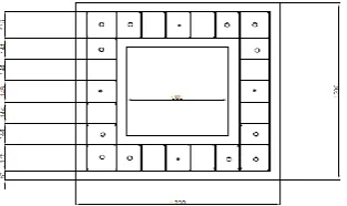
Figure 4: Reinforcement details of square column
Figure 5: Reinforcement details of circular column
7. RESULTS AND DISCUSSION
Figure 6: Total deformation of the square column
[image:3.595.310.482.324.485.2] [image:3.595.311.536.553.674.2]© 2019, IRJET | Impact Factor value: 7.211 | ISO 9001:2008 Certified Journal | Page 3730
Figure 7: Equivalent stress of the column
The equivalent stress exhibited by the column due to the loading shows the failure at the range of 0.04525 N/mm2.
Figure 8: Shear in the column
The shear resistance of the column lies between the minimum and maximum value of -5.877x10⁻⁸ to
4.8186x10⁻⁸ respectively .Thus the shear resistance of the
[image:4.595.311.537.410.529.2]structure is improved by shape memory alloy bars and energy dissipation bars
Figure 9: Total Failure in the column due to 5000kN
The total failure of the structure occurs while crossing the load bearing capacity of the structure beyond the 5000kN
, due to the overloading the top structure of the column fails and leads to the buckling of the structure.
7.1 CIRCULAR COLUMN
The circular column being loaded with the load of 5000kN and the column is deflected to the range of 7.9939x10
-5mm
Figure 10:Total deformation in the circular column
The equivalent stress exhibited by the circular column can bear the compression of the range of 0.00050612N/mm2.
Figure 11: Equivalent stress in the column
The column due to loading in horizontal direction causes the column to resist the shear upto 5.9112x10⁻⁹ N/mm2
as the column resists the maximum loading in horizontal direction .
© 2019, IRJET | Impact Factor value: 7.211 | ISO 9001:2008 Certified Journal | Page 3731
Figure 13 :Graph of load acting in the column
Figure 14: Graph interpreting total deformation of columns
Figure 15: Graph represents the stress of two columns
[image:5.595.47.260.104.233.2]
Figure 16: Graph interprets the shear resistance of the structure
The graph of load acting on the column describes as the load increases the stability of the structure fails to resist the force acting on it and the value of resistance in graph gradually decreases on maximum load acting on the vertical and horizontal direction
8.CONCLUSION
The axial behavior ,flexural ,total deformation , stress and shear of the segmental column has been analyzed for the structure The graph of loading as per the conditions are plotted .It exhibits good strength and shear resistance due to the presence of shape memory alloy bars and energy dissipation bars .The resistance capacity of hybrid reinforcement is much efficient than longitudinal reinforcement .
The joints with epoxy coating resists the maximum shear and upliftment of the structure , the resistance can be improved by using FRP jacketing which reduces the failure in joints and corrosion .The analysis of precast post tensioned segmental bridge column using Ansys software provides varying result along with easy data interpretation for analyzing .
9.SCOPE FOR FUTURE WORK
The analysis of post tensioned segmental bridge column will play a major role in accelerating bridge construction in short period of time by
Changing parameters of the columns
By providing best bond between the segmental joints.
By using shape memory alloy bar as a reinforcement bars .
Better energy dissipation bars along with higher resistance post tensioned bars with bonded condition .
[image:5.595.35.265.282.435.2]© 2019, IRJET | Impact Factor value: 7.211 | ISO 9001:2008 Certified Journal | Page 3732
REFERENCE
[1] M. Mashal, S.White& A. Palermo (2012) “ Concepts and Developments for Accelerated Bridge Construction and Dissipative Controlled Rocking”.
[2] H. Park and T. Eom (August 1-6,2004) “Energy dissipation capacity of flexure dominated reinforced concrete member ” .
[3] Jun-ichiHoshikuma, Shigeki Unjoh, Junichi Sakai (2005) “Seismic performnace and structural details of precast segmental concrete bridge columns”.
[4] Yu-Chen Ou , (June 2007) “Precast segmental post-tensioned concrete bridge columns for seismic regions”
[5] Sami Megally, Marc J. Veletzos, Kelly Burnell (2009)“Seismic performance of precast concrete segmental bridges : Summary of experimental research on segment to-segmentjoints”
[6] Sarah Billington, Robert Barnes and John Breen (September 1998) “A precast substructure design for standard bridgesystems”.
[7] Jun-ichiHoshikuma, Shigeki Unjoh, Junichi Sakai (2005) “Seismic performnace and structural details of precast segmental concrete bridge columns”.