warwick.ac.uk/lib-publications
Original citation:
Luo, Hua, Zhang, Yue, Li, Wei, Huang, Li-Ke, Cosmas, John, Li, Dayou, Maple, Carsten and
Zhang, Xun. (2017) Low latency parallel turbo decoding implementation for future terrestrial
broadcasting systems. IEEE Transactions on Broadcasting. pp. 1-9.
Permanent WRAP URL:
http://wrap.warwick.ac.uk/94345
Copyright and reuse:
The Warwick Research Archive Portal (WRAP) makes this work by researchers of the
University of Warwick available open access under the following conditions. Copyright ©
and all moral rights to the version of the paper presented here belong to the individual
author(s) and/or other copyright owners. To the extent reasonable and practicable the
material made available in WRAP has been checked for eligibility before being made
available.
Copies of full items can be used for personal research or study, educational, or not-for profit
purposes without prior permission or charge. Provided that the authors, title and full
bibliographic details are credited, a hyperlink and/or URL is given for the original metadata
page and the content is not changed in any way.
Publisher’s statement:
“© 20167 IEEE. Personal use of this material is permitted. Permission from IEEE must be
obtained for all other uses, in any current or future media, including reprinting
/republishing this material for advertising or promotional purposes, creating new collective
works, for resale or redistribution to servers or lists, or reuse of any copyrighted component
of this work in other works.”
A note on versions:
The version presented here may differ from the published version or, version of record, if
you wish to cite this item you are advised to consult the publisher’s version. Please see the
‘permanent WRAP URL’ above for details on accessing the published version and note that
access may require a subscription.
Low Latency Parallel Turbo Decoding
Implementation for Future Terrestrial
Broadcasting Systems
Hua Luo, Yue Zhang, Wei Li, Li-Ke Huang, John Cosmas, Senior Member, IEEE, Dayou Li,
Carsten Maple, and Xun Zhang
Abstract—As a class of high-performance forward error
correction codes, turbo codes, which can approach the chan-nel capacity, could become a candidate of the coding methods in future terrestrial broadcasting (TB) systems. Among all the demands of future TB system, high throughput and low latency are two basic requirements that need to be met. Parallel turbo decoding is a very effective method to reduce the latency and improve the throughput in the decoding stage. In this paper, a parallel turbo decoder is designed and implemented in field-programmable gate array (FPGA). A reverse address generator is proposed to reduce the complexity of interleaver and also the iteration time. A practical method of modulo operation is realized in FPGA which can save computing resources com-pared with using division operation. The latency of parallel turbo decoder after implementation can be as low as 23.2 us at a clock rate of 250 MHz and the throughput can reach up to 6.92 Gbps.
Index Terms—FPGA, interleave, low latency, parallel turbo
decoding, terrestrial broadcasting.
I. INTRODUCTION
T
ERRESTRIAL broadcasting technologies are facing a challenge that data rate demand from the users is increasing dramatically. The latest television standards such as HDTV (High Definition TV) and UHDTV (Ultra-High Definition TV) [1]–[3] require that the broadcasting system should support higher throughput and lower latency. Besides, future digital terrestrial TV broadcasting systems are expected to not only support traditional rooftop receivers but also mobile receivers. This makes the demand of mobile data traffic more urgent and drives the research of new digital terrestrial TV technologies [4]. Nowadays, people are not just satisfied with watching TV at home only, they also expect to enjoy broad-casting services with their mobile devices. Therefore the future broadcasting system has to support other services such as WiFiManuscript received February 3, 2017; revised March 31, 2017; accepted April 11, 2017. (Corresponding author: Hua Luo.)
H. Luo, Y. Zhang, and D. Li are with the University of Bedfordshire, Luton LU1 3JU, U.K. (e-mail:[email protected]).
W. Li and L.-K. Huang are with Cobham Wireless, Stevenage SG1 2AN, U.K.
J. Cosmas is with Brunel University, Uxbridge UB8 3PH, U.K. C. Maple is with the University of Warwick, Coventry CV4 7AL, U.K. X. Zhang is with Institute Supérieur d’Electronique de Paris, 75006 Paris, France.
Color versions of one or more of the figures in this paper are available online athttp://ieeexplore.ieee.org.
Digital Object Identifier 10.1109/TBC.2017.2704425
and Cellular Networks [5]. It is also a trend that the mobile broadband and broadcast services, indoor and outdoor services can converge together in the future [6].
As a high performance forward error correction code, turbo codes [7]–[12] are believed to be one of the most robust channel coding methods for wireless communica-tions. In particular, turbo codes are able to facilitate near-capacity transmission throughputs, leading to a wide deploy-ment in the state-of-the-art communication standards such as WiMAX [13] and LTE [14] and could be employed in future potential broadcasting standard [15]. The Logarithmic Bahl-Cocke-Jelinek-Raviv (Log-BCJR) algorithm is employed for the iterative decoding of turbo codes. The decoding process is time-consuming because of the serial nature of Log-BCJR algorithm, which is caused by data dependencies of its forward and backward recursions [17]. This makes it hard to meet the demand of system throughput and latency. More specifically, the target transmission throughput should be multi-Gbps and ultra-low end-to-end latencies can be expected to be targets for future wireless communication standards [16]. Therefore, parallelization of traditional turbo decoding is a practical and effective way to improve the throughput and reduce the system latency at the decoding stage.
Note that a number of parallel turbo decoders have been proposed previously, and most of them mainly tried to improve the level of parallelism in order to get a higher through-put and lower latency. In [18], a fully-parallel turbo decoder was implemented using analog decoder, but only short mes-sage lengths are supported. According to [19], a parallel turbo decoder algorithm that operates on the basis of stochastic bit sequences was proposed which requires more processing time than Log-BCJR algorithm. A high performance parallel turbo decoder was introduced in [20] with configurable interleaving network which is implemented on very-large-scale integra-tion (VLSI). A fully-parallel turbo decoding algorithm was studied in [21] which can support all LTE and WiMAX stan-dards. However, the computing complexity is too high and is not practical for hardware platform like FPGA.
For the sake of concept proving for future generation terrestrial systems, it is important that the parallel turbo decoding can be implemented on platform like FPGA due to the high cost of VLSI or Application Specific Integrated Circuits (ASIC). Besides, FPGA is believed to be a keystone for the Centralized/Cloud Radio Access Network (C-RAN),
2 IEEE TRANSACTIONS ON BROADCASTING
which is one of the promising evolution paths for future mobile network architecture [27]. In this paper, a parallel turbo decoder is implemented on a Testbed which is designed to support multi-Gbps throughput and deployed with several FPGA processors. A reasonable level of parallelism is cho-sen in order to meet the demand of throughput, latency and acceptable computing complexity as well. A reverse address generator is proposed in order to reduce the interleaver com-plexity and reduce the iteration time at the same time. Modulo operation is an essential part of interleave index generation. We designed a practical method of modulo operation which helps to reduce the complexity in FPGA especially when the parallelism level is high. The contribution of this paper is that we provided a feasible solution of parallel turbo decoder implementation on FPGA with latency reduced and throughput improved.
The rest of the paper is organized as follows. Section II provides the background knowledge of turbo encoding and traditional serial turbo decoding algorithm. In Section III, the parallel turbo decoder is introduced plus the proposed reverse interleaving address generator. The implementation of the decoder on FPGA is described in Section IV, in which the simplified modulo operation is introduced. Finally, the exper-imental results and latency/throughput comparisons are given in Section V and conclusions are made in Section VI.
II. TURBOENCODER ANDDECODER
In this section, the background knowledge of turbo encoder and decoder is introduced.
A. Turbo Encoder
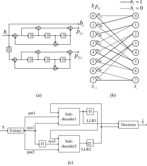
A turbo encoder is made up of two tail-biting recursive sys-tematic convolutional (RSC) encoders in parallel, as shown in Fig. 1(a). The second RSC encoder is placed after an inter-leaver (). These two encoders generate two N-bit encoded frames, named a parity frame and a systematic frame. Each RSC coding rate is R=1/2 with a codeword length of N and a constraint length of l =4. The encoder can also be repre-sented by a trellis diagram as shown in Fig.1(b) below. Since the message frame uses three encoded frames, the systematic frame (bi), the two parity frames (p1,i and p2,i), the turbo
encoder produces a total length of 3N bits frame xi and the
overall coding rate is R=1/3. Following turbo encoder, the encoded frames are modulated and transmitted to the receiver. The RSC encoder operates on the basis of an M =8-state transition diagram as shown in Fig.1(b). The encoder begins from an initial state of S0=0 and transits into each subsequent
state Si∈ {0,1,2, . . . ,M−1}according to the corresponding
message bit bi∈ {0,1}. Since the message bit bi ∈ {0,1}has
two possibilities, there will be 2 potential transitions from the previous state Si−1 to the current state Si.
B. Turbo Decoder
At the receiver side, the received frame yi can be extracted
[image:3.612.314.562.57.337.2]into 3 encoded frames: systematic frame (sys1), parity frame 1 (par1) and parity frame 2 (par2), according to the encoder. Turbo decoder includes two sub-decoders to perform iterative
Fig. 1. (a) Turbo encoder; (b) trellis diagram; (c) turbo decoder.
decoding. The sys1 and par1 are transmitted into sub-decoder 1 while sys2, which is generated from sys1 by inter-leave, and par2 is input into sub-decoder 2. The structure of the decoder is shown in Fig.1(c). Firstly, sub-decoder 1 generates extrinsic information LLR1 according to systematic, parity and a priori bits. LLR1 is utilized as a priori information by sub-decoder 2 after interleaving. Secondly, the new extrinsic information LLR2 generated by sub-decoder 2 is fed back to decoder 1 after the process of deinterleaver (−1). Therefore, the decoding iteration begins and after sufficient iterations, the performance of the decoder can approach to optimal.
An algorithm named BCJR was proposed in [22] for decoding convolutional codes and was updated by Yoon and Bar-Ness [23] to process tail-biting codes. For the encoded sequence x = x1,x2,x3, . . . ,xN, xi = [xi1,xi2,xi3]
is the code word for each input bit bi and xi1,xi2,xi3 are the
sys1, par1 and par2 respectively. As the message bit bi has
two possible values: 0 or 1, we can define the log-likelihood ratio (LLR) as
L(bi)=ln
P(bi=1)
P(bi=0)
(1)
The received sequence y=y1,y2, . . . ,yN is delivered to the
decoder for the estimation of the original bit bi. The decoding
algorithm computes a posteriori LLR given by
L(bi|y)=lnP(bi=1|y) P(bi=0|y)
(2)
if L(bi|y) > 0. Therefore, the key problem of decoding is the calculation of LLR. After LLR calculation, the extrinsic information will be obtained.
According to [28], the LLR can be defined by the joint probabilities of three parameters, the forward variable α, the backward variable β, and the transition probability γ. αand β can be computed by forward and backward recursions, which means that, to compute the LLR, at least 4N times of sampling periods are needed including interleaving and dein-terleaving. Let I be the iteration times of the decoding, the overall decoding latency can be given as:
D=4N·I. (3) This is the bottleneck of decoding in terms of latency. Therefore, parallel decoding is needed to reduce the decoding latency.
III. PARALLELTURBODECODING
In this section, the principle of parallel turbo decoding is introduced. The structure of parallel interleaver, which is one of the most complex part of parallel decoding, is explained as well. Moreover, a reverse address generator is proposed for parallel interleaving, which can reduce the time of the decoding process.
A. Parallel Decoding
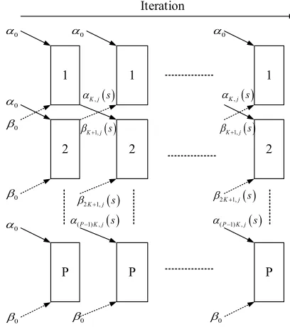
A parallel decoder is performing in parallel by separating the whole block into P sub-blocks, where P is the level of parallelism. In this way, the decoding time is reduced because the length of sub-block K =N/P is much smaller than the whole block. Generally speaking, the higher the level of par-allelism, the less decoding time is needed. According to the parallel decoding algorithm proposed in [23], as shown in Fig. 2, the last forward variable α(p−1)K,j(s) and backward
variableβpK+1,j(s)from the previous iteration of the neighbor
sub-blocks ((p−1)th and (p+1)th) are utilized as the ini-tial value of computation for this pth sub-block. Here, αi,j(s)
andβi,j(s)represent the forward and backward information at
jth trellis stage of the ith decoding bit with state s. α0 and
β0denote the forward and backward initial variable values of
each sub-block in the first iteration and also represents the first and last sub-blocks in the later iterations respectively.
Note that between each iteration, the output LLR of the previous iteration will be processed by interleaving/deinterleaving. For simplicity, the interleav-ing/deinterleaving process is not shown in Fig. 2. All the decoders of each sub-block are performed in parallel and simultaneously so that the parallel decoder can reduce the decoding time to 1/P of the sequential decoding time.
B. Interleave and Deinterleaving
[image:4.612.332.536.53.283.2]The interleaver is a very important part of channel coding performance of turbo codes. For the cooperation of paral-lel decoding iteration, the interleaver/deinterleaver should be designed to be parallel as well. A memory access contention may occur during the interleaving of extrinsic information. Therefore, based on some algebraic constructions, contention-free interleavers have been proposed in [24] and [25] and
Fig. 2. Parallel forward and backward computation.
references therein. In our case, the block size is N, the interleaver is defined as
(i)=A(i)mod N
A(i)=f1i+f2i2 ,i=0,1,2. . . ,N−1, (4)
where f1is an odd number and f2is even, i is the index number
of input data yiand(i)is the index number after interleaving.
For the parallel interleaver, if the parallel level P can divide block size N, then this interleaver is contention-free [20].
In order to generate the target interleaving address according to (4), the compute complexity is quite high if using real-time multiply operation to calculate A(i) because the index i increases progressively till N−1. Therefore, an optimized address generator is proposed in [20], which has low com-plexity. The address generation is accomplished by recursion and the derivation is as follows. According to (4),
A(0)=0,A(1)=f1+f2
A(i+1)−A(i)=f1+f2+2i·f2
A(i+2)−A(i+1)=f1+3f2+2i·f2 (5)
then
A(i+2)−2A(i+1)+A(i)=2f2. (6)
Since A(0) and A(1)are known initial factors, by recursion, the following interleaving index can be generated from (6). In this way, no multiplication is needed, which helps reduce com-plexity dramatically. This address generator cannot be used in a parallel interleaver directly because all the sub-blocks are processing simultaneously hence a parallel address generator is needed.
The memory of parallel interleaver is divided into P banks corresponding to Psub-blocks. The ith extrinsic informa-tion will be stored in the (i)/Kth bank at the address of
4 IEEE TRANSACTIONS ON BROADCASTING
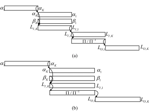
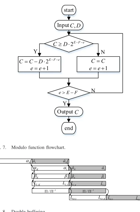
Fig. 3. Timing diagram of each iteration; (a) original sequence interleaving; (b) reversed sequence interleaving.
C. Reverse Address Generator
Based on the forward and backward computation structure of turbo codes, the sequence of backward variables βi,j(s)
should be reversed in order to calculate the extrinsic infor-mation. This process adds processing time by at least N clock cycles for sequential decoding or K clock cycles for parallel decoding as shown in Fig.3(a). Utilizing the characteristics of interleaving, the sequence of extrinsic information can remain reversed and does not affect interleaving while the processing time can be reduced to 3/4 of the original sequence interleav-ing (see Fig. 3(b)). LI,k,k = 1,2, . . . ,K and LO,k represent
the LLR of a sub-block before interleaving/deinterleaving and after interleaving/deinterleaving respectively.
Since the sequence of interleaver input is reversed, the address generator should be changed accordingly. Therefore, we proposed a reversed address generator for parallel turbo decoding to reduce the computation complexity and processing latency as well.
The address of target memory bank (i)mod K can be modified as
⎧ ⎪ ⎪ ⎨ ⎪ ⎪ ⎩
p,k =(pk)mod K
=A(pk)mod K,k=K−1,K−2, . . . ,0, p=1,2, . . . ,P
A(pk)=f1pk+f2(pk)2.
(7)
Note that the first two addresses of each sub-block that need to be generated arep,K−1andp,K−2. According to (7),
p,K−1=f1p(K−1)+f2(p(K−1))2 mod K
p,K−2=f1p(K−2)+f2(p(K−2))2 mod K, (8)
since f1, f2and p are all integers, (8) can be simply modified to
p,K−1= −f1+2f2mod K
p,K−2= −2f1+4f2 mod K. (9)
Using similar derivation as (5), the following address of each filter bank can be generated by recursion
p,k+2−2p,k+1+p,k=2f2 mod K. (10)
From (10), we can find that the recursion process and initial values have nothing to do with p hence the addresses of all these sub-blocks are the same and only one channel of address generator is necessary for this parallel interleaver.
k+2−2k+1+k=2f2mod K (11)
The destination bank that the LLR of a sub-block should be mapped into is decided by the value of(i)/K. The divi-sion operation here is costly therefore recursive computation is needed for this reverse address generator. Let (i)/K be redefined as
p,k =(pk)/K
=[A(pk)mod N]/K (12)
The recursion has two dimensions. First, the recursion direc-tion is from k=K−1 to k=0.p,K−1 andp,K−2 are the
initial values. Second, another recursion is performed from p = 1 to p = P where 1,k and 2,k are the initial
val-ues. In order to accomplish this two dimensional recursion, 1,K−1, 1,K−2, 2,K−1 and 2,K−2 must be known before
the computation.
p,k+2−2p,k+1+p,k=[2p2f2mod N]/K
p+2,k−2p+1,k+p,k=[2K2f2 mod N]/K (13)
Since the interleaver/deinterleaver is placed after the whole computation of αi,j(s), 1,K−1, 1,K−2, 2,K−1 and 2,K−2
can be calculated via pipeline of the multiplication cell before the address generator, as well as [2p2f2mod N]/K
and [2K2f2mod N]/K. By this recursion, no realtime
multi-plication is needed during the address generation. With the reverse address generator mentioned above, the parallel inter-leaver/deinterleaver can reduce processing time compared to the method in [20] even though it may cost a little more computation resources.
IV. TURBODECODERIMPLEMENTATION
Due to its low cost and short development cycle, FPGA is one of best hardware platform choices for a real-time proof of concept system. In this work, the parallel LTE turbo decoder including the proposed interleaving address generator is imple-mented on Xilinx Virtex VII. In this section, the detail of decoding implementation is introduced. This decoder can sup-port all the block sizes of the LTE standard. Different parallel level P can be configured according to the specific block size. Considering that the higher the parallel level is, the more com-plex the decoder will be and the more computing resources will be used, P is set to be 64 when the block size N ranges from 2048 to 6144 and P = 8 when 256 ≤ N < 2048, otherwise P=1.
A. Extraction
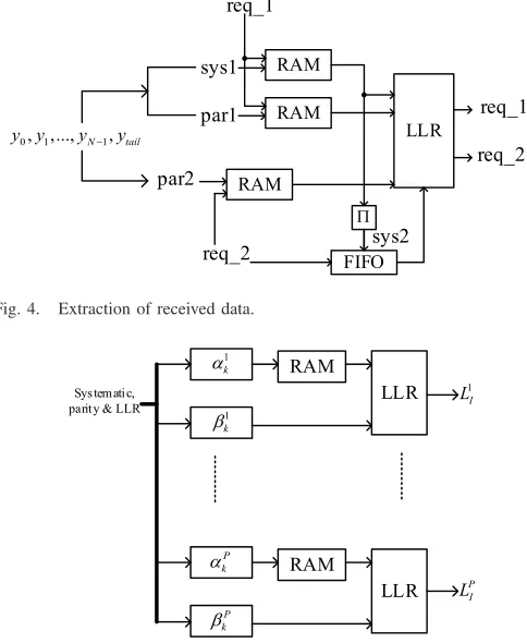
Fig. 4. Extraction of received data.
Fig. 5. Parallel extrinsic information calculation.
par2 for sub-decoder 2, as shown in Fig.4. A FIFO is placed after interleaver in order to synchronize with par2.
Since during the iteration of decoding, all these systematic and parity frames that are going to be reused, sys1, par1 and par2, are stored in block RAMs and the read of RAMs is con-trolled by the request signals (req_1 and req_2) from the LLR calculation module. As the extraction will generate a group of parallel input data for LLR calculation, a configurable parame-ter is used here to make this decoder compatible with different parallelism levels. Moreover, to produce the same number of block RAMs according to the parallel level, the method of source code generation is utilized. For example, this generate operation was created in Verilog HDL.
B. Extrinsic Information
Extrinsic information calculation includes forward variable α and backward variable β calculation. As shown in Fig. 5, a block RAM is placed afterαmodule in order to reverse the sequence as mentioned in Section III. Source code generation is used here as well to produce P groups of α modules, β modules and LLR modules.
Note that in the theoretical calculation ofα andβ,
αi,j(s)= −∞,s=1
βi,j(s)= −∞,s=1. (14)
However, minus infinity does not exist in practical fixed-point calculation. A logical comparitor is utilized because if α =
[image:6.612.327.540.58.166.2]−∞, then α+x = −∞ where x can be any value except infinity. Hence −∞ in FPGA is replaced by a least signed
Fig. 6. Parallel Interleaving.
value. More specifically, in our case, a 16 bit hexadecimal 2’s complement value 8000H is used. By comparison, ifαequals 8000H, then α+x is still 8000H. The same method is used to deal withβ.
C. Interleaver/Deinterleaver
As mentioned in Section III, the interleaver is contention-free as long as the parallel level P can divide the block size N. Memory contention does not happen in our study because all the block sizes can be divided by P. The inter-leaver/deinterleaver is a memory dynamic mapping process. The target address and memory bank are generated by the proposed reverse address generator. As shown in Fig. 6, for the interleaving process, using multiplexer in FPGA, the real-time LLR can be written into the related block RAMs and read from them sequentially after writing has been completed. As mentioned in Section III, the RAM write addressp,kof
each sub-block is independent of p so only 1,k is produced
from the address generator. The LLR results of LLR modules are mapped to different RAMs according top,k. On the other
hand, the write process is sequential for deinterleaver while read address(i)and bank number(i)are generated by the address generator.
D. Modulo Operation
Modulo operation C%D is a costly part of the address gen-erator. The result of modulo is the remainder of a division operation. For Xilinx FPGA, the only existing function for modulo operation is the division intellectual property (IP) core which takes many logic units. Some other faster methods like the bitwise operation also exist but they assume D as a con-stant or the number of powers of 2 [26]. In our study, D is not a constant or a power of 2. A modulo function based on Verilog HDL should be designed with less computing resource and fast speed as well.
Inspired by the bitwise operation, we designed a modulo function that uses a shifter and comparator to get the remainder of the division but not the quotient. Let E be the maximum bit width of C, F be the maximum bit width of D. The procedure of the proposed modulo function is as Fig.7 below.
E. Double Buffering
6 IEEE TRANSACTIONS ON BROADCASTING
[image:7.612.60.291.48.397.2]Fig. 7. Modulo function flowchart.
Fig. 8. Double buffering.
is idle when the latter module is working. For instance, as shown in Fig. 3,β module works after the whole sub-block calculation of α. Obviously, another sub-block ofαcan keep calculating during that period, as shown in Fig. 8 below. In this way, the whole decoder can decode two frames simul-taneously which can nearly double the throughput. Double buffering is very functional as only double storage space is used, however the logic and compute resources, e.g., lookup tables (LUTs), Flip-Flop, Multipliers, are reused so the utilization of FPGA resource is more efficient.
Based on the proposed reverse address generator and the double buffering technique, the parallel decoding latency after implementation can be give as:
D=(3N+12)/4+(3N/P)·(I+1)+ t, (15) where t is the latency brought by the FPGA modules such as RAMs, multipliers, FIFOs, modulo operation, and so forth. The value of t depends on how the decoder is implemented.
V. EXPERIMENTRESULTS
In this Section, the Testbed system and the results of parallel turbo decoder implementation are introduced. In order to meet the requirements of future broadcasting system, this Testbed is designed to support multi-Gbps decoding throughput. The structure of it can be found in Fig.9.
[image:7.612.341.539.55.146.2]The X86 Server is the control center of this Testbed, which is connected via Peripheral Component Interconnect
Fig. 9. Testbed system structure. TABLE I
THROUGHPUT ANDLATENCYCOMPARISON
Express (PCIe) with BEE7. BEE7 is a programmable hardware platform used for algorithm exploration, research, prototyping and so on. Four Xilinx Virtex-7 FPGAs are allocated on this platform. With one FPGA processor, the throughput require-ment cannot be met. BEE7 is linked with several RF frontends to build a MIMO transceiver.
As we know that higher parallelism means lower latency, it also takes more computing resources especially logic resources such as LUTs and Flip-Flops. For one FPGA in BEE7, the par-allel level can reach to P =64 with a latency of 23.2 us at 250 MHz clock rate where the iteration times is 8. Although the latency is quite low compared to lower parallelism, the throughput of this system is only 2.12 Gbps which is not enough. The throughput and latency comparison of different parallel levels are listed in Table I.
The results above are obtained via ModelSim simulation after placement and routing. This simulation can measure how many clock cycles are needed for a whole decoding process. By some simple calculation, the latency and throughput can be calculated. It can be seen that when the parallel level is 8, which is 8 times lower than 64, then the latency is not 8 times larger. This is because the extraction of the received data takes a fixed amount of time. Moreover, since it takes much fewer resources when P=8, 8 parallel turbo decoders can be put on a single FPGA at the same time, which makes the throughput reach to 6.92Gbps. Even though the throughput is low when P=64 because only one decoder can be put on the FPGA, its good latency performance can still be used for the case of a strict latency requirement.
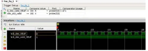
Fig. 10. Decoding results capture. TABLE II
MODULOOPERATIONCOMPARISON
a block RAM. By capturing the output of the turbo decoder, the decoding results can be examined. As shown in Fig. 10, the original frame before turbo encoding is a square wave, and we can see that the output is a square wave that matches the original frame.
For LTE standard, the maximum number of C is A(6143) in (4), the bit width E cannot be larger than 35 and F cannot be greater than 13. Therefore, it only takes 22 clock cycles to finish modulo operation. The latency and complexity compar-ison between this function and the division IP can be found in Table II.
TableII shows that modulo function we designed can save nearly 3/4 slice registers compared to the IP from Xilinx although it takes a little more slice LUTs. It is significant that modulo function can save much more slice registers when the parallel level is high, e.g., P=64, and it uses less clock cycles to complete the computation.
[image:8.612.52.293.193.316.2]For LTE standard, block error rate (BLER) is used to test the decoder performance. The BLER of this decoder is eval-uated via MATLAB simulation and ModelSim simulation. MATLAB simulation results are used as the reference of decoding BLER. The encoded frames with Gaussian white noise are first written into a test file and then read by Verilog test file. By Monte Carlo simulation, 1000 random frames for each signal-to-noise ratio (SNR) value, the BLER of different SNR can be obtained as shown in Fig. 11. Since the simu-lation is performed without rate mapping and modusimu-lation, it works well even at very low SNR. The purpose of this sim-ulation is to make sure that the decoder implementation is working as expected. We can see that the BLER results of our FPGA parallel decoder are similar to its MATLAB theoret-ical simulation. The BLER is slightly higher because of the fixed point quantification error. Moreover, although the paral-lel decoder can increase system throughput and reduce latency, the BLER performance will be degraded.
Fig. 11. BLER simulation results.
There exist better ways to test the decoder, such as trans-fer the decoding results back to the server. By comparing the original bits and the decoded bits at the server side, the real-time block error rate (BLER) can be obtained. However, this part is not available at this moment and will be a part of our further research in the near future.
VI. CONCLUSION
Parallel turbo decoding is a practical way to increase the system throughput and reduce the latency in order to meet the requirements of future terrestrial broadcasting systems. In this paper, the implementation on FPGA of the parallel turbo decoder is introduced. A reverse address generator of inter-leaver/deinterleaver is proposed to reduce the processing time of each iteration and decrease latency further. The address gen-erator uses recursion to generate the realtime address needed by the interleaver, which saves computing resources. A mod-ulo function, that uses fewer clock cycles and logic resources compared to the Xilinx division IP, is designed to perform modulo operation. Moreover, in order to utilize the limited FPGA resources more efficiently, a double buffering technique is used to double the throughput in this parallel turbo decoder, which needs more storage space but reuses the logic resources. The implementation of this decoder is accomplished on a Testbed system with 4 FPGA processors. On the one hand, by capturing the decoding results via Xilinx ILA, the valid-ity of the parallel decoder is evaluated. On the other hand, the latency and BLER is tested by ModelSim simulation after placement and routing. The system decoding through-put is calculated based on the latency measured. Although the throughput of this Testbed is less than 10Gbps, which is the demanded requirement of next generation wireless com-munication systems, our research gives a clue that parallel turbo decoder can be implemented on FPGA and meet multi-Gbps throughput requirement at the same time and that the throughput can be further improved by using more hardware resources.
REFERENCES
8 IEEE TRANSACTIONS ON BROADCASTING
[2] T. Biatek, W. Hamidouche, J.-F. Travers, and O. Deforges, “Optimal bitrate allocation in the scalable HEVC extension for the deployment of UHD services,” IEEE Trans. Broadcast., vol. 62, no. 4, pp. 826–841, Dec. 2016.
[3] S. Saito et al., “8K terrestrial transmission field tests using dual-polarized MIMO and higher-order modulation OFDM,” IEEE Trans.
Broadcast., vol. 62, no. 1, pp. 306–315, Mar. 2016.
[4] D. Vargas, Y. J. D. Kim, J. Bajcsy, D. Gómez-Barquero, and N. Cardona, “A MIMO-channel-precoding scheme for next generation terrestrial broadcast TV systems,” IEEE Trans. Broadcast., vol. 61, no. 3, pp. 445–456, Sep. 2015.
[5] J. Calabuig, J. F. Monserrat, and D. Gómez-Barquero, “5th generation mobile networks: A new opportunity for the convergence of mobile broadband and broadcast services,” IEEE Commun. Mag., vol. 53, no. 2, pp. 198–205, Feb. 2015.
[6] L. Dai, Z. Wang, and Z. Yang, “Next-generation digital television terres-trial broadcasting systems: Key technologies and research trends,” IEEE
Commun. Mag., vol. 50, no. 6, pp. 150–158, Jun. 2012.
[7] J. P. Woodard and L. Hanzo, “Comparative study of turbo decoding techniques: An overview,” IEEE Trans. Veh. Technol., vol. 49, no. 6, pp. 2208–2233, Nov. 2000.
[8] Y. G. Debessu, H.-C. Wu, H. Jiang, and S. Mukhopadhyay, “New modified turbo decoder for embedded local content in single-frequency networks,” IEEE Trans. Broadcast., vol. 59, no. 1, pp. 129–135, Mar. 2013.
[9] I. A. Chatzigeorgiou, M. R. D. Rodrigues, I. J. Wassell, and R. A. Carrasco, “Comparison of convolutional and turbo coding for broadband FWA systems,” IEEE Trans. Broadcast., vol. 53, no. 2, pp. 494–503, Jun. 2007.
[10] M. F. Brejza et al., “20 years of turbo coding and energy-aware design guidelines for energy-constrained wireless applications,” IEEE Commun.
Surveys Tuts., vol. 18, no. 1, pp. 8–28, 1st Quart., 2015.
[11] Z. He, P. Fortier, and S. Roy, “Highly-parallel decoding architectures for convolutional turbo codes,” IEEE Trans. Very Large Scale Integr. (VLSI)
Syst., vol. 14, no. 10, pp. 1147–1151, Oct. 2006.
[12] O. Muller, A. Baghdadi, and M. Jezequel, “From parallelism levels to a multi-ASIP architecture for turbo decoding,” IEEE Trans. Very Large
Scale Integr. (VLSI) Syst., vol. 17, no. 1, pp. 92–102, Jan. 2009.
[13] IEEE Standard for Air Interface for Broadband Wireless Access Systems, IEEE Standard 802.16-2012, pp. 1–2542, Aug. 17, 2012.
[14] LTE; Evolved Universal Terrestrial Radio Access (E-UTRA); Multiplexing and Channel Coding, ETSI, Sophia Antipolis, France,
Feb. 2013.
[15] L. Christodoulou, O. Abdul-Hameed, A. M. Kondoz, and J. Calic, “Adaptive subframe allocation for next generation multimedia delivery over hybrid LTE unicast broadcast,” IEEE Trans. Broadcast., vol. 62, no. 3, pp. 540–551, Sep. 2016.
[16] “5G radio access,” Ericsson White Paper, Stockholm, Sweden, Tech. Rep. 284 23-3204 Uen, Jun. 2013.
[17] P. Robertson, E. Villebrun, and P. Hoeher, “A comparison of optimal and sub-optimal MAP decoding algorithms operating in the log domain,” in
Proc. IEEE Int. Conf. Commun., vol. 2. Seattle, WA, USA, Jun. 1995,
pp. 1009–1013.
[18] D. Vogrig et al., “A 0.35-μm CMOS analog turbo decoder for the 40-bit rate 1/3 UMTS channel code,” IEEE J. Solid-State Circuits, vol. 40, no. 3, pp. 753–762, Mar. 2005.
[19] Q. T. Dong, M. Arzel, C. J. Jego, and W. J. Gross, “Stochastic decod-ing of turbo codes,” IEEE Trans. Signal Process., vol. 58, no. 12, pp. 6421–6425, Dec. 2010.
[20] Z. Yan, G. He, W. He, S. Wang, and Z. Mao, “High performance parallel turbo decoder with configurable interleaving network for LTE application,” Integr. VLSI J., vol. 52, pp. 77–90, Jan. 2016.
[21] R. G. Maunder, “A fully-parallel turbo decoding algorithm,” IEEE Trans.
Commun., vol. 63, no. 8, pp. 2762–2775, Aug. 2015.
[22] L. Bahl, J. Cocke, F. Jelinek, and J. Raviv, “Optimal decoding of lin-ear codes for minimizing symbol error rate,” IEEE Trans. Inf. Theory, vol. 20, no. 2, pp. 284–287, Mar. 1974.
[23] S. Yoon and Y. Bar-Ness, “A parallel MAP algorithm for low latency turbo decoding,” IEEE Commun. Lett., vol. 6, no. 7, pp. 288–290, Jul. 2002.
[24] A. Tarable, G. Montorsi, and S. Benedetto, “Mapping of interleaving laws to parallel turbo decoder architectures,” in Proc. 3rd Int. Symp.
Turbo Codes Related Topics, Brest, France, Sep. 2003, pp. 153–156.
[25] O. Y. Takeshita, “On maximum contention-free interleavers and permu-tation polynomials over integer rings,” IEEE Trans. Inf. Theory, vol. 52, no. 3, pp. 1249–1253, Mar. 2006.
[26] J. T. Butler and T. Sasao, “Fast hardware computation of x mod z,” in
Proc. 18th Reconfigurable Architect. Workshop (RAW 2011), Anchorage,
AK, USA, May 2011, pp. 294–297.
[27] Altera. (Jun. 2016). Baseband-C-RAN. [Online]. Available:
https://www.altera.com/solutions/industry/wireless/applications/ baseband/c-ran.html
[28] H. R. Sadjadpour, “Maximum a posteriori decoding algorithms for turbo codes,” in Proc. SPIE Digit. Wireless Commun. II, vol. 4045, pp. 73–83, Jul. 2000.
Hua Luo received the B.E. and M.E. degrees from
the University of Electronic Science and Technology of China in 2011 and 2014, respectively. He is cur-rently pursuing the Ph.D. degree with the University of Bedfordshire, U.K. His research interests include hardware impairments calibration of massive MIMO systems, MIMO signal processing, MIMO-OFDM systems, and beamforming techniques.
Yue Zhang received the B.E. and M.E. degrees from the Beijing University of Post and Telecommunications, China, in 2001 and 2004, respectively, and the Ph.D. degree from Brunel University, U.K., in 2008, where was also a Research Engineer for the EU IST FP6 project-PLUTO. Since 2008, he has been a Signal Processing Design Engineer with the Microwave Measurement Division-Europe, Anritsu Corporation. He was responsible for the RF/IF, digital, and DSP design for the measurement instruments for various wireless and broadcasting systems. In 2010, he joined the Department of Computer Science and Technology, University of Bedfordshire, Luton, U.K., as a Reader in Signal Processing. He was a Royal Academy of Engineering, U.K., Industrial Secondment with Aeroflex Ltd. His research interests are signal processing, wireless and broadcasting systems, MIMO-OFDM systems, radio propagation model, and multimedia and wireless networks. He currently serves as an Associate Editor for the IEEE TRANSACTIONS ONBROADCASTING.
Wei Li received the Ph.D. degree from the University of Bedfordshire in 2015. He is currently an Algorithm Engineer with Cobham Wireless, U.K. His research interests are statistic and stochas-tic signal processing.
Li-Ke Huang received the B.Sc. degree in
John Cosmas (M’89–SM’08) was born in Colombo,
Sri Lanka, in 1956. He received the B.Eng. degree in electronic engineering from Liverpool University in 1978 and the Ph.D. degree from Imperial College, University of London in 1986. He is cur-rently a Professor of Multimedia Systems with the College of Engineering, Design and Physical Sciences, Brunel University London. He co-leads the Wireless Networks and Communications Research Centre, is the course director of M.Sc. Advanced Multimedia Design and 3-D Technologies. He is an Associate Editor of the IEEE TRANSACTIONS ONBROADCASTING. His research interests are concerned with the development of multimedia systems applied to future of broadcasting, cellular communications, 2-D/3-D digital video/graphics media and the synergies between these technologies towards their application towards the benefit of the environment, health and soci-eties. He has participated in eleven EU-IST and two EPSRC funded research projects since 1986 and he has led three of these (CISMUNDUS, PLUTO, and 3-D MURALE). His latest research is concerned with management of hetero-geneous cellular networks, convergence of cellular and ad-hoc networks, 3-D MIMO, and efficient software defined networks architectures.
Dayou Li received the B.Eng. and M.Sc. in
transportation automation from Beijing Jiaotong University, China, in 1982 and 1985, respectively, and the Ph.D. from Cardiff University in 1999. His research interests focus on uncertainty handling in human–robot interaction to enable seamless team-work involving human users and robots. His research has been published on IEEE TRANSACTIONSand various robotics research journals. He has led and participated in five European Union funded projects in recent years, including SRS project which aims to develop a semi-autonomous technique to allow robots to be manipulated remotely when facing unstructured environments and to pick up new skills through the manipulation processes. He also works on nano-robots that are able to manipulate cells to obtain their properties and to inject drugs directly into cells, which may lead to the early diagnosis and personalized treatment for many diseases. He is the member of IEEE Robotics and Automation Society.
Carsten Maple leads the GCHQ-EPSRC recognized
Academic Centre of Excellence in Cyber Security Research with the University of Warwick, where he is a Professor of Cyber Systems Engineering and the Director of Research in Cyber Security in WMG. He has published over 200 peer reviewed papers and his research has attracted millions of pounds in funding and has been widely reported through the media. He is the Chair of the Council of Professors and Heads of Computing in the U.K. and is the Privacy and Trust stream lead for PETRAS, the U.K. Research Hub for Cyber Security of the Internet of Things where he manages projects in Transport & Mobility and Control Systems and Supply Chain. He is currently funded by a range of sponsors including EPSRC, EU, DSTL, the South Korean Research Agency, Innovate U.K., and private companies.
Xun Zhang received the B.Eng. degree from