CLIPPER User's Guide
DSA030070
January
1990
SSSOO6',SSSOO62.SSS0075.SSA0075
DSA03001S (Spine). DSA03001T
(BleedTabs). DIXGDMRSl (Binder)
Warning
This equipment contains no user serviceable
partS.
Voltages and energy levels in this equipment may be harmful if acCeSsed. Contact. the In~rgraph field service if the unit requires service.A vertbBmlen.t
Aucune des pieces de cet equipem.ent ne peut etre entretenue par lutilisateur. Certains voltages et niveaux energetiques dans cetequipement peuvent etre d'un contact
dangereux. S'adresser au bureau d'entretien en clientele Intergraph si. la machine necessite un entretien.
Wamung
In diesem Gerat sind keine Teile enthalten, die vom Benutzer repariert werden konnen. 1m Inneren dieses Gerates treten Spannungen und Stromstarken auf, die gefahrlichsein konnten. Benachrichtigen Sie den Intergraph Aussendienst, wenn dieses Gerat Wartung benotigt.
Advertencia
En el interior de este equipo, no hay piezas que e1 usario puede reparar. Los niveles de tension y potencia que existen en este equipo pueden resultar peUgroso si se establece contacto. Si 1a unidad necesita
alguna
reparacion, comuniquese con la oficina deservicios de Intergraph. . .
Avvertenza
Frequency Interference
This equipment generates, uses, and can radiate radio frequency energy, and if not installed and used in accordance with the instruction manual may cause interference to radio communications. It has been tested and found to comply with the limits for a class A computing device pursuant to subpart J of part 15 of FCC rules, which are designed to provide reasonable protection against such interference when operated in a commercial environment.
The Power Cord for 27", 19" and 15" Monitors
The power cord normally provided with this unit is for use· only in the United States and Canada. This cord set is rated at 120 V AC, 60 Hz, 15 Amps and should only be used when this kind of power is available. The cord set should be visually checked to verify. if it is intended for use on North American units.
For units set to 120 V, a UL Listed Cord Set rated 15 A, 120 V is provided. The cord set should be visually checked to verify whether it is intended for use on North American units.
Caution:
If the cord set provided must be replaced, the replacement set must meet the following requirements:
• The cord must have a type with two conductors and a ground wire. Each conductor and ground must be multistranded with each conductor and the ground having a cross-sectional area no less than .75 mm square. The cord must not exceed 4.6 m in length. The cord set should have the appropriate safety
approvals for the country in which the equipment will be installed and marked HAR. The cord set must be rated for no less than 6 A, 240 V.
• The appliance inlet is an IEC-320/-C13 type connector. The power cord connector that mates to the appliance inlet connector must be an IEC-320/-C13 type connector.
• The cord and connectors must display the International Harmonization Mark <HAR> or the mark of the national safety testing laboratory for the country in which the unit is to be installed. The cord and connectors must be rated for no less than 240 V AC, SO Hz, 6 Amps.
Le
Cordon Electrique:
Le cordon electrique fourni normalementavec cet apparell ne doit etre utilise qu'aux Etats-Unis et au Canada. Sa tension nominale est de 120 volts en courant alternatif, 60 Hz, 15 amperes et II ne doit etre utilise que sous ces conditions. 11 faut verifier Ie cordon d'alimentation pour s'assurer qu'll est bien destine aux appareils nord-americains.
Attention:
Les caracteristiques du (',ordon d'alimentation, en cas de remplacement de celui-ci, doivent etre les suivantes:
• Le cordon doit etre du type a deux fils conducteurs et un fll de terre. Chaque fll, conducteur et de terre, doit etre a brins multiples et sa section doit etre d'0,75 mm carre au minimum. 11 ne faut pas que la longueur du cordon depasse 4,60 m. Le cordon et les connecteurs doivent etre marques du symbols de standardisation international <lIAR> ou estampilles par Ie Laboratoire National d'Essais du pays ou l'appareil va etre utilise. La tension nominale du cordon et des connecteurs doit etred'un minimum de 240 volts en courant alternatif, 50 Hz, 6 amperes.
• La prise de 1a platine de raccordement est un connecteur de type IEC-320/-C13.
Le connecteur du cordon electrique qui s'accouple au connecteur de Ia platine de raccordement doit egalementetre du type IEC-320/-C14.
• Ce moniteur n'est pas destine' a une connexion directe sur Ie reseau electrique.
Das Netzanschluss-Kabel fur 19" und 15" Bildschirme
Das mit dieser Einheit ublieherweise zur Verfugung gestellte Netzanschluss-Kabel ist nur fur den Gebraueh in den USA und in Kanada bestimmt. Dieser Netzanschluss
Kabelsatz hat die Nennwerte von 120 V AC, 60
Hi'
und 15 Ampere und darf nur verwendet werden, wenn diese Bedingungen gewahrleistet sind. Es muB genauuberpruft werden, ob er fur den Gebraueh an nordamerikanisehen Einheiten vorgesehen ist.
Wamung:
Beim Auswechseln des beigegebenen Kabelsatzes muB der Austauschsatz folgenden Bedingungen entsprechen:
• Des Kabel muB zwei Leitungsdrahte und einen Erdungsdraht haben. Die
Kabeladern mussen mehrfaeh verlitzt ~in, sodaB,die Quersehnittflaehe jeder Ader mindestens 0,75 qmm betragt. Die Lange des Kabels darf 4,6 m nieht
uberschreiten. DasKabel und die Stecker mussen das VDE-Zeichen fur diese Einheit aufweisen. Die Nennwerte fur Kabel und Stecker durfen nicht unter 240 V AC, 50 Hz und 6 Ampere liegen .
EI Cable de Coneccion:
El cable de coneccion que se provee con esta unidad es para uso exclusivo en los Estados Unidos y Canada. Este cable es apto para 120 VCA, 60 Hz, 15 Amp y solo debe usarse con este tipo de corriep.te electrica. Antes de usarse, deberia verificarse que este cable este aprobado para uso en Norteamerica.
Precaucion:
En caso de que se necesite sustituir este cable, el cable que 10 reemplace debe reunir las siguientes especificaciones:
• El cable debe tener dos conductores y una toma a tierra. Los conductores y la toma a tierra deben ~r de filamentos trenzados con un area transversal de no menos de 0,75 mm cuadrados. Su longitud no debe exceder los 4.6 m. El cable y los enchufes deben tener 1a marca International Harmonization <lIAR> 0 la marca del laboratorio nacional de controles de seguridad del pais donde se instale la unidad. El cable y los enchufes deben estar homologados para no menos de 240 VCA, 50 Hz y 6
Amp .
n
Cavo
di
Alimentazione
II cavo di alimentazione, che viene norma}.mente fornito con questa unita, e per uso esclusivo negli Stati Uniti e Canada. Questo iUsieme di cavi e dimensionato per 120 V AC (tensione altemata), 60 Hz, 15 Ainpere e dovrebbe essere usato soltanto quando questa tipo di energia e disponibile. L'insieme dei cavi dovrebbe essere controliato visualmente per verificare se sia per uso nelie unita statunitensi.
Attenzione:
Se l'insieme di cavi fornito deve essere sostituito, l'insieme di sostituzione deve essere conforme ai seguenti requisiti:
• 'll cavo deve essere di un tipo avente due conduttori e un filo di terra. Ciascun conduttore. e filo di terra deve essere intrecciato con piu fili a ciscun conduttore e filo di terra, avente una sezione incrociatanon inferiore a .0,75 mm quadrati. II cavo non deve eccedere 4,6 m di lunghezza. II cavo e i connettori devono mostrare il Marchio di Armonizzazione Internazionale CHAR) 0 il marchio del
laboratorio di controlio sicurezza nazionale per i1 paese nel quale l'unita deve essere installata. II cavo e i connettori devono essere regolati per non meno di 240 V AC, 50 Hz, 6 Ampere .
Warranties and Liabilities
All warranties given by Intergraph Corporation about equipment or software are set forth in your purchase contract.
The information and the software discussed in this docuIijent are subject to change without notice and should not be considered commitments by Intergraph Corporation. Intergraph Corporation assumes no responsibility for any errors that may appear in this document.
The software discussed in this document is furnished under a license and may be used or copied only
in accordance with the terms of this license.
No responsibility is assumed by Intergraph for the use or reliability of software on equipment that is
not supplied by Intergraph or its affiliated compal1.ies.
Trademarks
Intergraph is a registered tradenut.rk of Intergraph Corporation. Intergraph. InterPro, InterAct, InterServe, and InterView are registered trademarks of Intergraph Corporation. CLIPPER is a trademark of Intergraph Corporation.
Classifications
This equipment is designed to comply with the requirements in Part 15 of the FCC rules for a class A computing device.
Copyright
© 1990, INTERGRAPH CORPORATION
INCLUDING THIS DOCUMENTATION, AND ALL SOFTWARE AND ITS FILE FORMATS AND AUDIO-VISUAL DISPLAYS DESCRIBED HEREIN; ALL RIGHTS RESERVED; MAY ONLY BE USED PURSUANT TO THE APPUCABLE SOFTWARE LICENSE AGREEMENT; CONTAINS CONFIDENTIAL AND PROPRIETARY INFORMATION' OF INTERGRAPH AND/OR OTHER THIRD PARTIES WHICH IS PROTECTED BY COPYRIGHT, TRADE SECRET AND TRADEMARK LAW AND MAY NOT BE PROVIDED OR OTHERWISE MADE AVAILABLE WITHOUT PRIOR WRITTEN AUTHORIZATION.
RESTRICTED RIGHTS LEGEND
Use, duplication, or disclosure by the. United States Government is subject to restrictions as set forth in subdivision (cX1Xii) of the rights in technical data and computer software clause at 52.227-7013.
Unpublished-rights reserved under the Copyright Laws of the United States.
Physikalisch-
Technische Bundesanstalt
Gegenst.and:
Firmenbezeichnung:
Bildrohre:
+)
Betriebsbedingungen:
Herste11er:
Antragsteller:
Antragsunterlagen:
Datum der PrUfung:
+)
Prufungsschein
Nr. 6.22 - S 631
Graphikterminal
Inter Pro 32
I-I'
t",~.,-L(
++)
Type:
FDSP1 ....
Fabr.-Nr.: 807009
Hitachi
Type:
M48
JNJ
23X36
Fabr.-Nr.: M7H360220
Hochspannung: max. 25,0
kVStrah1strom:
0,6S
rnAIntergraph Corporation
One Madison Industrial Park
Huntsville, Alabama,
USAIntergraph Europeen Manufacturing
Tarweweg 3
6503GB Nijmegen, Niederlande
Schaltplane:
Nr. PS2530 vorn 23.07.1986
Nr. HR250297 Rev.
0 vorn13.02.1985
Installation und Maintenance Manual
Inter Pro 32/32C
Nr. DFED0770 vom
14.04.1988
nach Angabe des Antagstel1ers
++)
Physikalisch -T echnische Bundesanstalt
Blatt 2 zum PTB-PrUfungsschein Nr. 6.22 -
S
631
Auf Grund von
§ 8der Verordnung Uber den Schutz vor Sch3den durch
Rontgenstrah1en (Rontgenverordnung) vorn 08.01.1987 (BGB1.I, S.114)
wurde das oben bezeichnete Bauartmuster gepruft.
DurehfUhrung der PrUfung und PrUfungsergebnis:
Unter dem vorn Hersteller angegebenen maximalen 8etriebsbedingungen
i~~rde
mit einem Szintillationsdosirneter der
Physika1isch-Tech-r.~:ch~n
Bundesansta1t die Ortsdosis1eistung in 10 em Abstand von
der berUhrbaren Oberflaehe des Gerates
g~messen.Die
~aximaleOrtsdosisleistung betrug weniger als 0,2 fSv/h.
Die Vorschriften Uber die Bauart von Storstrahlern nach Anlage
I I IAbschnitt 5 der Rontgenverordnung sind damit erfUllt.
Diese Vorschriften sind auch fUr die nachfolgend aufgefUhrten Gerate
in Verbindung mit einer Hitachi-Bildrohre mit der Typenbezeichung
M48 JNJ 23X36 erfUllt:
Firmenbezeichung:
Inter Pro
32C
Inter Pro
220
Inter Pro
240
Inter Pro 340
Inter Pro 360
Interview
32C
Interview
220
Interview
340
Braunschweig, den 27.05.1988
rm
Auftrage
(Balke)
Typenbezeichung:
FOS Pl ... .
Physikalisch-T echnische Bundesansta"lt
Erganzung zum
Prufu
ngsschei n
Gegenstand:
Firmenbezeichu~g:8ildrohre:
8etriebsbedingungen:
Hersteller:
Antragsteller:
Nr. 6.22 - S 631
Graphikterminal
Inter Pro 32
+)Type: FDSP1 ..•.
Hitaclli
Type:
M48 JNJ
23X36
Hochspannung: max.
Strahlstrom:
25,0
kV
0,65 rnAIntergraph Corporation
One Madison Industrial Park
Huntsville, Alabama,
USAIntergraph European Manufacturinj
Tarweweg
36503GB Nijmegen, Niederlande
Die Vorschiften Uber die Bauart von St6rstrahlern nach
Anla~e I I IZiffer 5 der R6ntgenverordnung vorn 08.01.1987 (8GBl. I, S.
114)
sind auch fUr die nachfolgend aufgefUhrten
Ger~tein Verbindung
mit einer Matsushita-Bildrohren mit der Typenbezeichungen
M48 JfJ
32X32 oder M48 JFJ 32X38 erfUllt:
+)
Firmenbezeichnung:
Interview
120Interview
120Inter Act
32Typenbezeichnung:
FOSP196F1
FOSP196G2
FDSP08906Die in dec Typenbezeichnung durch Punkte erstezten Ziffern und
Buchstaben bezeichnen
Zus~tze,die den Strahlenschutz nicht
Physikalisch. T echnische Bundesanstalt
Blatt 2 zur Erganzung des PTB-Prufungsscheines Nr. 6.22 -
S
631Firmenbezeichnung:
Typenbezeichnung:
Inter Act 32
FOSP12800
Inter Act 32C
FDSPl1607
Inter Act 220
FDSP158I<5
Inter Act 220
FDSP159k6
Inter Act 340
FDSPl12u3
Inter Act 340
FDSP13104
Inter Act 340
FOSP131J5
Inter Act 360
FDSP138K6
Inter Map Analytic
FDSP11UOl
Inter
L>1apAnalytic
FDSPl1304
Kombinationen dieser
Ger~teund Bildrbhren mit den im
Pr~funJsschein Nr. 6.22 - S 631
vorn27.05.1988
aufgef~hrtenGeraten
undBi1drbhren sind ebenfalls zulassig.
Braunschweig, den 22.07.1988
I:T1 Auftrage
Physikalisch-T echnische Bundesansfalt
3. Erganzung zum
Gegenstand: Firmenbezeichung: Bi1drohre: Betriebsbedingungen: Herste11er: Antragsteller:
Prufungsschein
Nr. 6.22 - S 631
Graphikterminal Inter Pro 32
+)
Type: FOSP 1 .•.• Hitachi
Type: M48 JNJ 23X36 Hochspannung: max. Strahlstrom:
25,0
kV
0,65 rnA Intergraph Corporation One Madison Industrial Park Huntsville, Alabama, USA
Intergraph European Manufacturing Tarweweg 3
6503GB Nijmegen, Niederlande
Die Vorschiften liber die Bauart von Storstrahlern nach Anlage III Ziffer 5 der Rontgenverordnung vom 08.01.1987 (BGB1'+f' S. 114)
sind auch fUr die Gerate mit den Typenbezeichnungen FDSP2 .•..
in Verbindung mit den im Prlifungsschein Nr. 6.22 - S 631 vom 27.05.1988 und in den Erganzungen hierzu aufgefilhrten Bildrohren erfLillt.
(Balke) +)
Die in der Typenbezeichnung durch Punkte erstezten Ziffern und Buchstaben bezeichnen Zusatze, die den Strahlenschutz nicht be-treffen.
P,Oh,,, . . . I,,. oft". U",.ndl,lt "" .. 0"'" OI.""II.,.J hob." It •• ". GOllle".II. 01. PrOf"" ... ". dilrfe" ""' ,," .... ,6"d.'t w.It,,,,,,Or.tt.t w.td.".
Preface
This guide is designed for the novice user to provide basic instructions needed to use and manage Intergraph workstations and servers daily_
Document Conventions
The following conventions and symbols appear in this guide:
• Command names and user actions appear in bold type.
• The workstation is an InterPro, InterAct, or InterView workstation, one of Intergraph's CLIPPER workstations.
xix
• The server is an InterServe processor, which is Intergraph's CLIPPER mUltipurpose processor.
• The cursor is an input device, such as the mouse or 12-button cursor. The buttons on an input device are identified as the left <C> button, the middle <D> button, and the right <R> button.
12-Button Cursor
r
<C>ommand
.'
.r
<D>ata
. r
<R>eseto
0 0 }
Mouse000
000
DDD
• Tap a button means to press and immediately release a cursor button.
• Press a button means to press and hold a cursor button.
• Screen cursor describes the arrow or crosshair that appears on the workstation screen.
• Select means to position the cursor over the desired option and tap the middle <D> cursor button. When using alphanumeric menus, select means to use the arrow keys on the keyboard to highlight the desired option and press <Return>.
• Identify means to place the screen cursor over the element to be manipulated and tap the middle <0> cursor button.
xx
• Reset means to tap the right <R> button on the cursor.
• Key in means to type in data at the keyboard and press <Return> to execute or enter the data.
• Various symbols appear in the text. They represent keys or cursor buttons as follows:
<Ctr1>
<Ctrl-D>
<Return>
<Esc>
Control key
Unless otherwise noted in the text, you must hold down the <Ctrl> key while pressing the second key.
Return key
Escape key
• Warnings emphasize potential physical danger.
• Cautions emphasize critical information or potential errors.
• Notes emphasize important information.
xxi
Workstation/Server Documentation Kit
In addition to this CLIPPER User's Guide that you received in the packing box with your workstation or server, you will receive a separate box of additional documentation that will help you continue learning about the workstation. A brief description of each document is followed by a chart outlining when you will use each document. o CLIPPER System Administrator's Guide
o
CLIPPER Release Newso CLIPPER Software DeUvery Guide
o Intergraph Network Core User's Guide
o Inter Plot User's Guide
o IGDS Plotting Guide
o Network Queuing System User's Guide
o
Menubuilder User's Guideo Workstation Command Summary
o Symbol Editor User's Guide
We welcome any comments and suggestions you may have regarding the documentation. Please use the comment sheets located in the back of each document for this purpose.
If you need additional information about available documentation and training, refer to the Customer TraJ,ning Directory delivered to all customers.
You can purchase extra documentation kits or individual documents through your Customer Engineer or Sales Account Representative within the United States. If you are at an international location, contact the Intergraph subsidiary or distributor from whom you purchased your workstation.
Document Descriptions
Additional documentation that you will receive with your workstation or server is described as follows:
CLIPPER System Administrator's Guide (DSA0299)
Provides system administrators with an understanding of the tasks involved in managing an Intergraph system. Topics include setting up a new system, starting up and initializing the system, creating user accounts, modifying the login
environment, customizing the user interface, setting up a line printer, creating and maintaining file systems, monitoring processes, backing up files, using the Utility Pages to configure the system, and rebuilding and repartitioning the hard disk.
CLIPPER Release News (DSA0269)
xxii
CLIPPER Software Delivery Guide (DSA0263)
Describes the procedures for delivering Intergraph software products from an Intergraph VAX, floppy disk, cartridge tape, or CDROM to InterPro, interAct, and InterView workstations or InterServe processors. In addition, a troubleshooting section is provided to help with possible delivery problems .and answer
commonly-asked questions.
Intergraph Network Core User's Guide (DSA0301)
Provides detailed information on using the Intergraph Network Core (INC)-the networking software delivered with each Intergraph system. This guide explains how to use the INC software utilities including netaddr, clb. fmu, rlogin, xnsprt, rta~ rd, rpi~ incmon, insight, compte&Cl, and network maiL
InterPlot User's Guide (DPA0253)
Provides workstation/server users with instructions for using the utilities available on Intergraph systems to print jobs.
IGDS Plotting User's Guide (DPA0296)
Provides IGDS plotting users with instructions for using the VPLOT, IPLOT, and V AXpath interfaces.
Network Queuing System User's Guide (DSA0254)
Provides workstation/server users with instructions for using the NQS product to print jobs.
Menubuilder User's Guide (DSYSOO4)
Explains how to create file-based menus using Menubuilder. This guide also describes how to modify and display menus used for V AX-based graphics applications.
Workstation Command Summary (DSYS016)
Provides a summary of commands used for the three operating modes of Intergraph workstations: UNIX System V, VMS 4.1, and PC-DOS 3.1
Symbol Editor User's Guide (DSYS131)
xxiii
Using the Documents in the Kit
The following chart provides an outline of various tasks you may encounter and which documents provide the information you will need for completing that task:
When you want
1:0-Learn additional daily workstation skills such as VT220 emulation, manage user accounts and passwords and file permissions and protections
Load new software
Perform daily maintenance tasks such as backing up, monitoring disk. . use, cleaning and maintaining,
and troubleshooting
Connect peripheral devices
Customize your login environment and use the Utility Pages to
configure your system
Rebuild the internal hard disk
Use Intergraph Network Core software
Create menus
Produce hardcopies or submit plots other plot nodes
Quickly reference and compare UNIX, VMS, and PC-DOS
Refer
1:0-CLIPPER System Administrator's Guide
CLIPPER Software DeUvery Guide CLIPPER System Administrator's Guide
CLIPPER Hardware Setup and Maintenance Guide
CLIPPER System Adminlstrator's Guide
CLIPPER System Administrator's Guide
I ntergraph Network Core User's Guide
Menubuilder User's Guide Network Queuing System User's Guide
xxiv
Additional References
This guide refers to the CLIPPER Syste,m Administrator's Guide (DSA0299), which is available· from Intergraph.
The UNIX System V documentation is useful reference material. The following Release 5.3 documents can be purchased individually or in sets from Intergraph:
Title
AT&T UNIX System V Userts Guide-CLIPPER
AT&T UNIX System V Programming Guide-CLIPPER AT&T U.NIX System V Administrator's Guide-CLIPPER AT&T UNIX System V User's Reference Manual-CLIPPER AT&T UNIX 5.3.1 User's Reference Addendum
AT&T UNIX System V Administrator's Reference.Manual-CLIPPER AT&T UNIX 5.3.1 Administrator's Reference Addendum
AT&T UNIX System V Programmer's Reference ManUal-CLIPPER AT&T UNIX 5.3.1 Programmer's Reference Addendum
CLIX Sy~tem Administrator's Reference Manual
Addendum to CLIXSystem Administrator's Reference Manual Addendum to CLIX System Administrator's Reference Manual CLll( Programmer~s &U ~er'sReference Manual
Addendum to CLIX Programmer's & User's Reference Manual Addendum to CLIX Programmer's & User's Reference Manual CLIX System Guide
Addendum to CLIX System Guide Addendum to CLIX System Guide
CLIX Permuted Index (master index to CLIX. and AT&T reference manuals)
Ordering and Support Information
To order any of these documents:
• If you are in the United States, contact your customer engineer or sales account representative.
• If you are at an international location, contact the Intergraph subsidiary or distributor where you purchased your workstation.
xxv
Reference Bar Legend
Reference bars are provided on this page and at the beginning of each section to aid in locating a particular section . To use the bars, find the section listing on this page. Look at the edge of the document, find the corresponding bar, and open the document to that page.
DSA03001T
Table of Contents
Chapter 1: Power-up, Reboot, and Shutdown Procedures
Chapter 2: Input Devices
Chapter 3: The Screen Display
Chapter 4: Introduction to the System V Operating System
Chapter 5: Common Text Editor
Chapter 6: Basic Network Communication
Chapter 7: Queuing and Printing
Chapter 8: The Floppy Disk Drive
Chapter 9: Toolbox Utilities
Glossary
Index
Table of Contents
Chapter 1: Power-up, Reboot. and Shutdown Procedures 1.1
1.1.1
1.1.2
1.1.3
1.1.41.1.5
1.2
1.2.1
1.2.2
1.2.3
1.2.4
1.3
1.3.1
1.3.2
Powering Up
Turning on the Workstation or Server Introductory Screen for Workstations Introductory Screen for Servers
Loading the System V Operating System for Workstations Loading the System V Operating System for Servers Rebooting
Cold and Warm Boots
Reboot Procedure for Workstations Reboot Procedure for Servers
Using the Boot/Reboot Button or Restart Switch Shutting Down the System
Shutting Down the Workstation Shutting Down the Server
Chapter 2: Input Devices 2.1
2.1.1
2.1.2
2.1.3
2.1.4
2.2
2.2.1
2.2.2
2.2.2.1
2.2.2.2The Keyboard Typewriter Keys Numeric Keypad
Terminal Emulation Function Keys Application Function Keys
The Mouse/12-Button Cursor Using the Mouse
Using the 12-Button Cursor Moving the Cursor
Learning the 12-Button Cursor Assignments
Chapter 3: The Screen Display 3.1 3.2 3.2.1 3.2.2
3.2.3
3.2.43.3
3.3.1
3.3.2
3.3.33.3.4
3.4
3.4.1
3.4.2
Entering the System Through the Workstation Login Menu Understanding the Screen Display
Message Strip Console Window Local Window Screen Working Area Using the Screen Display Understanding the Process ID Using the Workstation Icon
Using the Primary Screen Icon for Dual-Monitor Workstations
Using the Virtual Screen Icon for Single-Monitor Workstations Interacting with Windows
Active Proce..c;ses
Window Manipulations
xxx
3.4.2.1 3.4.2.2 3.4.2.3 3.4.2.4 3.4.2.5 3.4.2.6 3.4.2.7 3.4.2.8 3.4.2.9 3.4.2.10 3.4.2.11 3.4.2.12 3.4.2.13 3.4.2.14 3.4.2.15 3.4.3 3.5 3.5.1 3.5.2 3.5.2.1 3.5.2.2 3.5.2.3 3.5.2.4 3.6 3.6.1 3.6.2 3.6.3 3.6.4 3.6.5 3.6.6Moving a Window
Moving a Window from One Screen to Another Using Dual-Monitor Workstations
Modifying a Window
Popping a Window to the ToplBottom of a Window Stack Collapsing a Window
Moving a Collapsed Window Restoring a Collapsed Window Deleting a Window
Repainting a Window Using the Setup Icon Using the Catalog Icon Using the Reset Icon Using the Resize Icon Using the Clear Screen Icon Using Copy and Paste Icons Scrolling Windows
Screen Menus and Menu Options Pull-Down Menus
Pop-Up Menus Data Entry Boxes Checkboxes Screen Buttons Hierarchical Menus
Other Menus and Displays Window Menus
Function Key Menus Paper Menus
Roll-through Boxes Toggle Switches Alert Boxes
Chapter 4: Introduction to the System V Operating System 4.1 4.2 4.3 4.3.1 4.3.2 4.3.3 4.3.3.1 4.3.3.2 4.3.3.3 4.4 4.4.1 4.4.2 4.4.2.1 4.4.2.2 4.5 4.5.1
Logging On to System V Logging Off from System V The Operating System Kernel
Shell File System Ordinary Files Directory Files Special Files
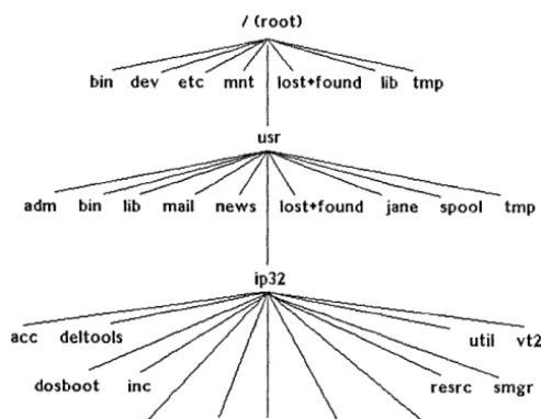
File System Structure
Commonly Referenced File Systems and Directories Pathnames
Absolute Pathnames Relative Pathnames Manipulating Directories Home Directories
4.5.2
4.5.3
4.5.4
4.5.4.1
4.5.4.2
4.5.4.3
4.5.5
4.5.6
4.6
4.6.1
4.6.2
4.6.3
4.6.4
4.6.5
4.6.6
4.6.7
4.7
4.7.1
4.7.1.1
4.7.1.2
4.7.2
4.7.2.1
4.7.2.2
4.7.2.3
4.7.3
4.7.3.1
4.7.3.2
4.7.3.3
Working Directories Changing Directories Listing Directory Contents Long Listing
Common 1s Command Options Long Listing Examples
Creating Directories Removing Directories Manipulating Files Naming Files
Displaying File Contents Copying Files
Moving Files Removing Files Using Wildcards
Taking Filename Shortcuts File Access and Permissions Fields in a Long Listing File Type
File Permission Mode
Determining Your User Type User (Owner) Category Group Category
Other Category Permission Modes Read Access Vol rite Access Execute Access
Chapter 5: Common Text Editors
5.1
5.1.1 5.1.2 5.1.3 5.1.4 5.1.5 5.1.6 5.1.7 5.1.85.1.9
5.2
5.2.1 5.2.25.2.3
5.2.45.2.5
5.2.6
The Intergraph MicroEMACS Product
Creating, Editing, and Exiting MicroEMACS Files Changing Modes
Moving the Cursor
Searching and Replacing Text Deleting Text
Inserting Spaces, Blank Lines, and Files Cutting and Copying Text
Changing Cases
Miscellaneous Commands vi and vedit
Creating, Entering, and Exiting vilvedit Files Changing Modes
Cursor Movement Commands Deleting Text
Replacing Text
Searching for Text Strings
xxxii
5.2.7
Copying, Moving, and Appending Text5-12
5.2.8
Setting Default Options 5--145.2.9
Miscellaneous Commands5-15
Chapter 6: Basic Network Communication
6.1
General Network Information6-3
6.1.1
Physical Components6-3
Coaxial Cable
6-3
Transceiver
6-3
Transceiver Cable
6-3
Ethernet Multiplexer
6-4
Etherjack
6-4
6.1.2
Network Configurations6-4
6.2
Workstation Preparation6-7
6.2.1
Network and Node Addresses6-7
6.2.1.1
Network Address Example6-7
6.2.1.2
Accessing a Network Address6-7
6.2.1.3
Storing a Network Address on an Intergraph Workstation6-8
6.2.2
Nodenames6-8
6.2.2.1
Accessing a Nodename6-8
6.2.2.2
Locating Other Nodenames in a Network6-9
6.2.2.3
Assigning a Nodename to a Workstation6-9
6.2.2.4
Assigning a Nodename to an InterServe Processor6-10
6.3
Network Communications6-11
6.3.1
File Management Utility6-11
6.3.1.1
Starting fmu6-11
6.3.1.2
Issuing fmu Commands6-12
6.3.1.3
Accessing Help for Imu Commands6-12
6.3.1.4
Exiting fmu6-12
6.3.1.5
Available Commands6-12
6.3.2
The visit Program6-14
6.3.3
Intergraph Network Core Monitor6-16
6.3.3.1
General Statistics Menu6-17
6.3.3.2
Loopback Test Menu6-17
6.3.3.3
Search Network Menu6-17
6.3.3.4
Routing Information Menu6-17
6.3.3.5
XNS Network Topology Menu6-18
6.3.3.6
MUltiple Node Analysis Menu6-18
6.3.3.7
Clearinghouse6-18
6.4
Additional Network Capabilities6-19
Chapter 7: Queuing and Printing
7.1
Understanding Queues7-3
7.1.1
Device Queues7-3
7.1.2
Pipe Queues7-3
xxxiii
7.2 Understanding Devices 7-4
7.3 NQS Command Overview 7-5
7.4 Displaying Queue Status Information 7-6
7.S Submitting Print Requests 7-7
7.6 qpr Examples 7-9
7.6.1 Submitting an ASCII Print File 7-9
7.6.2 Submitting a Plot Request 7-10
7.7 Deleting a Request 7-12
Chapter 8: The Floppy Disk Drive
8.1 Specifying Storage Capacity 8-3
8.2 Maintaining Floppy Disks 8-4
8.3 Inserting and Removing Floppy Disks 8-S
8.3.1 Inserting and Removing 31/2-Inch Floppy DiC)ks 8-S
8.3.2 Inserting and Removing S1/4-Inch Floppy Disks 8-5
8.4 Interpreting the Disk Activity Light 8-6
8.5 Accessing the Floppy Disk Drive 8-7
8.6 Formatting the Floppy Disk 8-8
8.6.1 Formatting from the Command Line 8-8
8.6.2 Formatting from the Utility Pages 8-9
8.7 Creating a Floppy Disk File System with the mkfs
Command 8-10
8.8 Copying One Floppy's Contents to Another with the
cpflop Command 8-12
8.9 Writing to Sequential Floppies with the fr_flop
Command 8-13
8.10 Reading from Sequential Floppies with the fr_flop
Command 8-14
8.11 Backing Up with the tar Command 8-15
8.12 Backing Up with the cpio Command 8-17
Chapter 9: Too1box Utilities
9.1 Toolbox Overview 9-3
9.2 The Clock Utility 9-4
9.2.1 Displaying the Clock 9-4
9.2.2 iclock Command-Line Options 9-4
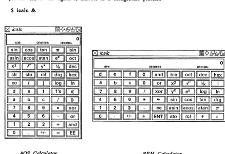
9.3 The Calculator Utility 9-6
9.3.1 Displaying the Calculator 9-6
9.3.2 Using the Calculator 9-7
9.3.3 icalc C.(}mmand-Line Options 9-7
9.3.4 Additional Functions 9-7
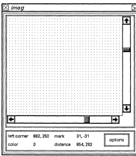
9.4 The imag Utility 9-9
9.4.1 Creating and Manipulating the imag Window 9-9
9.4.2 Moving the imag Window 9-10
xxxiv
9.4.4 9.4.5 9.5 9.5.1 9.5.2 9.5.3 9.5.4 9.5.5 9.5.6 9.6 9.6.1 9.6.2 9.6.3 9.6.3.1 9.6.3.2 9.6.4 9.7 9.7.1 9.7.2 9.7.3 9.7.4 9.7.5 9.7.6imag Options
imag Information Fields The colormap Utility Entering colormap
RGB and HSV Color Systems The Options Menu
Editing Colors in the Table Interpolating
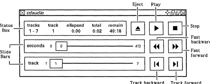
Using the File Menu The cdaudio Utility Entering cdaudio
cdaudio Command-Line Options Using the cdaudio Interface Status Box Fields
Slide Bars
Suggestions for Using cdaudio The iedit Utility
Creating an iedit File Inserting Text with iedit Editing Text with iedit Saving Files with iedit iedit Command-Line Options Upcoming iedit Features
Figures
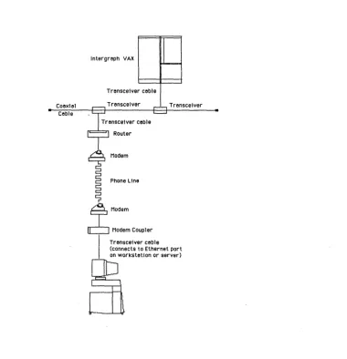
6-1
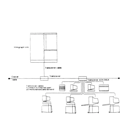
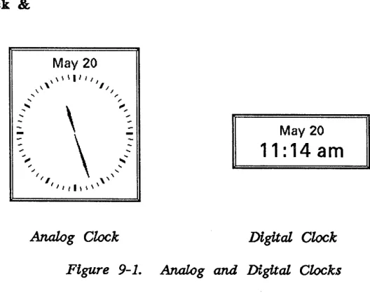
6-2 9-1 9-2 9-3
9-4
9-5
An Intergraph Workstation Connected to a Remote Ethernet Net~ork
Intergraph Workstations and Servers Connected to an EMUX. Analog and Digital Clocks
AOS and RPN Calculators The imag Windo~ The cdaudio Interface iedit Icons
xxxv
6-5 6-6
9-4
9-6
9-9
Chapter 1: Power-up, Reboot, and Shutdown Procedures
Chapter 1:
Power-up. Reboot and Shutdown Procedures
This chapter provides you with the basic information needed to tum on, reboot, and shut down your workstation or server. If you need to reboot or shut down at any point in this guide, refer to 1.2, "Rebooting," and 1.3, "Shutting Down the System."
This chapter includes the following sections:
1.1 1.1.1 1.1.2 1.1.3 1.1.4 1.1.5 1.2 1.2.1 1.2.2 1.2.3 1.2.4 1.3
1.3.1
1.3.2Powering Up
Turning on the Workstation or Server Introductory Screen for Workstations Introductory Screen for Servers
Loading the System V Operating System for Workstations Loading the System V Operating System for Servers Rebooting
Cold and Warm Boots
Reboot Procedure for Workstations Reboot Procedure for Servers
Using the BootlReboot Button or Restart Switch Shutting Down the System
Shutting Down the Workstation Shutting Down the Server
Power-up, Reboot, and Shutdown Procedures 1-3
1.1
Powering Up
This section explains the steps involved in powering up your workstation or server.
Note:
Refer to 1.3, "Shutting Down the System," before turning off your workstation or server.
1.1.1 Turning on the Workstation or Server
Use the following procedure that is appropriate for your type of workstation or server to locate the power switch and tum on the unit. The initial beep after the unit is powered on indicates that the keyboard is working.
• InterPro Desktop Workstations. The power switch is on the front of the base· between the keyboard plug and the floppy disk drive. Press the power switch to 1 (on).
• InterPro Workstations with Electronics Cabinet. Locate the power switch on the front panel of the electronics cabinet. Insert the key and tum the keyswitch to the ON or NORMAL setting.
• InterAct Workstations. The power switch is on the lower front right comer of the monitor head. Press the power switch to 1 (on).
• Standard InterView Workstations. The power switch is on the front right comer of the boom assembly. Press the power switch to 1 (on).
• Desktop interView Workstations. The power switch is on the front of the electronics cabinet. Insert the key and tum the switch to the ON or NORMAL setting.
• InterServe Processors. The power switch is on the front of the unit. Insert the key and tum the keyswitch to the ON or NORMAL setting.
You can purchase the CIT terminal to use with an Inter Serve processor. The terminal's power switch is in the lower right comer of the video screen. Press the switch to tum it on.
1-4 Power-up, Reboot, and Shutdown Procedures
Note:
Any devices connected to the R8-232 port must either be online or turned off when power-up diagnostics run. Diagnostics could fail if an R8-232 device, such as a printer, is offline. If diagnostics fail, turn the RS-232 device off and then perform a warm boot using the Boot button on the back of the workstation or server keyboard.
For more information, refer to 1.3, "Rebooting." Once the workstation is rebooted, turn the R5-232 device back on.
If all diagnostic software is not loaded on the workstation or server, the following message may appear at the end of the diagnostic test messages. This is not an error. The system will continue the power-up process.
Diagnostics boot failure
When you use a floating menu, if the cursor is on the floating menu instead of the digitizing table, the following message may appear under the Digitizer portion of the download diagnostics. This is not an error and will not jeopardize system performance in any way.
Mux Gain Bit not set, but coil was found
If the cursor is placed directly on the digitizing table, this message (which also is not an error message) appears:
The Table is a high Gain table
1.1.2 Introductory Screen for Workstations
When the diagnostic tests are complete, a blue introductory screen displays the Intergraph logo. The buttons at the bottom of the introductory screen are used to select the operating system, access the Utility pages, or access Help for these selections. The Utility pages are a series of menus used to configure the workstation system ports, hard disk, screen, and peripherals.
When the introductory screen displays, the screen cursor appears over the screen button for System V, the default operating system.
Power-up, Reboot, and Shutdown Procedures 1-5 1..1.3 Introductory Screen for Servers
When the diagnostics are complete, the following message appears:
Intergraph Corporation InterServe 200
Strike any key within 5 seconds to Access Startup Utility Menus.
Press any key on the terminal keyboard within five seconds to access the Utility Pages. Or, do not press any key to boot into the System V operating system.
1.1.4 Loading the System V Operating System for Workstations
When the System V operating system starts to load, the blue introductory screen disappears and the screen displays boot-up messages similar to the following:
UNIX System V Release 3.1 Clipper version 0 made 7124/89
Nodename
Swap Space • 24242 blocks
Total real mem • 6283264 bytes Available mem • 4915200 bytes
Copyright (c) 1989 AT&T - All rights reserved
The system is coming up. Please wait.
The system is ready.
1.1.5 Loading the System V Operating System for Servers
When the System V operating system starts to load, the introductory screen disappears and power-up diagnostics display. Mter the System V software has been loaded, you will receive a console login prompt.
Note:
For information on rebooting and shutting down InterServe processors, refer
1-6 Power-up, Reboot, and Shutdown Procedures
1.2
Rebooting
This section covers the procedures for rebooting the workstation or server.
1.2.1 Cold and Warm Boots
Rebooting the workstation or server reloads the system software. There are two types of boots: a warm boot and a cold boot. A warm boot typically refers to rebooting when the system is currently up, and a cold boot refers to booting when the system is not up. A warm boot simply reloads the software, while a cold boot performs diagnostic tests and reloads the software.
A reboot is needed under the following conditions:
• If you need to access the utility pages
• If the system will not accept cursor or keyboard input
1.2.2 Reboot Procedure for Workstations
When you need to reboot your workstation, follow these steps:
1. Log out of your user account.
2. If the console window has been deleted, create a new one.
3. Select the reboot option from the workstation menu.
4. A pop-up menu prompts you to confirm your request. Select OK to proceed.
1jL3 Reboot Procedure for Servers
When you need to reboot your server, follow these steps:
1. Log out of your user account and log in to the root account. 2. Key in reboot and messages similar to the following then appear:
Init: New run level: 1
REBOOT PROGRAM
Process acoou.nting stopped.
Error logging stopped.
Syncing disks • • • System reboot in progress
Power-up, Reboot, and Shutdown Procedures 1-7
The system beeps and then reboots. For workstations, select the desired screen button when the introductory screen appears. For servers, select the desired option when the Start-Up Configuration Utility menu appears.
1.2.4 Using the Boot/Reboot Button or Restart Switch
When possible, use the previous procedures to reboot the system. The reboot program syncs the disks and thus ensures an orderly halt for any processes that were running. Syncing the disks transfers all information stored in memory to the disks. Also, with these reboot procedures, the system bypasses file system checks for the next boot, which thereby shortens boot time.
However, if using the previous reboot options is not possible, boot by using the following procedure that is appropriate for your type of workstation or server:
• InterAct, InterView, and InterPro Desktop Workstations. Press the Boot button on the back of the workstation keyboard.
• InterServe 200 and InterPro 245. Press the Reboot button beside the keyswitch on the front of the electronics cabinet.
• InterServe 300, 305, and 400, InterPro 340 and 360, and 3000- and 4000-Series Workstations/Servers. Tum the keyswitch on the front of the cabinet to Restart and then return it to On or Normal.
• InterPro 6000. The keyswitch is on the front of the electronics cabinet. Keyswitch settings beginning at the top and moving clockwise to the bottom are as follows: 0 represents the off position, the triple-monitor icon is inactive at this time, 1 is the on position, and the 1 surrounded by a circular arrow is the restart position. To reboot the workstation/server, tum the keyswitch from the on position clockwise to the restart position and then tum it back to the on position.
Note:
1-8 Power-up, Reboot, and Shutdown Procedures
1.3
Shutting
Down
the System
Shutting down consists of shutting down the operating system properly and then switching off the power. Following the proper shutdown procedure is essential to protecting your workstation or server.
The system shutdown procedure accomplishes the following:
• Stops any running processes
• Syncs the disks, ensuring that all information stored in memory is transferred to the disks
• Parks the heads on all hard disks
• Halts the system
Properly shutting down bypasses the file system checks the next time the workstation or server is powered up, which thereby decreases the normal power-up time.
Notes:
• Always use the system shutdown procedure to ensure that the hard disk has been synced and the heads parked. Failing to sync the disks and park the heads could corrupt the file system .
• If you have a 6000-series workstation or server, turning the keyswitch to the off (0) position causes the system to perform an orderly shutdown automatically. Therefore, for these workstations/servers, you do not need to use the shutdown procedure.
1.3.1 Shutting Down the Workstation
Follow these steps to shut down the workstation:
1. Log out of your user account.
2. If the console window has been deleted, create a new one.
3. Select the shutdown option from the workstation menu.
4. Select the OK screen button when the pop-up menu appears and prompts you to confirm the request to power down.
1.3.2 Shutting Down the Server
Follow these steps to shut down the server:
Power-up, Reboot, and Shutdown Procedures 1-9
2. Key in shutdown.
Messages similar to the following then appear on the screen:
INIT: New run level: 0
SHUTDOWN PROGRAM
Process accounting stopped. Error logging stopped.
All currently running processes will now be killed.
Syncing disks • • • Parking heads • • •
SCSI ID 0, LUN 0 : heads parked System halted • • •
After these messages appear, tum the unit off by pressing the power switch to
o
(off) (on workstations without an electronics cabinet) or turning theChapter 2: Input Devices
Chapter 2:
Input Devices
Intergraph workstations provide two devices for data input and manipulation: the keyboard and cursor. This chapter explains each input device in detail and is divided as follows:
2.1 2.1.1 2.1.2
2.1.3
2.1.4
2.2 2.2.1 2.2.2 2.2.2.1 2.2.2.2
The Keyboard Typewriter Keys Numeric Keypad
Terminal Emulation Function Keys Application Function Keys
The Mouse/12-Button Cursor Using the Mouse
Using the 12-Button Cursor Moving the Cursor
Learning the 12-Button Cursor Assignments
2-3
2-4
2-4
2-4
2-4
2-5 2-5
Input Devices 2-3
2.1
The Keyboard
Each Intergraph workstation uses the same multipurpose keyboard. This section provides an overview of the layout and multiple uses for each key grouping.
• Typewriter keys • Numeric keypad
• Terminal emulation function keys • Application function keys
The layout of the workstation keyboard is shown below. The workstation keyboard interprets user input according to the active emulation.
Terminal
Emulation Application function Keys
Typewriter Keys
...
!'It...
~II "
UI II
.
..
UI.
lei r.w..c rtt LlLZ LI Li'
7 8
q--=-4 5 s ;
-2 3
-Numeric Keypad
When the workstation operates under System V, the keyboard emulates the following:
•
•
•
A VT220™ terminal keyboard when the VT220 emulation _process \s active. l VT220 PF keys are prmted in black on the left side of tlie keys.)
An InterAct graphics terminal keyboard when the InterAct Emulation process is active.
2-4 Input Devices
2.1.1 Typewriter Keys
The typewriter keys are used to key in alphanumeric data. They provide all upper- and lowercase letters, numerals, and symbols found on a standard ANSI typewriter.
2.1.2 Numeric Keypad
The numeric keypad provides an alternate way to key in numbers and has keys for special VT220 and IDM PC functions. See your CLIPPER System
Administrator's Guide for details. 2.1.3 Terminal Emulation Function Keys
The terminal emulation function keys are reserved for special terminal-related functions, such as the editing commands found on a VT220 terminal. Some keys are also for general functions, such as Help and setup. Eight keys are used specifically as function keys, while <2nd F> is a shift key.
Pressing the <2nd F> key before pressing another terminal emulation key initiates a secondary function, thereby doubling the number of functions available from this group of keys. See your CLIPPER System Administrator's Guide for details on how to use the terminal emulation features of your keyboard.
2.1.4 Application Function Keys
The application function keys are programmable membrane keys with functions that depend on the application program you are running. You can program them to serve as a function key menu for V AXTM.-based and standalone applications.
Input Devices 2-5
2.2
The Mouse/12-Button Cursor
Each workstation comes with a hand-held cursor. Your workstation will have either a mouse or 12-button cursor. This section covers both types of hand-held cursors.
2.2.1 Using the Mouse
The mouse is used (primarily with the InterPro workstation) to control screen cursor movement. The friction tracking ball on the underside of the mouse detects any motion and moves the cursor accordingly. Since the mouse is a cumulative (relative) tracking device, the cursor remains stationary when the mouse is picked up. This allows you to move the screen cursor around the screen using minimal desktop space.
For the best results from your mouse, follow these maintenance tips:
• Keep the mouse clean.
• Use light pressure when rolling the mouse. • Keep the buttons facing straight ahead.
Throughout workstation documentation, you will commonly
see
the term select.Select always means to place the screen cursor over the desired option and tap the middle button.
The following table lists the general uses for mouse buttons. Because each application may use the
mouse
buttons differently, always check the application documentation for a description of the mouse button assignments.Tap the_
Left (command) button
Middle (data) button <D>
Right (reset) button <R>
To ...
Invoke hierarchical menus
Select options from any menu or tutorial on the screen (including hierarchical)
Select icons and graphical elements Manipulate windows
Place data points
Identify graphical elements Activate windows (processes)
Cancel commands Reset commands
Reject element selections
2-6 Input Devices
Note:
The three mouse buttons function exactly the same as the top row of buttons on the 12-button cursor.
2.2.2 Using the 12-Button Cursor
The 12-button cursor is an absolute tracking device used to move the screen cursor and to select from menus on the screen and digitizing surface.
2.2.2.1 Moving the Cursor
Screen cursor movement is controlled by movement of the 12-button cursor over an area of the digitizing table that corresponds to the area of the screen. This area of the digitizing table is called the tracking area. Depending on the size of your table, the entire area within the dark border around the edge of the table is active .
.As you move the cursor in this area, notice that the screen cursor moves about two inches for every inch of cursor movement. This cursor movement feature allows you to control both screens with relatively short arm motions. It also leaves more of the digitizing table surface available for other purposes.
Note:
Some applications may redefine the tracking area size and location.
2.2.2.2 Learning the 12-Button Cursor Assignments
Throughout workstation documentation, you will commonly see the term select.
Select always means to place the screen cursor over the desired option and tap the middle <D> button.
Tap the_
Left button
Middle button
Right button
Second row, middle button Second, third, fourth rows buttons 1-8
Note:
Input Devices 2-7
- Invoke hierarchical menus
- Select commands from a paper or matrix menu
- Select options from any menu or tutorial on the screen (including hierarchical)
- Select icons and graphical elements - Manipulate windows
- Place data points
- Identify graphical elements - Activate windows (processes)
- Cancel commands - Reset commands
- Dismiss pull-down and hierarchical menus - Reject element selections
- Place tentative data points
Select user-defined commands that have been assigned to these buttons
Chapter 3: The Screen Display
Chapter 3:
The Screen Display
This chapter acquaints you with the basic screen components, windows, and menus available with Intergraph workstations. The following sections are included:
3.1
3.2 3.2.1 3.2.2 3.2.3 3.2.43.3
3.3.1 3.3.2 3.3.3 3.3.4 3.4 3.4.1 3.4.2 3.4.2.1 3.4.2.2 3.4.2.3 3.4.2.4 3.4.2.5 3.4.2.6 3.4.2.7 3:4.2.8 3.4.2.9 3.4.2.10 3.4.2.11 3.4.2.12 ·-3.4.2.13 3.4.2.14 3.4.2.15 3.4.3Entering the System Through the Workstation Login Menu Understanding the Screen Display
Message Strip Console Window Local Window Screen Working Area Using the Screen Display Understanding the Process ID Using the Workstation Icon
Using the Primary Screen Icon for Dual-Monitor Workstations
Using the Virtual Screen Icon for Single-Monitor Workstations Interacting with Windows
Active Processes
Window Manipulations Moving a Window
Moving a Window from One Screen to Another Using Dual-Monitor Workstations
Modifying a Window
Popping a Window to the Top/Bottom of a Window Stack Collapsing a Window
Moving a Collapsed Window Restoring a Collapsed Window Deleting a Window
Repainting a Window Using the Setup Icon Using the Catalog Icon Using the Reset Icon U sing the Resize Icon U sing the Clear Screen Icon Using Copy and Paste Icons Scrolling Windows
3-2 The Screen Display 3.5 3.5.1 3.5.2 3.5.2.1 3.5.2.2 3.5.2.3 3.5.2.4 3.6 3.6.1 3.6.2 3.6.3 3.6.4 3.6.5 3.6.6
Screen Menus and Menu Options Pull-Down Menus
Pop-Up Menus Data Entry Boxes Checkboxes Screen Buttons Hierarchical Menus
Other Menus and Displays Window Menus
Function Key Menus Paper Menus
Roll-through Boxes Toggle Switches Alert Boxes
The Screen Display 3-3
3.1
Entering the System Through the Workstation Login Menu
As a security feature for Intergraph systems, the follovling login menu appears after the system boots. You are required to enter the username and password for any user account on the system before windows will be created.
Workstation User
r
MessagesPlease enter Username and Password
User Name 1 - 1 _________- - - '
Password ... 1 _ _ _ _ _ _ _ _ _ ----'
D
Execute Default Processes8]1~1
This new login menu establishes a system user. All processes executing on the system will run under the protections/privileges established by the system user. A new entry in the Workstation Pulldown Menu (Wkst. User) can be used to check for the current system user. When you are finished using a system, use the log out fea.ture on the Workstation Pulldown Menu.
If you want to bypass this menu and log directly in to the windowing
environment of your workstation, you can edit the /usr/ip32/smgr/wkstuser file. Enter the login name of a user account in this file; only
one
login name can appear in this file. The system will boot directly into Screen Manager through the user established in this file instead of requesting a user login through the login menu.Caution:
You will forfeit the security advantages of the login menu if you choose to bypass it with this method.
3-4 The Screen Display
3.2
Understanding the Screen Display
Mter you enter the correct username and password on the Workstation User menu, the menu disappears and the standard workstation screen display (created by the Screen Manager software) appears. This section introduces the following basic features of the screen display:
• Message strip • Consoie window • Local window • Screen working area
3.2.1 Message Strip
At bootup, the Screen Manager software automatically initializes the message strip and creates a local and console window. The message strip is composed of the following:
workstation
icon
l
~g~:~y messalge area pr~ocess ID iconJL ________
~________ __
Icl¢I---I
ttxOOI
You can move the message strip from the top of the screen to the bottom by selectinv& the process ID field. Remember, select means to place the screen cursor over the desired element and tap the middle <1» button.
Note:
If you are using a single-monitor workstation, the virtual screen icon replaces the primary screen icon.
The Screen Display 3-5
The virtual screen icon appears as follows:
The workstation icon is selected to display the workstation menu. From this menu you can create a terminal window and connect to a host computer, create a local window to access the System V operating system, run a process, or modify the workstation pull~own menu.
The virtual screen icon (on single-monitor workstations) is used to choose between virtual screens. The two virtual screens provide you with two different working areas. For example, you could run a graphics application program on one virtual screen and compile a program on the other. Selecting the virtual screen icon allows you to toggle between virtual screens.
The primary screen icon (on dual-monitor workstations) is used to choose a primary screen. Selecting this icon changes the direction of the arrow, thus establishing the primary screen. When the arrow points to the right, windows you create appear on the right screen. When the arrow points left, they appear on the left screen.