Scalability Issues in Cluster Web Servers
Arkaitz Bitorika
A dissertation submitted to the University of Dublin,
in partial fulfillment of the requirements for the degree of
Master of Science in Computer Science
Declaration
I declare that the work described in this dissertation is, except where otherwise stated,
entirely my own work and has not been submitted as an exercise for a degree at this or
any other university.
Signed: _____________________ Arkaitz Bitorika
Permission to lend and/or copy
I agree that Trinity College Library may lend or copy this dissertation upon request.
Signed: _____________________
Arkaitz Bitorika
Contents
1 Introduction 7
2 State of the Art Overview 10
2.1 Web Serving Overview . . . 10
2.2 Cluster architecture . . . 12
2.2.1 Layer 4 switching with layer 2 forwarding . . . 12
2.2.2 Layer 4 switching with layer 3 forwarding . . . 13
2.2.3 Layer 7 switching . . . 14
2.3 Server selection / request distribution . . . 17
2.3.1 DNS Round Robin . . . 17
2.3.2 Weighted Round Robin (WRR) . . . 18
2.3.3 Weighted Least Connections . . . 19
2.3.4 LARD . . . 19
2.3.5 WARD . . . 24
2.3.6 PPBL . . . 25
2.4 Web caching replacement policies . . . 26
2.4.1 Least Recently Used (LRU) . . . 27
2.4.2 Least Frequently Used (LFU) . . . 28
2.4.3 Hyper-G . . . 28
2.4.4 Pitkow-Recker . . . 29
2.4.5 Hybrid . . . 29
2.4.6 Lowest Relative Value (LRV) . . . 29
2.4.7 GreedyDual-Size . . . 30
3 Design and implementation 31 3.1 Architecture . . . 32
3.2 Inter-process communication . . . 35
3.2.1 RMI protocol . . . 35
3.2.2 Socket-based application-specific protocol . . . 36
3.3.1 Thread-per-connection model . . . 37
3.3.2 Event-driven model with multiplexed I/O . . . 38
3.4 Front-end . . . 41
3.4.1 Multi-threaded socket listener . . . 42
3.4.2 Reactor-based socket listener . . . 44
3.4.3 Dispatcher . . . 46
3.5 Cache Manager . . . 47
3.6 Node Manager . . . 48
3.6.1 Caching . . . 50
4 Evaluation 52 4.1 Test setup and methodology . . . 52
4.1.1 WebStone . . . 53
4.2 Traces . . . 54
4.3 Evaluation results . . . 55
List of Figures
2.1 Example URL division. . . 11
2.2 Web server address resolution steps. . . 11
2.3 Layer 4/2 cluster architecture . . . 13
2.4 Layer 4/3 cluster architecture . . . 14
2.5 TCP gateway operation . . . 15
2.6 Architecture of split connection application layer dispatchers. The proxy or dispatcher keeps open TCP connections both with the client and with the server. . . 16
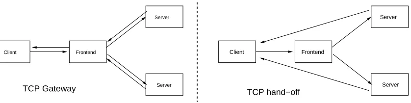
2.7 Architecture of a dispatcher or layer 7 proxy using TCP splice. The re-quest data that moves between client and server is kept at the kernel level. 16 2.8 Traffic flow in TCP gateway versus TCP hand-off . . . 17
2.9 LARD operation . . . 19
2.10 Pseudo-code for the basic LARD request distribution algorithm. . . 20
2.11 LARD with Replication . . . 21
2.12 Centralised dispatcher and distributor . . . 23
2.13 Scalable LARD cluster architecture . . . 23
3.1 Common Web cluster deployment scenario. . . 32
3.2 Logical view of the components in a running cluster. . . 33
3.3 Physical view of the components in a running cluster. . . 34
3.4 Structure of the messages sent from the front-end to the node managers. . 37
3.5 Thread-per-connection model. . . 38
3.6 Single threaded event-driven model with multiplexed I/O. . . 39
3.7 Class diagram of main participants in the Reactor pattern. . . 40
3.8 Multi-threaded listener class diagram. . . 42
3.9 Sequence diagram for RequestHandler thread. . . 43
3.10 ReactorListener class diagram. . . 45
3.11 IDispatcher interface class hierarchy. . . 46
3.12 CacheManager class diagram. . . 48
3.13 Node manager class diagram. . . 49
4.1 Connections per second with dynamic traffic. . . 56
4.2 Connections per second with static traffic. . . 57
4.3 Throughput with dynamic traffic. . . 58
4.4 Throughput with static traffic. . . 59
4.5 Average response times for dynamic traffic. . . 59
Chapter 1
Introduction
The World Wide Web is probably the most popular application running on the Internet,
and the traffic generated by the ever growing number of users on the Web forces Web sites
to implement scalable Web server architectures that will be able to handle current loads
as well as grow to meet future performance requirements.
Cluster Web servers are a popular solution for building scalable Web serving
plat-forms, they offer a cost-effective alternative to high-end servers and can be built from
relatively economical hardware and software. State-of-the-art commercial Web
cluster-ing products employ a specialized front-end node that is a scluster-ingle point of contact for
Web clients and distributes HTTP requests to the back-end nodes in the clusters.
Back-end nodes are typically standard Web servers than can be built with common of-the-shelf
(COTS) hardware and run a Unix-like or Windows operating system. The front-end node
is normally a device that integrates proprietary hardware and software from a commercial vendor.
Web clustering front-ends can be broadly divided in layer 4 and layer 7 switches or
dispatchers. Layer 4 refers to the OSI network protocol layer 4, TCP in TCP/IP networks,
and means that the front-ends can only use TCP information for taking request distribution
requests. In layer 7 switches the front-ends are application layer information aware, the
application being HTTP in the case of Web servers. Access to HTTP information such as
the request URL, file type or cookies sent by the Web browser allows for a more effective
and flexible configuration of the cluster. For example, layer 7 front-ends can dispatch
all requests for a certain kind of file type to a specific server, or when used with Web
application servers, send all the request with the same session cookie to the back-end server that has the relevant session data in main memory.
However, state-of-the-art Web clustering solutions achieve only limited scalability ,
and offer a solution based on embedded hardware and software that does not integrate
well with, and take advantage of, existing Web server and application software. The
integrate with the back-end nodes’ software as they have to offer a solution that is as
“standalone” and “plug and play” as possible. Most clustering products don’t work as
an integrated whole, they are implemented as separate front-ends or Web switches that
“clusterise” a set of back-end Web server nodes.
The requirement for Web cluster front-ends to be transparent to the back-end nodes
has important scalability implications when layer 7 switching is used. The front-end has
to accept TCP connections and read their HTTP request data, tasks that were previously performed by the back-end Web server. This extra work can make the front-end become
a bottleneck, and with front-ends that are transparent to the back-end servers the HTTP
request decoding is done once more by the back-end Web server as well.
In this dissertation a Web cluster architecture is designed, implemented and evaluated.
We believe that with the use of COTS hardware and integrated front-end and back-end
software better scalability and flexibility can be achieved for Web clusters. Furthermore,
the clustering software is all implemented in Java, with the goal of evaluating Java as a
platform for the implementation of high-performance network servers. The Web cluster
prototype described here is built out of a set of distributed components that collaborate
to achieve good scalability as a Web server. As all the components have been designed from scratch to integrate with each other and work well together, the scalability problems
associated with state-of-the-art content-aware commercial clusters are avoided.
The prototype Web cluster described in this dissertation will be evaluated using
pub-licly available Web benchmarking tools and Web access-log traces. Different workloads
will be applied to the cluster as well as to a standalone Java Web server to compare their
performance and scalability. Web clustering research has frequently assumed that the
Web traffic is mostly static, that is, mainly composed of requests for static files. However,
more and more Web sites implement dynamic Web applications and there is a tendency toward completely dynamic sites. Thus, apart from standard static traffic dynamic Web
traffic is also simulated and evaluated in our tests.
The evaluation results show that a differentiation between static and dynamic
re-quests is necessary for better understanding of Web server scalability issues. When
han-dling static traffic, it is easy for a single node Web server to saturate an Ethernet 100
Mbit/second connection, and I/O throughput is the main factor. However, scalability of
Web servers that handle dynamic traffic is much improved from using a clustering
ap-proach. This is due to the fact that when serving dynamic requests I/O performance is not
the main scalability factor and CPU processing becomes very important as well.
Further-more, issues involved in implementing scalable network servers in Java are discussed as well, focusing specifically on how the new non-blocking I/O facilities affect the
architec-ture and scalability of server applications.
overview of Web clustering, chapter three discusses the design and implementation of
an scalable Web cluster in Java, chapter four evaluates the performance and scalability of
Chapter 2
State of the Art Overview
2.1
Web Serving Overview
URLs are the most user-visible component of how the World Wide Web (Web) works.
When a user wants to retrieve a Web page, all the necessary information for contacting
the right Web server and making the appropriate request for the desired page is contained
in a URL that the user can type in the address bar of the browser. URLs are composed by
several parts as seen in figure 2.1, they are:
Protocol The protocol specifies which application layer (OSI layer 7) protocol the browser
will use to communicate with the server. In the case of Web connections, the
pro-tocol will normally be http for traditional clear-text requests or https for secure
en-crypted requests. These two are the standard Web protocols, but current browsers
usually understand others like ftp or mailto, even if they are not strictly part of the
Web.
Host The host name will specify which Web server a request is directed to. It is a
human-understandable name that will be translated to an IP address by the DNS naming
system used in the Internet. Once the browser obtains the IP address that the host
name belongs to using DNS, it can directly address the Web server host.
Port The port component of the URL is an optional part required by the underlying
net-work protocol layer, TCP. Even if the Web client will always use a port number
when connecting to the server, the port is optionally in the URL, as different proto-cols have well-known ports that are chosen by default if no specific port number is
given. For example, HTTP uses 80 as its well-known port number.
File path It contains the path to a Web page or file in the Web servers file system,
ex-pressed in a form relative the document root of the Web server, not to the
conven-tions for separators. With the popularity of dynamic sites and Web applicaconven-tions,
the path frequently doesn’t specify the location of a physical file that exists on the
servers file-system, instead it serves more as a Remote Procedure Call that the Web
server will use to decide which part of the Web application logic to execute.
http://www.example.com:80/index.html
protocol://host:port/filePath
Figure 2.1: Example URL division.
The initial URL that the Web browser user types in an address bar will eventually be
mapped to a set of blocks in a file-system that a Web server process will read or a set of
instructions that will generate a dynamic response.
DNS Resolution
Host name IP address
ARP Resolution
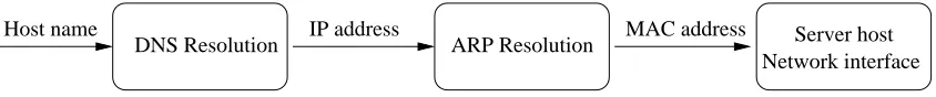
[image:12.595.89.511.335.379.2]Network interface Server host MAC address
Figure 2.2: Web server address resolution steps.
There are various steps in this process assuming that the final server is connected to
an Ethernet network (Figure 2.2):
DNS Resolution The Domain Name System (DNS) is the standard mechanism on the
Internet for resolving a given host or domain name to an unique IP adress. The IP
address identifies one physical machine connected to the Internet.
IP Routing When the Web browser obtains the IP address from the name resolution
sub-system, it sends an HTTP request to that IP address, by sending a set of IP packets
with the IP address of the host. These IP packets go through potentially several
hops between Internet routers until they reach the sub-network that is configured as
including the host with the IP address.
ARP Resolution When the request IP packets reach the last router before the host, the
router will resolve the IP address of the host to an Ethernet MAC address. A MAC
address is an unique identifier of the network card installed on the host. The
map-ping between IP and MAC addresses translates allows the Ethernet switch to send
the request packets to the right network interface connected to it.
Once the request IP packets arrive to the Web server host, they get reassembled to build
server will use then the standard operating system facilities to read the disk blocks needed
for obtaining the contents of the file.
This process has several steps in which a resolution of a mapping between different
naming or addressing schemes is performed: from host name to IP address, from IP
ad-dress to MAC adad-dress and from requested URL to file-system block. These points in the
process of handling a HTTP request are where Web clustering techniques can be
intro-duced. For example, DNS round-robin will resolve a given host name to one of several IP addresses available, or a Web server can cache files in main memory instead of loading
them from the file-system for each request. Several examples of cluster architectures are
discussed in the next section.
2.2
Cluster architecture
We will use a classification of different Web server clustering technologies that has been
proposed explicitly by Steve Goddard and Trevor Schroeder [32, 33], but is common
as well in the research literature. Most of the Web server clustering technologies are transparent to the client browsers, the browsers are at no time aware of the existence of
clustering on the server side. However, not all clustering technologies are transparent
to the web server software. While still being transparent to the clients, some clustering
solutions are visible to the Web servers, and need specialised software at different levels
in the server system.
2.2.1
Layer 4 switching with layer 2 forwarding
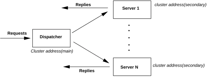
In L4/2 clustering, the dispatcher and the servers all share a common cluster network address (referred as “Virtual IP address” by some vendors). All incoming traffic for the
cluster address is routed to a dispatcher, using static ARP entries, routing rules, or some
other mechanism. All the servers have a primary unique IP address, but share the cluster
address with the rest of the servers and the dispatcher, which has the cluster address as its
main IP address.
When a packet arrives, the dispatcher determines whether it belongs to a currently
es-tablished TCP connection or is a new connection. If it is a new connection, the dispatcher
chooses one target server to satisfy the request according to its request distribution policy
and saves the mapping between the connection and the server in its memory. Then the
MAC (physical layer or layer 2) address of the frame is rewritten and the packet is sent to the chosen server.
The server receives the packet and it accepts it as the packet has the address of the
Dispatcher
Requests
.
.
.
.
.
Server 1
Server N
cluster address(secondary)
cluster address(secondary) Cluster address(main)
Replies
[image:14.595.128.465.79.205.2]Replies
Figure 2.3: Layer 4/2 cluster architecture
the servers’ default gateway, instead of going through the dispatcher, avoiding the
bottle-neck of passing all the traffic through the dispatcher. When the TCP connection gets drop, the dispatcher will delete the associated information from its memory.
This technique is very simple while still providing high throughput, as only the
incom-ing traffic is processed by the dispatcher. In typical Web traffic, replies account for most
of the data transmitted, and with L4/2 clustering the reply data is sent straight from the
server to the client. Moreover, as only layer 2 information is rewritten at the dispatcher,
there is no need to recompute TCP/IP checksums.
The drawback is that all the nodes have to be in the same switch as the dispatcher, due
to its use of layer 2 addressing, which is not usually a problem as clustered servers are usually interconnected by high-speed LANs, and it could be possible to use proprietary
solutions like Cisco switch-to-switch interconnects to propagate MAC address between
different switches.
Research prototypes of L4/2 clustering are ONE-IP [24] from Bell Labs and LSMAC
[20] from the University of Nebraska. Most of the commercial load balancing solutions
provide this kind of clustering as an option.
2.2.2
Layer 4 switching with layer 3 forwarding
It is also known as “Load Sharing Using Network Address Translation (LSNAT)”, and it is an Internet standard detailed in RFC 2391[30]. Examples of commercial
imple-mentations are Cisco’s LocalDirector 400 series [5], Foundry Networks’ ServerIron web
switches[11] and Nortel’s Alteon ACEdirector series [23]. A research prototype using it
is MagicRouter from Berkeley [22].
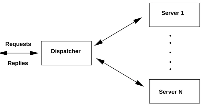
In L4/3 each server in the cluster has a unique IP address, and the dispatcher is the
only one that has the address assigned as the cluster address. When a packet arrives the
dispatcher, it rewrites the destination IP address to be the address of the chosen server out
of the cluster, recomputes necessary checksums, and sends it back to the network. When
servers using a request distribution algorithm, keeping the association between layer 4
connection and the server for all future packets part of the connection.
Dispatcher
.
.
.
.
.
Server 1
Server N Replies
[image:15.595.132.470.122.302.2]Requests
Figure 2.4: Layer 4/3 cluster architecture
The server processes the packet and sends the response back to the dispatcher. This
last step is necessary, as without changes in the network protocol, the server operating
sys-tem, or device drivers, the packet must be sent to the dispatcher, because the client expects
a reply from it. When receiving the response, the dispatcher changes the source address
from that of the responding server to the cluster IP address, recomputes checksums, and
sends the packet to the client.
It is well known that a L4/3 cluster will perform worse than a L4/2 architecture, due
to the workload imposed upon the dispatcher by L4/3. As all the traffic has to go through
it and it has to compute the checksums for each packet, the dispatcher becomes quickly a
bottleneck .
2.2.3
Layer 7 switching
Also known as content-based switching or content-aware request distribution, it operates
at the application layer (L7) of the OSI protocol stack. Commercial implementations
that have this functionality are Nortel’s Alteon ContentDirector [23], Foundry Networks’
ServerIron family [11]and Cisco’s CSS 11000 switches [5].
In an L7 cluster the dispatcher is a single point of contact for clients, similarly to the
layer 4 switching architectures. However, the dispatcher does not merely pass packets depending on a load balancing algorithm or which TCP connection they are from.
In-stead, the dispatcher will accept the connection and choose an appropriate server based
on application level information sent by the client in the request.
There are two main approaches to the handling of the connection once the target
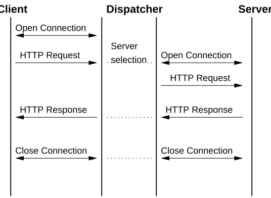
TCP Gateway
HTTP Response Open Connection
HTTP Request Open Connection
HTTP Request
HTTP Response
Close Connection Close Connection
Client Dispatcher Server
[image:16.595.162.430.112.308.2]Server selection
Figure 2.5: TCP gateway operation
In this case, once the dispatcher has decided which back-end server will handle the re-quest, a new TCP connection is established between the dispatcher and the server, and the
dispatcher acts basically as a TCP gateway, relaying the data between the server and the
client. This approach has similar problems to L4/3 switching, all data has to go through
two connections and TCP/IP protocol stacks, the first one between the client and the
dis-patcher and the second one between the disdis-patcher and the back-end server.There are
various optimisation techniques used with this architecture, connection pooling and TCP
splicing.
Connection Pooling
Creation of TCP connections is a time and resource consuming operation, to avoid this
time the dispatcher can “pre-fork” connections to the servers, keeping a pool of open
TCP connections that it can reuse. This way, once the target server has been chosen
the dispatcher simply picks an idle connection from the pool instead of establishing a
new connection with the server, avoiding the overhead of initiating a TCP connection for every new HTTP request. A research prototype of this design is used for Content-based
Routing[9].
TCP Splicing
Typically, proxies and load-balancing dispatchers that work at the application layer use
an architecture called split connection, where there is a connection between the client and
This scheme illustrated in figure 2.6 has important performance problems and violates
end-to-end semantics of TCP.
Interface Network
Client
Application Space
Kernel TCP/IP Stack
Proxy Server
client−proxy connection proxy−server connection
[image:17.595.131.466.124.300.2]Client application Dispatcher Server application
Figure 2.6: Architecture of split connection application layer dispatchers. The proxy or dispatcher keeps open TCP connections both with the client and with the server.
TCP Splice has been proposed by David Maltz [35] as an improved design for TCP
gateways. The basic idea behind TCP Splicing is shown in figure 2.7, the packets that
are subject to being forwarded can be modified as they are received without passing them
up and down through the whole TCP/IP stack. Once the dispatcher has set up the splice
for a given connection, all the packets that are part of this connection go through the
splice, without performing all the expensive data-copying operations caused by the transit
through the protocol stack.
Interface Network
Client
Application Space
Kernel TCP/IP Stack
Proxy Server
client−proxy connection proxy−server connection
Client application Dispatcher Server application
TCP splice
[image:17.595.128.467.497.674.2]TCP hand−off TCP Gateway
Client Frontend
Server
Server
Client Frontend
Server
[image:18.595.93.512.78.183.2]Server
Figure 2.8: Traffic flow in TCP gateway versus TCP hand-off
TCP Hand-off
This approach, illustrated by figure 2.8allows the dispatcher to give or “hand off” a TCP
connection to a particular server once it has decided which one of the servers is the right one to answer the request. In layer 7 switching clusters, dispatchers need to be able to fully
establish a TCP connection with the clients to receive the application layer (HTTP in this
case) request data that will allow them to make a choice regarding which back-end server
will deal with the request. Once the decision has been made, the dispatcher has to be able
to “re-establish” the connection on the back-end server, recreating the required connection
state. This protocol is extensively discussed in Thomas Larkin’s dissertation [18] and is
used in layer 7 designs like Content-Aware Request Distribution [4] or Locality-aware
Request Distribution [17]. Resonate [29] commercialises a proprietary solution that uses
this approach under the name of TCP Connection Hop in their Central Dispatcher product
[29].
2.3
Server selection / request distribution
2.3.1
DNS Round Robin
In a Server selection system that uses DNS, the DNS server will resolve the name of the service or domain to a different IP address using different algorithms such as load
average of a simple round-robin. This mechanism is specified in RFC 1974 [31]. DNS is
the naming system used in the Internet, as such it supports massive scalability by making
use of hierarchical organisation of naming information and caching at several levels of
the naming system.
DNS-based server selection techniques base their effectiveness on setting a very low
(down to 0) value for the TTL (Time To Live) field of their responses, minimising caching
of the name resolutions, which allows the implementation of round-robin or other load
balancing algorithms, as well as more complex solutions that try to resolve to IP addresses
control the back-end server to which each request gets sent.
The problem with this approach is that all the elements involved in resolving a name
to an IP address, from the browser to the root DNS servers, use caching for improving
performance and response times to users. Between DNS servers, the validity of a piece
of information is given by a TTL field that specifies how long that information can be
cached before refreshing it from the original or “authoritative” source, and web browsers
are known to cache resolution information for about 15 minutes. This caching at several layers is what makes DNS so scalable.
It has been shown in [10] that DNS-based server selection schemes actually have
a negative impact on client-perceived web access latency. Without caching, the client
should always need to contact the DNS server before each request, increasing name
res-olution overhead by up to two orders of magnitude. This problem is aggravated by the
delays caused by DNS queries needed for embedded objects in HTML pages such as
images.
2.3.2
Weighted Round Robin (WRR)
Weighted Round Robin (WRR) is the most common distribution algorithm found in com-mercial web load-balancing solutions, and although comcom-mercial vendors frequently
sup-port other more complex server selection schemes such as URL-aware selection, WRR
and its variants are still very popular and widely used, thanks to their simplicity and
scal-ability.
In this server selection scheme the front-enback-end dispatcher is usually a Layer
4 switch that distributes request to back-end servers using only load-balancing
require-ments. As its name implies, it is a variant of Round-Robin that instead of “blindly”
dis-patching requests iteratively to the available back-end servers, has a weighting introduced for each server, normally calculated as a function of the CPU, disk and/or memory use.
The weight of each server in the load-balancing algorithm is reevaluated periodically.
The main benefits of WRR are that it obtains low idle times in the back-end servers
and achieves a very well balanced load distribution. However, the main problem of WRR
is that it show a high cache miss ratio. In web servers, being able to cache the working set
(the set of web objects that the server accepts requests for) is critical, as the throughput of
the current disk devices is much lower than the expected throughput of network servers.
For web server clusters that have big working sets this supposes a problem, as each
in-dividual node main memory cache has to fit the entire working set, which is frequently
impossible. When the node caches are not able to hold all their working set, the through-put is low, as the cluster is not taking advantage of its aggregated cache size. WRR scales
well to high-traffic sites but doesn’t provide greatly improved response rates when the
Different distribution schemes based on Layer 7 switching try to overcome this
prob-lem by distributing requests to nodes that are more likely to already have the requested
object in the cache, effectively partitioning the working set and making it possible for
individual nodes to keep their respective partitions in cache. One example of this design
is Locality-Aware Request Distribution [17].
2.3.3
Weighted Least Connections
Weighted Least Connections (WLC), is a common alternative to WRR as a request
dis-tribution algorithm. It is a weighted variant of Least Connections (LC), which bases its
distribution decisions on the number of open TCP connections each back-end server has
open. The rationale behind this idea is that if the server has several open connections, it
means that it is busy servicing requests, and the more open connections it has, the less
new requests it should receive.
The weighted version of LL, WLC, goes one step further and includes a weight in the
distribution algorithm. This weight is calculated and updated the same way as with WRR,
using variables such as disk, CPU or network resources usage. This algorithm is available
for several load-balancing solutions, in software Linux Virtual Server [21] is an example and in hardware Cisco Catalyst web switches [5] provide it as well.
2.3.4
LARD
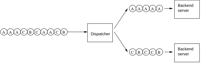
A A
A C B C A A C B
A A A A A
C B C C B
Backend
Dispatcher
server
[image:20.595.127.473.470.579.2]Backend server
Figure 2.9: LARD operation
Locality-aware request distribution (LARD) is a form of content-based request
dis-tribution described in [17]. It uses Layer 7/HTTP information. The main advantages of
content-based request distribution compared to schemes like WRR or WLC are:
1. Better throughput thanks to a lower number of main memory cache misses in the
back-end servers.
2. Ability to partition the working set over the different back-end servers, having more
3. Ability to use specialised back-end nodes for services like multimedia streaming or
dynamic web applications.
LARD focuses on obtaining the first of the advantages cited above, improved cache hit
rates. In figure 2.9 the operation of a basic locality-aware dispatcher is shown, by
dis-tributing requests in this way, there is the risk that the load on the back-end servers
becomes unbalanced, resulting in worse performance than with simpler round-robin
al-gorithms. Thus, LARD has to provide a solution that simultaneously achieves
load-balancing and high cache hit rates on the back-end servers.
Basic LARD
The basic version of LARD always assigns a single back-end server to handle a given
target/URL, effectively assuming that a the requests for a single URL can’t exceed the
capacity of a single server.
Figure 2.10 shows the pseudo-code for basic LARD. The dispatcher maintains a
one-to-one mapping of requested URLs to back-end servers in the server hash-table. When
a given URL is requested for the first time, the least loaded back-end server is assigned to it, and the decision is recorded. In subsequent requests for the same URL, the same
server will be assigned unless the server is overloaded, in which case the request will be
assigned to the least loaded node of the cluster.
The number of open connections are used to calculate the load on the back-end servers.
An overloaded server will have a higher number of open connections as it will not be able
to handle them quickly, while a lightly loaded node will have few or none active
connec-tions. This factor is the easiest way for the dispatcher to get load information from the
back-end servers without using explicit communication, but other systems that involve
communication could be used as well.
while (true)
request = fetch next request if (server[request] is null)
node, server[request] = least loaded node else:
node = server[request]
if ((node.load > Thigh and exists node with load < Tlow) or (node.load >= 2 * Thigh))
node, server[request] = least loaded node send request to node
Basic LARD considers only locality when partitioning the working set. It keeps this
strategy unless a “significant load imbalance” is detected, in which case it reassigns the
URL to a different back-end server. The algorithm to reassign an URL works as follows:
Tlow is defined as the number of active connections (load) below which a back-end server
will have idle resources and Thigh as the load above which the server’s response times will increment substantially. There are two conditions that can trigger a reassignment of
the URL to the least loaded node:
When a server has a load larger than Thigh wile another server has a load less than
Tlow.
When the server reaches a load of 2Thigh, even if no server has a load lower than
Tlow.
The two conditions try to ensure that the reassignment only happens when the load
dif-ference is substantial enough. To prevent the case in which the load on all servers rises to 2Thigh,causing LARD to behave like WRR, the total number of connections handed to the back-end servers is limited by the value S = (n - 1) * Thigh + Tlow - 1, where n is the number of back-end servers.
LARD with Replication
while (true)
request = fetch next request if |serverSet[request]| is 0:
node, serverSet[request] = least loaded node else:
node = least loaded node in serverSet[request] mostLoaded = most loaded node in serverSet[request]
if ((node.load > Thigh and exists node with load < Tlow) or (node.load >= 2 * Thigh))
p = least loaded node
add p to serverSet[request] node = p
if ((|serverSet[request]| > 1)and (time() -serverSet[request].lastMod > K))
remove mostLoaded from serverSet[request] send request to node
if (serverSet[request] changed in this iteration) serverSet[request].lastMod = time()
Figure 2.11: LARD with Replication
There is a potential problem with the basic LARD strategy: only one backend server
requests for a backend, it is possible that the backend gets overloaded, degrading
perfor-mance considerably. The solution is to allow several backend servers to handle a single
URL in a round-robin fashion. This is called “replication” in the LARD design, as the
objects are replicated in more than one server.
Figure 2.11 contains pseudo-code for this approach. The main difference is that the
dispatcher maintains a set of backend servers that handle each URL. Normally, the
re-quests are assigned to the least loaded node in the server set. In the case of a load imbal-ance occurring, the least loaded node from the cluster will handle the request and will be
added to the server set for this URL. To prevent the server set from growing until
includ-ing all the backend servers for each URL, the dispatcher removes the most loaded server
from the server set if the set hasn’t been modified for K seconds.
This design has several advantages: it doesn’t require any extra communication
be-tween the dispatcher and the backend servers, it is independent of the local replacement
policy used by the caches of the backend servers and as it doesn’t use any complex state
information in the dispatcher the recovery in case of failure is very simple.
In the trace-driven simulations run on LARD [17], it is shown that it performs better
than state-of-the-art WRR strategies, improving performance by a factor of two in the case of working sets that don’t fit in a single backend server’s main memory cache.
Inter-estingly, simulations show that outperforms global memory system clusters that use WRR
as well, even with the advantages of being able to manage a global shared main memory
cache.
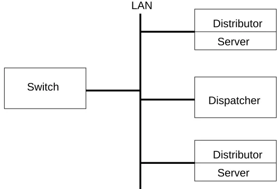
Scalable LARD
The standard cluster architecture of the proposed LARD implementation uses a
cen-tralised dispatcher or front-end switch and the TCP hand-off technique. TCP hand-off
is indeed more scalable than other TCP gatewaying designs such as TCP splicing, but
empirical experiments have shown that peak throughput of TCP hand-off is limited to
about 3500 connections per second with real trace workloads and doesn’t scale well
be-yond four cluster nodes [4].
The centralised nature of the content-aware request distribution strategies (e.g. LARD) makes it difficult to obtain scalability by using multiple front-end switches, which
fur-thermore would introduce load-balancing concerns. The approach taken [4] separates the
functionality of the front-end node in two components, a distributor and a dispatcher, as
shown by figure 2.12. The dispatcher is in charge of deciding which backend server will
handle each request, while the distributor is the component that actually performs the
action of passing or “handing off” the request to the server. With this division, it can
be appreciated that while the dispatcher needs to be centralised to be able to implement
Server
Server
Server LAN
[image:24.595.156.438.78.267.2]Distributor Dispatcher
Figure 2.12: Centralised dispatcher and distributor
independent of any centralised control, while still being able to keep a centralised
content-aware dispatcher as shown in figure 2.13.
Server Distributor
Server Distributor LAN
Switch
Dispatcher
Figure 2.13: Scalable LARD cluster architecture
To be able to use distributed distributors, this architecture uses a fast layer 4 switch
that is the single point of contacts for clients, working the same way as other Layer 4
cluster architectures. The main difference is that once the requests hit the distributors, the
dispatcher will be contacted and the distributor that received the request will hand off the request to the backend server that the dispatcher considers adequate. As the switch does
not perform any content-aware distribution, the benefit is that it can be a fast
hardware-based implementation.
The proposed approach is considerably more scalable than using a single front-end
node that performs content-aware request distribution based on LARD or other algorithm.
[image:24.595.158.435.362.550.2]the bottleneck in this kind of switches, and making it distributed better scalability can
be achieved paying only a small latency penalty. The centralised dispatcher could be a
potential bottleneck as well, but it is not in practice as it is a very simple component that
can be implemented in a dedicated node and handle up to 50,000 connections per second
[4].
2.3.5
WARD
Workload-Aware Request Distribution (WARD) is a content-aware request distribution
strategy that intends to improve some shortcomings of the scalable LARD architecture.
The basic idea behind WARD is that “by mapping a small set of most frequent files to
be served by multiple number of nodes, we can improve both locality of accesses and the
cluster performance significantly” [39].
In a cluster using LARD of n nodes, only 1/n of the requests will be handled locally
forwarding the other (n-1)/n requests, a relatively expensive operation [4] that can
in-troduce a forwarding overhead that limits the performance and scalability of the cluster.
Additionally, Web server workload studies have shown that 90% of the web requests are
for only 2-10% of all the accessed documents, constituting less than 5% of the total work-ing set. WARD aims to minimise forwardwork-ing overhead from handlwork-ing the most frequent
files while keeping the benefits of the optimised use of the overall cluster main memory
caches that LARD provides.
WARD chooses a set of most frequently accessed documents, called core, that will be
served by all the cluster nodes and partitions the rest of the files to be served by the
back-end servers.It uses an algorithm called ward-analysis [39] that identifies the optimal core
for a given workload and system parameters such as the number of nodes, main memory
cache size, TCP hand-off overheard and disk access overhead. The core is proposed to be computed once in a day, so that the cluster will always use the values obtained from
previous day’s workload.
This basic form of WARD is very similar to the scalable LARD architecture, and
it would use the LARD distribution algorithm for the files that are not in the core. The
other change proposed in WARD is to decentralise the dispatcher, by using a precomputed
partitioning of the working set based on the workload of the previous days. The scalable
LARD architecture introduces the idea of a co-located distributor that resides in every
backend server, but still keeps a centralised dispatcher that every node has to contact to
decide which backend server will handle the request. With a decentralised dispatcher,
the overhead of a unique dispatcher is eliminated and better scalability is achieved. This approach will work well assuming that the core is reasonably stable, if workload stability
is not possible, the simpler “dynamic” centralised dispatcher will be a better solution most
Simulation tests [39] show that WARD provides performance improvements of up to
260% increased throughput compared to round-robin strategies and up to 50% compared
to locality-based strategies such as LARD. The use of a distributed dispatcher together
with previous day’s workload information improves throughput furthermore for typical
stable workloads.
2.3.6
PPBL
Most web cluster architectures use a push approach to request distribution, the dispatcher
decides which backend server should handle a given request based on layer 3, 4 or 7
information and then sends or “pushes” the request to the chosen server. WARD [39]
in-troduces a distributed dispatcher, but it does so at the expense of having a static
dispatch-ing information that is updated with previous day’s information instead of more dynamic
algorithms like LARD [17]. The PPBL prototype web proxy uses a Distributed Shared
Memory (DSM) based cluster interconnected by a Scalable Coherent Interface (SCI)
net-work. It uses certain features of the DSM architecture to obtain better performance, and it
is uncertain if this design would be able to be generalised to be appropriate for non-DSM
clusters.
Parallel Pull-Based LRU [26] is an architecture that aims to distribute the dispatcher
while still having the advantages of a dynamic content-based request distribution
algo-rithm. As its name implies, it uses a “pull” approach to request distribution, where
backend server nodes don’t just receive requests but take part in a parallelised request
distribution algorithm. This algorithm uses the basic idea that the backend servers, pull
the requests that they should handle from an incoming request queue that resides in the
front-end node.
The algorithm works as follows: each backend node selects a pending URL from the incoming queue and checks if it is in its own URL list. If the matching entry is found, the
backend modifies the incoming queue to signal that it is handling the request and sends
the reply directly to the client. The front-end can delete the entry from the incoming
queue once a backend node has decided to handle it. If the entry is not found by any of
the backend servers, the front-end will choose the less loaded node to handle it. The load
information is kept in the DSM and periodically updated by each backend. If the backend
that has found the request in its local URL list is overloaded, it can choose a less loaded in
the entry’s server list or if there is none, it can forward it directly to the less loaded node in
the cluster keeping all the information about the URL local, accessible to the other node
through the DSM.
A first implementation that used the above design proved not to be very scalable.
Throughput doesn’t improve anywhere near linearly by adding nodes to the cluster, and
from performing better. A second implementation is proposed by the authors that will
limit the number of locks that are necessary for each request. This implementation uses
new data structures and an special SCI mapping that performs a fast atomic fetch and
increment on each access that can be used by the backend nodes to signal when they have
finished evaluating if a given request is for them. Good scalability is achieved by making
use of these low level capabilities of the middleware, a cluster of 7 nodes has a 580%
better throughput than a single node server.
PPBL is a very interesting design that takes a new approach to request distribution,
both because it uses a pull based approach whereas most other cluster architectures use
a push design as well as because it makes use of high-speed SCI networks and DSM
middleware to achieve better scalability. It would be interesting to evaluate if the ideas
behind PPBL are applicable outside of the specific implementation technologies used
by the authors, as they had to resort to low-level optimisations to achieve reasonable
scalability.
2.4
Web caching replacement policies
Web caching used with HTTP proxy servers is a widely used and well studied [3, 8, 7, 27,
28] mechanism for reducing both latency and network traffic in accessing resources on the
Web. In the context of a Web server, the purpose of a cache and its associated replacement
policy is to maximise the number of requests that are handled with data available in the
main memory of the server, avoiding thus costly file-system input-output operations.
Modern computer main memory and high speed networks feature access speeds which
are still considerably faster than the speeds of magnetic hard disks, making the
manage-ment of an in-memory cache an important and frequently overlooked part of the design of a clustered web server. Web server cluster designers, both research-oriented and
commer-cial, acknowledge the benefits of taking in account locality of references in Web traffic
for added performance, but the majority of proposed solutions deal with this issue only
at the request distribution level. Unlike with Web proxies, there is little previous research
on cooperative caching strategies for Web clusters.
The main aspect that determines the performance of a cache is its cache replacement
policy. This algorithm will be in charge of deciding which document(s) is/are evicted
from the cache when its capacity has reached its limits and a new document has to be
loaded and maybe cached by the server. Before the Web, cache replacement policies
have been studied for file-system caching and virtual memory page replacement, but Web caching has different requirements than those domains, most importantly that Web objects
(HTML pages, image files, etc.) vary widely in size. Furthermore, Web cluster caches
the nodes are normally interconnected using high-speed private networks, so for a given
node it is always preferable to obtain a resource from the main memory of another node
instead of reading it from the file-system.
When evaluating Web proxy cache replacement policies several performance metrics
are commonly considered:
Hit rate The fraction of the total requests that are served from the local cache.
Byte hit rate The percentage of network traffic that were sent directly from the cache,
without involving file-system operations.
Optimising one of these two metrics doesn’t optimise the other, so a trade-off has to me
made, depending if CPU cycles or network bandwidth is the bottleneck. Byte hit rate is important for Web proxies that need to minimise the traffic between the proxy and
the original servers. In a common deployment scenario of a Web proxy such as in a
University campus, there are important costs in latency and/or money for each byte part
of a request that requires a connection to the original server, while Web clusters do not
have this concern, as the nodes in a cluster use high-speed interconnects. Thus, the most
important metric when evaluating cache replacement policies for Web clusters is hit rate.
2.4.1
Least Recently Used (LRU)
Least Recently is a very popular policy in file system and virtual memory caching, it evicts the document which has been least recently accessed from the cache. In the absence of
cost and size concerns, LRU is the optimal on-line algorithm for requests sets with good
locality. However in Web caches, replacing a recently used big file can give better hit ratio
than replacing a less recently used but small file. Thus, for a good Web cache replacement
policy size has to be taken into consideration and the basic LRU is not a good option
because it ignores the sizes of cached documents.
There are several variations of LRU that try to improve its performance:
LRU Size
[3] It is a variant of LRU [3] that tries to minimize the number of documents replaced by
taking the size of them in account as well as the last access time. It will always remove
the larger documents first, and fall back to LRU in the case of having several documents
of the same size.
Log(Size)+LRU [3]
This variation of LRU-Size uses a logarithm of the size, to avoid giving to much weight
the case of LRU-Size.
LRU-Min
This policy [3] gets a list of documents that are of bigger size than the requested document,
and evict them in LRU order until there is enough free space on the cache to fit the new
request. When there are no files bigger than the requested document left in the cache,
LRU is used to choose the next eviction candidate(s).
LRU-Threshold
Another variant of LRU that will avoid caching documents that are too big by setting a
threshold size so that no document larger than that size will be cached [3].
Segmented LRU
Segmented LRU is a frequency-based variation of LRU designed for fixed-size page
caching in file-systems. Observing that objects with two accesses are much more popular
than those with only one access, the cache space is partitioned into two LRU segments:
probationary segment and protected segment.
Objects brought to the cache are initially put in the probationary segment, and will
only be moved to the protected segment if they get at least one more access.When an
object has to be evicted, it will be taken from the probationary segment first. The protected segment has a fixed size, and when it gets full the objects that don’t have space in it will
be kept in the probationary segment.
Segmented LRU is not suitable for Web caching as it ignores the size of cached objects
and assumes fixed-size objects. Furthermore, it has the problem of needing
parametrisa-tion of the number and sizes of segments.
2.4.2
Least Frequently Used (LFU)
This policy keeps track of the number of requests that are made for each document in the cache, evicting the document of documents that have been less frequently requested first
if space is needed. As it ignores the document sizes, it can lead to an inefficient use of
the space on the cache. Where LRU is equivalent to sorting by last access time, LFU is
equivalent to sorting by number of accesses.
2.4.3
Hyper-G
It is a policy that combines LFU, LRU and the size aspect [28]. It uses a hierarchical
there is still more than one candidate the size of the documents is taken in account for
deciding which one to evict.
2.4.4
Pitkow-Recker
It uses a different primary key depending whether or not all cached documents have been
accessed in the current day [28]. It will use the LRU policy, except if all the documents
have been accessed today, in which case it uses a Size removal policy, removing the largest one(s).
2.4.5
Hybrid
The Hybrid policy [27] has been designed to minimise the time that end-users wait for
a page to load as well as hit rate and byte hit rate. It is a hybrid of several factors,
considering download time, number of request (frequency) and size. Hybrid selects for
eviction the document i with the lowest value for the following expression:
(clatseri +WB/cbwseri)(nrefi**WN)/Si
where nrefi is the number of references to document i since it last entered the cache, si is the size in bytes of document i, and WB and WN are constants that set the relative im-portance of the variables cbwseri and nrefi, respectively. A document won’t be evicted if the expression above evaluates to a large value, which could occur if the document is in
a server that takes a long time to connect and is connected via a low bandwidth link, if the
document has been referenced many times in the past and if the document size is small.
Although this replacement policy has the advantage of considering the latency of a
document, this is only applicable to Web proxy caching. Retrieval latency is not a concern
on Web server clusters, as all the nodes are expected to be interconnected by the same kind of network and the latency should be the same for all of them.
2.4.6
Lowest Relative Value (LRV)
LRV is based on the relative value (V), a function of the probability that a document is
accessed again (Pr). The LRV algorithm simply selects the document with the Lowest Relative Value as the candidate for eviction. As V is proportional to Pr, the issue is to find this probability.
The parameters used for computing Pr are the following:
Time from the last access.
Number of previous accesses.
In the simulations carried out by Rizzo and Vicisano [19] LRV features higher byte hit
rate than other policies in all conditions, and has better hit rate than all of them except
SIZE.
2.4.7
GreedyDual-Size
GreedyDual-Size is a variation of GreedyDual, an algorithm for uniform-size
variable-cost cache replacement [12]. GreedyDual deals with the case in which cached pages are of the same size but have different associated costs for bringing them into the cache. It
associates a H value with each cached page, initially set to the cost of adding a page from
secondary storage to the cache. When a replacement has to be made, the page with the
lowest H is evicted, and all the rest pages reduce their H value by the evicted page’s H
value.
GreedyDual-Size incorporates the size factor by setting the initial H value of a
docu-ment to cost/size, where cost is the cost of bringing the docudocu-ment to the cache and size is
the size of the document in bytes. There are different versions of GreedyDual-Size that
differ on the definition of cost, depending if the goal of the replacement algorithm is to
maximise hit rate or byte hit rate. GreedyDual-Size(1) sets the cost to 1 and achieves the best hit rate while GreedyDual-Size(packets), which sets the cost to 2+size/536 (the
esti-mated number of network packets sent and received if a cache miss happens) maximises
byte hit ratio. GreedyDual-Size(1) has very good hit rate at the price of lower byte hit
rate, while GreedyDual-Size(packet) achieves the highest byte hit rate with moderately
lower hit rate than GreedyDual-Size(1).
Although GreedyDual-Size(packets) would be the recommended policy for the overall
best performance in Web proxy caches, in the case of a Web cluster GreedyDual-Size(1)
would be more appropriate as it achieves better hit rate by not paying attention to the byte hit rate. This replacement policy can be considered the current “champion” of web cache
Chapter 3
Design and implementation
Web clusters have been traditionally implemented by “growing” single-node Web server
architectures instead of being designed from scratch as a system that takes advantages
of a clustering architecture, clustering has been more “bolt-on” Web servers than
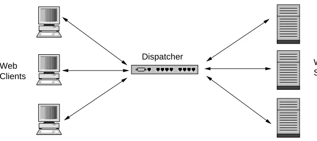
“built-in”. This legacy reflects on the design of commercial Web clustering and load balancing solutions. A very common deployment scenario for a commercial clustered Web server
configuration is shown in Figure 3.1, where the dispatcher is the central point of contact
for all the clients and it distributes requests to the backend Web servers using layer 4
switching with either layer 2 or 3 forwarding. There are some advantages to this design:
Backend nodes are standard Web servers, keeping the same configuration and
ad-ministration needs of a single-node Web server, minimising the system
administra-tion overhead of moving from a single Web server to a cluster.
The front-end dispatcher can be a dedicated device with embedded software that is
very efficient at the request distribution and load balancing tasks it performs.
Every component in the cluster is transparent of the others, it is a loosely-coupled
architecture where each component has no or minimal knowledge of how the others work, providing both fault tolerance and simpler administration and deployment, as
well as allowing heterogeneous systems to work together.
The architecture in Figure 3.1 is simple and provides some degree of scalability.
How-ever, goals of higher scalability and better use of resources available on the backend nodes
require different solutions. Most of the commercial state-of-the-art Web switch/dispatcher products have the optional functionality of taking in account application layer (OSI layer
7) information, such as the requested URL or the current session.
Application layer data awareness (layer 7 switching) is important for achieving better
request distribution , but commercial dispatchers pay a big performance price when doing
Web Servers Dispatcher
[image:33.595.128.439.75.214.2]Web Clients
Figure 3.1: Common Web cluster deployment scenario.
The fact that these clustering solutions are highly transparent between their own compo-nents (dispatchers and backend nodes) as well as to the outside world (Web browsers)
makes it difficult to implement highly scalable clustered Web servers with them.
In this section the design and implementation of a clustered Web server that uses
com-modity off-the-shelf (COTS) hardware and distributed software components is described.
Designing all the components from scratch allows more flexibility for using
state-of-the-art algorithms and controlling resources globally in the cluster, achieving better
load-balancing and efficiency, which should lead to good scalability. This Web cluster could
be considered as a Web server with an integrated content-aware layer 7 switch and global
cache management.
All the clustering software discussed in this dissertation has been implemented in Java. It is not very common in the research literature to use Java as the platform for
implementing prototype Web servers or proxies. However, there are popular commercial
application server products implemented in Java that prove that it is a viable platform
for high-performance network servers. Furthermore, with the release of Java Standard
Edition version 1.4, non-blocking I/O support is made available to Java developers both
under Unix as well as Win32 operating systems.
This chapter is organised as follows: first the overall architecture of the clustered Web
server is described; next each of the components’ (front-end/dispatcher, node manager
and cache manager) design is discussed, giving details of their different implementation approaches and how they interact with the rest of the cluster components.
3.1
Architecture
Three main components form the clustered Web server discussed in this dissertation:
Front-end The front-end is the process that will be the single point of contact for all
the clients that want to issue an HTTP request to the server and receive a response
Response Request
Node Manager 2
Dispatcher Cache Manager
Node Manager 1
[image:34.595.94.512.78.233.2]Cluster
Figure 3.2: Logical view of the components in a running cluster.
so it is the most performance-sensitive component of the server. It has three main
responsibilities:
1. Wait for connections on a TCP port and accept requests from Web clients,
keeping track of the open client connections.
2. Obtain the request URLs and decide which backend node will handle them.
3. Receive and send back the responses generated by the backend nodes to the
appropriate clients.
Cache manager The cache manager is the component that holds cluster-wide global
in-formation about the state of the backend nodes’ main memory cache. Its main
responsibility is to keep a mapping of files and the nodes that have them them in
their cache, so that when a backend node has a request for a file that is not in its local cache it can retrieve it directly from another node’s main memory instead of
accessing the file-system. The reason for this design is that with the current
net-work interconnection technologies it should be faster for a node to retrieve some
data from another node’s main memory across the network than reading it from the
file-system.
Node manager The node manager is the main “worker” process in the cluster. Each
backend node runs one or more node manager process. Its main responsibilities
are:
1. Retrieve requests assigned to it by the front-end, obtain the response data and
send it back to the front-end.
2. Keep a local main memory cache of files, with its associated cache
There are two possible views that can be used when describing how these components
(or instances of them) are organised in a running clustered Web server to handle client
requests. Figure 3.2 shows a logical view where one front-end, two node managers and
one cache manager work to accept a request, route it through the cluster software and
send the right response back to the client.
Figure 3.3 describes the same cluster configuration as Figure 3.2 but from a
physi-cal point view, showing how the component processes could be distributed in different computers. In this case there is one system dedicated as front-end, another one running
the cache manager process and two nodes running one node manager process each. This
configuration is the one that will be evaluated in this dissertation, with the only difference
of the number of systems running node manager processes.
The server software is flexible with respect to the physical distribution of its
compo-nents. It requires the existence of one front-end, one cache manager and one or more node
manager, but does not require them to be physically distributed among the nodes of the
cluster in a certain way. It is possible for example to have all the components running in
the same system, even though that would obviously not be recommended.
Another aspect in which the cluster software offers high flexibility is that different implementations of its subsystems can be used by specifying a command line option at
startup time. For example, there are multi-threaded and non-blocking I/O
implementa-tions of the front-end server, and there are different request distribution and cache
re-placement policies available as well. It is a framework that can easily integrate new
im-Response Request
Cluster Dispatcher
Node Manager 1
Cache Manager
[image:35.595.87.510.468.621.2]Node Manager 2
Figure 3.3: Physical view of the components in a running cluster.
3.2
Inter-process communication
The Web cluster software described in this dissertation is designed to run in a cluster of
computers connected by a network that supports TCP/IP. Thus, there is a need to define a
set of protocols that the different components - front-end, cache manager and node man-agers - will use for communicating between them. For example, each node manager needs
to have a protocol that allows it to contact the front-end and retrieve HTTP requests that
the front-end has assigned to it. In the same way, there has to be an agreed-upon protocol
between node managers and the cache manager so that they can collaborate to implement
an effective caching policy that takes advantage of the aggregated main memory cache
available in the cluster.
Two alternative inter-process communication protocols have been implemented in the
cluster, the first one uses Java interfaces via Java Remote Method Invocation (RMI) and the other one uses a custom application-specific protocol based on low-level TCP socket
connections. These two protocols will be described in the following sections.
3.2.1
RMI protocol
Remote Method Invocation (RMI) is a Java-specific middleware for implementing
dis-tributed object systems. It allows Java programs residing in different address spaces and
potentially different machines to invoke object method calls between themselves. RMI
makes it possible to ignore up to a certain extent that the object that will receive a given
method call can possibly be in a different machine across the network.
The main advantages of RMI are that it is a standard part of the Java platform and that it makes it very simple to specify inter-process communication protocols using Java
interfaces. RMI servers are simply objects that implement a certain remote interface and
“export” it to the RMI subsystem, making those objects accessible by their interfaces to
remote Java processes.
However, as will be later discussed, RMI has shown to not be suitable for
implement-ing high-performance scalable servers. It uses a thread and an associated TCP connection
for each method call, an approach with very poor scalability. Threads and TCP
connec-tions are expensive resources with high overhead, so the standard RMI implementation is not suitable for systems that are expected to handle hundreds or even thousands of method
calls per second. Even if Java has introduced new much more scalable non-blocking I/O
in 1.4 the rest of the APIs that come with the Java Development Kit (JDK), RMI included,
do not use it. A reimplementation of RMI using non-blocking I/O and multiplexed TCP
connections would possibly be more scalable, BEA WebLogic uses a proprietary