WELDING
METALLURGY
SECOND EDITION
Sindo Kou
Professor and ChairDepartment of Materials Science and Engineering University of Wisconsin
Published by John Wiley & Sons, Inc., Hoboken, New Jersey. Published simultaneously in Canada.
No part of this publication may be reproduced, stored in a retrieval system, or transmitted in any form or by any means, electronic, mechanical, photocopying, recording, scanning, or otherwise, except as permitted under Section 107 or 108 of the 1976 United States Copyright Act, without either the prior written permission of the Publisher, or authorization through payment of the appropriate per-copy fee to the Copyright Clearance Center, Inc., 222 Rosewood Drive, Danvers, MA 01923, 978-750-8400, fax 978-750-4470, or on the web at www.copyright.com. Requests to the Publisher for permission should be addressed to the Permissions Department, John Wiley & Sons, Inc., 111 River Street, Hoboken, NJ 07030, (201) 748-6011, fax (201) 748-6008, e-mail: permreq@wiley.com.
Limit of Liability/Disclaimer of Warranty: While the publisher and author have used their best efforts in preparing this book, they make no representations or warranties with respect to the accuracy or completeness of the contents of this book and specifically disclaim any implied warranties of merchantability or fitness for a particular purpose. No warranty may be created or extended by sales representatives or written sales materials. The advice and strategies contained herein may not be suitable for your situation. You should consult with a professional where appropriate. Neither the publisher nor author shall be liable for any loss of profit or any other commercial damages, including but not limited to special, incidental, consequential, or other damages.
For general information on our other products and services please contact our Customer Care Department within the U.S. at 877-762-2974, outside the U.S. at 3993 or fax 317-572-4002.
Wiley also publishes its books in a variety of electronic formats. Some content that appears in print, however, may not be available in electronic format.
Library of Congress Cataloging-in-Publication Data Kou, Sindo.
Welding metallurgy / Sindo Kou.–2nd ed. p. cm.
“A Wiley-Interscience publication.”
Includes bibliographical references and index. ISBN 0-471-43491-4
1. Welding. 2. Metallurgy. 3. Alloys. I. Title. TS227 .K649 2002
671.5¢2–dc21
2002014327
Printed in the United States of America.
CONTENTS
Preface xiii
I INTRODUCTION 1
1 Fusion Welding Processes 3
1.1 Overview 3
1.2 Oxyacetylene Welding 7
1.3 Shielded Metal Arc Welding 11
1.4 Gas–Tungsten Arc Welding 13
1.5 Plasma Arc Welding 16
1.6 Gas–Metal Arc Welding 19
1.7 Flux-Core Arc Welding 22
1.8 Submerged Arc Welding 22
1.9 Electroslag Welding 24
1.10 Electron Beam Welding 27
1.11 Laser Beam Welding 29
References 33
Further Reading 34
Problems 34
2 Heat Flow in Welding 37
2.1 Heat Source 37
2.2 Analysis of Heat Flow in Welding 47
2.3 Effect of Welding Parameters 53
2.4 Weld Thermal Simulator 58
References 60
Further Reading 62
Problems 62
3 Chemical Reactions in Welding 65
3.1 Overview 65
3.2 Gas–Metal Reactions 68
3.3 Slag–Metal Reactions 82
References 92
Further Reading 95
Problems 95
4 Fluid Flow and Metal Evaporation in Welding 97
4.1 Fluid Flow in Arcs 97
4.2 Fluid Flow in Weld Pools 103
4.3 Metal Evaporation 114
4.4 Active Flux GTAW 116
References 117
Further Reading 119
Problems 120
5 Residual Stresses, Distortion, and Fatigue 122
5.1 Residual Stresses 122
5.2 Distortion 126
5.3 Fatigue 131
5.4 Case Studies 137
References 140
Further Reading 141
Problems 141
II THE FUSION ZONE 143
6 Basic Solidification Concepts 145
6.1 Solute Redistribution during Solidification 145
6.2 Solidification Modes and Constitutional Supercooling 155
6.3 Microsegregation and Banding 160
6.4 Effect of Cooling Rate 163 6.5 Solidification Path 166
References 167
Further Reading 168
Problems 169
7 Weld Metal Solidification I: Grain Structure 170
7.1 Epitaxial Growth at Fusion Boundary 170
7.2 Nonepitaxial Growth at Fusion Boundary 172
7.3 Competitive Growth in Bulk Fusion Zone 174
7.4 Effect of Welding Parameters on Grain Structure 174
7.5 Weld Metal Nucleation Mechanisms 178
References 195 Further Reading 197
Problems 197
8 Weld Metal Solidification II: Microstructure within Grains 199
8.1 Solidification Modes 199
8.2 Dendrite and Cell Spacing 204
8.3 Effect of Welding Parameters 206
8.4 Refining Microstructure within Grains 209
References 213
Further Reading 213
Problems 214
9 Post-Solidification Phase Transformations 216
9.1 Ferrite-to-Austenite Transformation in Austenitic Stainless Steel Welds 216
9.2 Austenite-to-Ferrite Transformation in Low-Carbon, Low-Alloy Steel Welds 232
References 239
Further Reading 241
Problems 241
10 Weld Metal Chemical Inhomogeneities 243
10.1 Microsegregation 243
10.2 Banding 249
10.3 Inclusions and Gas Porosity 250
10.4 Inhomogeneities Near Fusion Boundary 252
10.5 Macrosegregation in Bulk Weld Metal 255
References 260
Further Reading 261
Problems 261
11 Weld Metal Solidification Cracking 263
11.1 Characteristics, Cause, and Testing 263 11.2 Metallurgical Factors 268
11.3 Mechanical Factors 284
11.4 Reducing Solidification Cracking 285
11.5 Case Study: Failure of a Large Exhaust Fan 295
References 296
Further Reading 299
III THE PARTIALLY MELTED ZONE 301
12 Formation of the Partially Melted Zone 303
12.1 Evidence of Liquation 303
12.2 Liquation Mechanisms 304
12.3 Directional Solidification of Liquated Material 314
12.4 Grain Boundary Segregation 314
12.5 Grain Boundary Solidification Modes 316 12.6 Partially Melted Zone in Cast Irons 318
References 318
Problems 319
13 Difficulties Associated with the Partially Melted Zone 321
13.1 Liquation Cracking 321
13.2 Loss of Strength and Ductility 328
13.3 Hydrogen Cracking 328
13.4 Remedies 330
References 336
Problems 338
IV THE HEAT-AFFECTED ZONE 341
14 Work-Hardened Materials 343
14.1 Background 343
14.2 Recrystallization and Grain Growth in Welding 347 14.3 Effect of Welding Parameters and Process 349
References 351
Further Reading 352
Problems 352
15 Precipitation-Hardening Materials I: Aluminum Alloys 353
15.1 Background 353
15.2 Al–Cu–Mg and Al–Mg–Si Alloys 359
15.3 Al–Zn–Mg Alloys 367
15.4 Friction Stir Welding of Aluminum Alloys 370
References 371
Further Reading 372
Problems 372
16 Precipitation-Hardening Materials II: Nickel-Base Alloys 375
16.2 Reversion of Precipitate and Loss of Strength 379
16.3 Postweld Heat Treatment Cracking 384
References 390
Further Reading 392
Problems 392
17 Transformation-Hardening Materials: Carbon and
Alloy Steels 393
17.1 Phase Diagram and CCT Diagrams 393
17.2 Carbon Steels 396
17.3 Low-Alloy Steels 404
17.4 Hydrogen Cracking 410
17.5 Reheat Cracking 418
17.6 Lamellar Tearing 422
17.7 Case Studies 425
References 427
Further Reading 429
Problems 430
18 Corrosion-Resistant Materials: Stainless Steels 431
18.1 Classification of Stainless Steels 431 18.2 Austenitic Stainless Steels 433 18.3 Ferritic Stainless Steels 446 18.4 Martensitic Stainless Steels 449 18.5 Case Study: Failure of a Pipe 451
References 452
Further Reading 453
Problems 454
PREFACE
Since the publication of the first edition of this book in 1987, there has been much new progress made in welding metallurgy. The purpose for the second edition is to update and improve the first edition. Examples of improvements include (1) much sharper photomicrographs and line drawings; (2) integration of the phase diagram, thermal cycles, and kinetics with the microstructure to explain microstructural development and defect formation in welds; and (3) additional exercise problems. Specific revisions are as follows.
In Chapter 1 the illustrations for all welding processes have been re-drawn to show both the overall process and the welding area. In Chapter 2 the heat source efficiency has been updated and the melting efficiency added. Chapter 3 has been revised extensively, with the dissolution of atomic nitrogen, oxygen, and hydrogen in the molten metal considered and electrochemical reactions added. Chapter 4 has also been revised extensively, with the arc added, and with flow visualization, arc plasma dragging, and turbulence included in weld pool convection. Shot peening is added to Chapter 5.
Chapter 6 has been revised extensively, with solute redistribution and microsegregation expanded and the solidification path added. Chapter 7 now includes nonepitaxial growth at the fusion boundary and formation of non-dendritic equiaxed grains. In Chapter 8 solidification modes are explained with more illustrations. Chapter 9 has been expanded significantly to add ferrite formation mechanisms, new ferrite prediction methods, the effect of cooling rate, and factors affecting the austenite–ferrite transformation. Chapter 10 now includes the effect of both solid-state diffusion and dendrite tip under-cooling on microsegregation. Chapter 11 has been revised extensively to include the effect of eutectic reactions, liquid distribution, and ductility of the solidifying metal on solidification cracking and the calculation of fraction of liquid in multicomponent alloys.
Chapter 12 has been rewritten completely to include six different liquation mechanisms in the partially melted zone (PMZ), the direction and modes of grain boundary (GB) solidification, and the resultant GB segregation. Chapter 13 has been revised extensively to include the mechanism of PMZ cracking and the effect of the weld-metal composition on cracking.
Chapter 15 now includes the heat-affected zone (HAZ) in aluminum– lithium–copper welds and friction stir welds and Chapter 16 the HAZ of Inconel 718. Chapter 17 now includes the effect of multiple-pass welding on
reheat cracking and Chapter 18 the grain boundary chromium depletion in a sensitized austenitic stainless steel.
The author thanks the National Science Foundation and NASA for supporting his welding research, from which this book draws frequently. He also thanks the American Welding Society and ASM International for per-missions to use numerous copyrighted materials. Finally, he thanks C. Huang, G. Cao, C. Limmaneevichitr, H. D. Lu, K. W. Keehn, and T. Tantanawat for pro-viding technical material, requesting permissions, and proofreading.
Sindo Kou
PART I
Introduction
1
Fusion Welding Processes
Fusion welding processes will be described in this chapter, including gas welding, arc welding, and high-energy beam welding. The advantages and dis-advantages of each process will be discussed.
1.1 OVERVIEW
1.1.1 Fusion Welding Processes
Fusion welding is a joining process that uses fusion of the base metal to make the weld. The three major types of fusion welding processes are as follows:
1. Gas welding:
Oxyacetylene welding (OAW) 2. Arc welding:
Shielded metal arc welding (SMAW) Gas–tungsten arc welding (GTAW) Plasma arc welding (PAW)
Gas–metal arc welding (GMAW) Flux-cored arc welding (FCAW) Submerged arc welding (SAW) Electroslag welding (ESW) 3. High-energy beam welding:
Electron beam welding (EBW) Laser beam welding (LBW)
Since there is no arc involved in the electroslag welding process, it is not exactly an arc welding process. For convenience of discussion, it is grouped with arc welding processes.
1.1.2 Power Density of Heat Source
Consider directing a 1.5-kW hair drier very closely to a 304 stainless steel sheet 1.6 mm (1/
50 mm (2 in.) diameter, and the sheet just heats up gradually but will not melt. With GTAW at 1.5 kW, however, the arc concentrates on a small area of about 6 mm (1/
4in.) diameter and can easily produce a weld pool. This example clearly
demonstrates the importance of the power density of the heat source in welding.
The heat sources for the gas, arc, and high-energy beam welding processes are a gas flame, an electric arc, and a high-energy beam, respectively. The power density increases from a gas flame to an electric arc and a high-energy beam. As shown in Figure 1.1, as the power density of the heat source increases, the heat input to the workpiece that is required for welding decreases. The portion of the workpiece material exposed to a gas flame heats up so slowly that, before any melting occurs, a large amount of heat is already conducted away into the bulk of the workpiece. Excessive heating can cause damage to the workpiece, including weakening and distortion. On the con-trary, the same material exposed to a sharply focused electron or laser beam can melt or even vaporize to form a deep keyhole instantaneously, and before much heat is conducted away into the bulk of the workpiece, welding is com-pleted (1).
Therefore, the advantages of increasing the power density of the heat source are deeper weld penetration, higher welding speeds, and better weld quality with less damage to the workpiece, as indicated in Figure 1.1. Figure 1.2 shows that the weld strength (of aluminum alloys) increases as the heat input per unit length of the weld per unit thickness of the workpiece decreases (2). Figure 1.3ashows that angular distortion is much smaller in EBW than in
Increasing damage to workpiece
Increasing penetration, welding speed, weld quality, equipment cost
Power density of heat source high energy beam welding arc
welding gas
welding
Heat input to
wo
rkpiece
GTAW (2). Unfortunately, as shown in Figure 1.3b, the costs of laser and elec-tron beam welding machines are very high (2).
1.1.3 Welding Processes and Materials
Table 1.1 summarizes the fusion welding processes recommended for carbon steels, low-alloy steels, stainless steels, cast irons, nickel-base alloys, and
50
40
30
5 10 50 100 500 Heat input, kJ/in./in.
[image:15.441.136.307.68.232.2]Strength, ksi 7039 5083 60 2219 6061
Figure 1.2 Variation of weld strength with heat input per unit length of weld per unit thickness of workpiece. Reprinted from Mendez and Eagar (2).
Productivity, cm/s Flame Arc Laser electron beam Productivity, inch of weld/s
Capital equipment, dollars
Po w er density , W/m 2
0.1 1 10 100
0.04 0.4 4 40 400
103 105 107 103 105 107 (b) t EBW GT AW
Weld thickness t, mm
0 20 40
Distor tion angle deg ree 2 4 6 8 0 (a) α α
T ABLE 1.1 Ov ervie w of W elding Processes a Material T hickness b SMA W SA W GMA W FC A W GT A W P A W ESW OFW EBW LBW Carbon S ✕✕ ✕ ✕ ✕ ✕ steels I ✕✕ ✕ ✕ ✕ ✕ ✕ M ✕✕ ✕ ✕ ✕ ✕ T ✕✕ ✕ ✕ ✕ ✕ ✕ Low-alloy S ✕✕ ✕ ✕ ✕ ✕ steels I ✕✕ ✕ ✕ ✕ ✕ M ✕✕ ✕ ✕ ✕ T ✕✕ ✕ ✕ ✕ ✕ Stainless S ✕✕ ✕ ✕✕ ✕ ✕ steels I ✕✕ ✕ ✕ ✕✕ ✕ M ✕✕ ✕ ✕ ✕ ✕ T ✕✕ ✕ ✕ ✕ ✕ Cast iron I ✕ ✕ M ✕✕ ✕ ✕ ✕ T ✕✕ ✕ ✕ ✕ Nickel S ✕✕ ✕ ✕ ✕ ✕ and alloys I ✕✕ ✕ ✕✕ ✕ M ✕✕ ✕ ✕ ✕ T ✕✕ ✕ ✕ Aluminum S ✕✕ ✕ ✕ ✕ and alloys I ✕✕ ✕ M ✕✕ ✕ T ✕✕ a Process code: SMA W ,
shielded metal arc welding;
SA
W
,
submerged arc welding;
GMA
W
,
gas–metal arc welding;
FC
A
W
,
flux-cored arc welding;
GT
gas–tungsten arc welding;
P
A
W
,
plasma arc welding;
ESW
,
electroslag welding;
OFW
,
oxyfuel gas welding;
EBW
,
electron beam welding;
LBW , laser beam welding . b Abbreviations: S , sheet,
up to 3
mm (
1/8
in.); I, intermediate , 3–6 mm (
1/8
–
1/4
in.);
M,
medium,
6–19
mm (
1/4
–
3/4
in.); T , thick, 19 mm (
3/4
in.) and up;
aluminum alloys (3). For one example, GMAW can be used for all the materi-als of almost all thickness ranges while GTAW is mostly for thinner workpieces. For another example, any arc welding process that requires the use of a flux, such as SMAW, SAW, FCAW, and ESW, is not applicable to aluminum alloys.
1.1.4 Types of Joints and Welding Positions
Figure 1.4 shows the basic weld joint designs in fusion welding: the butt, lap, T-, edge, and corner joints. Figure 1.5 shows the transverse cross section of some typical weld joint variations. The surface of the weld is called the face, the two junctions between the face and the workpiece surface are called the toes, and the portion of the weld beyond the workpiece surface is called the reinforcement. Figure 1.6 shows four welding positions.
1.2 OXYACETYLENE WELDING
1.2.1 The Process
Gas welding is a welding process that melts and joins metals by heating them with a flame caused by the reaction between a fuel gas and oxygen. Oxy-acetylene welding (OAW), shown in Figure 1.7, is the most commonly used gas welding process because of its high flame temperature. A flux may be used to deoxidize and cleanse the weld metal. The flux melts, solidifies, and forms a slag skin on the resultant weld metal. Figure 1.8 shows three different types of flames in oxyacetylene welding: neutral, reducing, and oxidizing (4), which are described next.
1.2.2 Three Types of Flames
A. Neutral Flame This refers to the case where oxygen (O2) and acetylene
(C2H2) are mixed in equal amounts and burned at the tip of the welding torch.
A short inner cone and a longer outer envelope characterize a neutral flame
(a) butt joint
(c) T-joint (b) lap joint
(d) edge joint (e) corner joint
(Figure 1.8a). The inner cone is the area where the primary combustion takes place through the chemical reaction between O2and C2H2, as shown in Figure
1.9. The heat of this reaction accounts for about two-thirds of the total heat generated. The products of the primary combustion, CO and H2, react with O2
from the surrounding air and form CO2and H2O. This is the secondary
com-bustion, which accounts for about one-third of the total heat generated. The area where this secondary combustion takes place is called the outer enve-lope. It is also called the protection envelope since CO and H2 here consume
the O2entering from the surrounding air, thereby protecting the weld metal
from oxidation. For most metals, a neutral flame is used.
B. Reducing Flame When excess acetylene is used, the resulting flame is called a reducing flame. The combustion of acetylene is incomplete. As a result, a greenish acetylene feather between the inert cone and the outer envelope characterizes a reducing flame (Figure 1.8b). This flame is reducing in nature and is desirable for welding aluminum alloys because aluminum oxidizes easily. It is also good for welding high-carbon steels (also called carburizing flame in this case) because excess oxygen can oxidize carbon and form CO gas porosity in the weld metal.
Toe Toe
Reinforcement
T-joint; fillet weld Butt joint;
square weld
Toe Reinforcement
Butt joint; single-V-groove weld
Root
Toe
Lap joint; fillet weld
Toe
Toe
(d)
(c) (a)
(b)
Toe
T-joint; single bevel weld
Toe (e)
(a) flat (b) horizontal
(c) vertical (d) overhead
Figure 1.6 Four welding positions.
Oxygen/acetylene mixture
Filler rod
Protection envelope
Metal droplet
Base metal Weld pool
Weld metal Slag Primary combustion
Regulator Flow meter
Acetylene Welding
direction
Gas torch
Workpiece
C2H2 O2 Valve
Oxygen
(a)
(b)
C. Oxidizing Flame When excess oxygen is used, the flame becomes oxi-dizing because of the presence of unconsumed oxygen. A short white inner cone characterizes an oxidizing flame (Figure 1.8c). This flame is preferred when welding brass because copper oxide covers the weld pool and thus pre-vents zinc from evaporating from the weld pool.
1.2.3 Advantages and Disadvantages
The main advantage of the oxyacetylene welding process is that the equip-ment is simple, portable, and inexpensive. Therefore, it is convenient for main-tenance and repair applications. However, due to its limited power density, the
inner cone
inner cone
acetylene feather Reducing Flame
inner cone Oxidizing Flame Neutral Flame
(a)
(b)
(c)
Figure 1.8 Three types of flames in oxyacetylene welding. Modified from Welding Journal(4). Courtesy of American Welding Society.
C2H2 + O2 Gas
Torch
2500 oC
1000 oC
2800 - 3500 oC inner cone
outer envelope
2C2H2 + 2O2 (from cylinder)
Secondary combustion in outer envelope (1/3 total heat) :
4CO + 2H2
4CO + 2O2 (from air) 4CO2
2H2 + O2 (from air) 2H2O Primary combustion in inner cone (2/3 total heat) :
[image:20.441.120.320.70.248.2]Flame
welding speed is very low and the total heat input per unit length of the weld is rather high, resulting in large heat-affected zones and severe distortion. The oxyacetylene welding process is not recommended for welding reactive metals such as titanium and zirconium because of its limited protection power.
1.3 SHIELDED METAL ARC WELDING
1.3.1 The Process
Shielded metal arc welding (SMAW) is a process that melts and joins metals by heating them with an arc established between a sticklike covered electrode and the metals, as shown in Figure 1.10. It is often called stick welding. The electrode holder is connected through a welding cable to one terminal of the power source and the workpiece is connected through a second cable to the other terminal of the power source (Figure 1.10a).
The core of the covered electrode, the core wire, conducts the electric current to the arc and provides filler metal for the joint. For electrical contact, the top 1.5 cm of the core wire is bare and held by the electrode holder. The electrode holder is essentially a metal clamp with an electrically insulated outside shell for the welder to hold safely.
The heat of the arc causes both the core wire and the flux covering at the electrode tip to melt off as droplets (Figure 1.10b). The molten metal collects in the weld pool and solidifies into the weld metal. The lighter molten flux, on the other hand, floats on the pool surface and solidifies into a slag layer at the top of the weld metal.
1.3.2 Functions of Electrode Covering
The covering of the electrode contains various chemicals and even metal powder in order to perform one or more of the functions described below.
A. Protection It provides a gaseous shield to protect the molten metal from air. For a cellulose-type electrode, the covering contains cellulose, (C6H10O5)x.
A large volume of gas mixture of H2, CO, H2O, and CO2is produced when
cellulose in the electrode covering is heated and decomposes. For a
limestone-(CaCO3) type electrode, on the other hand, CO2gas and CaO slag form when
the limestone decomposes. The limestone-type electrode is a low-hydrogen -type electrode because it produces a gaseous shield low in hydrogen. It is often used for welding metals that are susceptible to hydrogen cracking, such as high-strength steels.
C. Arc Stabilization It provides arc stabilizers to help maintain a stable arc. The arc is an ionic gas (a plasma) that conducts the electric current. Arc stabilizers are compounds that decompose readily into ions in the arc, such as potassium oxalate and lithium carbonate. They increase the electrical conductivity of the arc and help the arc conduct the electric current more smoothly.
D. Metal Addition It provides alloying elements and/or metal powder to the weld pool. The former helps control the composition of the weld metal while the latter helps increase the deposition rate.
1.3.3 Advantages and Disadvantages
The welding equipment is relatively simple, portable, and inexpensive as com-pared to other arc welding processes. For this reason, SMAW is often used for maintenance, repair, and field construction. However, the gas shield in SMAW is not clean enough for reactive metals such as aluminum and titanium. The deposition rate is limited by the fact that the electrode covering tends to over-heat and fall off when excessively high welding currents are used. The limited length of the electrode (about 35 cm) requires electrode changing, and this further reduces the overall production rate.
Gaseous shield Core wire
Flux covering
Slag Metal
droplet Flux droplet
Base metal Weld pool
Weld metal Arc
(a)
(b)
Power Source
Cable 1 Electrode holder
Stick electrode Welding
direction
Workpiece
[image:22.441.108.332.64.286.2]Cable 2
1.4 GAS–TUNGSTEN ARC WELDING
1.4.1 The Process
Gas–tungsten arc welding (GTAW) is a process that melts and joins metals by heating them with an arc established between a nonconsumable tungsten elec-trode and the metals, as shown in Figure 1.11. The torch holding the tungsten electrode is connected to a shielding gas cylinder as well as one terminal of the power source, as shown in Figure 1.11a. The tungsten electrode is usually in contact with a water-cooled copper tube, called the contact tube, as shown in Figure 1.11b, which is connected to the welding cable (cable 1) from the terminal. This allows both the welding current from the power source to enter the electrode and the electrode to be cooled to prevent overheating. The workpiece is connected to the other terminal of the power source through a different cable (cable 2). The shielding gas goes through the torch body and is directed by a nozzle toward the weld pool to protect it from the air. Pro-tection from the air is much better in GTAW than in SMAW because an inert gas such as argon or helium is usually used as the shielding gas and because the shielding gas is directed toward the weld pool. For this reason, GTAW is
Shielding gas nozzle
Weld metal Metal
droplet
Shielding gas
Base metal Weld pool
Arc Filler
rod Welding direction
Filler rod
Torch
Cable 1
Workpiece
Shielding gas cylinder Flow
meter
Regulator
Tungsten electrode (a)
(b)
Power source
Contact tube Shielding
gas
[image:23.441.112.332.317.578.2]Cable 1 Cable 2
also called tungsten–inert gas(TIG) welding. However, in special occasions a noninert gas (Chapter 3) can be added in a small quantity to the shielding gas. Therefore, GTAW seems a more appropriate name for this welding process. When a filler rod is needed, for instance, for joining thicker materials, it can be fed either manually or automatically into the arc.
1.4.2 Polarity
Figure 1.12 shows three different polarities in GTAW (5), which are described next.
A. Direct-Current Electrode Negative (DCEN) This, also called the straight polarity, is the most common polarity in GTAW. The electrode is connected to the negative terminal of the power supply. As shown in Figure 1.12a, electrons are emitted from the tungsten electrode and accelerated while traveling through the arc. A significant amount of energy, called the work function, is required for an electron to be emitted from the electrode. When the electron enters the workpiece, an amount of energy equivalent to the work function is released. This is why in GTAW with DCEN more power (about two-thirds) is located at the work end of the arc and less (about one-third) at the electrode end. Consequently, a relatively narrow and deep weld is produced.
B. Direct-Current Electrode Positive (DCEP) This is also called the reverse polarity. The electrode is connected to the positive terminal of the power source. As shown in Figure 1.12b, the heating effect of electrons is now at the tungsten electrode rather than at the workpiece. Consequently, a shallow weld is produced. Furthermore, a large-diameter, water-cooled electrodes must be used in order to prevent the electrode tip from melting. The positive ions of the shielding gas bombard the workpiece, as shown in Figure 1.13, knocking off oxide films and producing a clean weld surface. Therefore, DCEP can be
DC electrode
negative DC electrodepositive AC
deep weld,
no surface cleaning surface cleaningshallow weld, intermediate pool
(a) (b) (c)
used for welding thin sheets of strong oxide-forming materials such as alu-minum and magnesium, where deep penetration is not required.
C. Alternating Current (AC) Reasonably good penetration and oxide cleaning action can both be obtained, as illustrated in Figure 1.12c. This is often used for welding aluminum alloys.
1.4.3 Electrodes
Tungsten electrodes with 2% cerium or thorium have better electron emissivity, current-carrying capacity, and resistance to contamination than pure tungsten electrodes (3). As a result, arc starting is easier and the arc is more stable. The electron emissivity refers to the ability of the electrode tip to emit electrons. A lower electron emissivity implies a higher electrode tip temperature required to emit electrons and hence a greater risk of melting the tip.
1.4.4 Shielding Gases
Both argon and helium can be used. Table 1.2 lists the properties of some shielding gases (6). As shown, the ionization potentials for argon and helium are 15.7 and 24.5 eV (electron volts), respectively. Since it is easier to ionize argon than helium, arc initiation is easier and the voltage drop across the arc is lower with argon. Also, since argon is heavier than helium, it offers more effective shielding and greater resistance to cross draft than helium. With DCEP or AC, argon also has a greater oxide cleaning action than helium. These advantages plus the lower cost of argon make it more attractive for GTAW than helium.
Cleaning action (electrode positive)
knocked-off atoms
oxide film on surface
M O M O M
O M
Workpiece (negative) Ar+
bombarding heavy ion
Because of the greater voltage drop across a helium arc than an argon arc, however, higher power inputs and greater sensitivity to variations in the arc length can be obtained with helium. The former allows the welding of thicker sections and the use of higher welding speeds. The latter, on the other hand, allows a better control of the arc length during automatic GTAW.
1.4.5 Advantages and Disadvantages
Gas–tungsten arc welding is suitable for joining thin sections because of its limited heat inputs. The feeding rate of the filler metal is somewhat indepen-dent of the welding current, thus allowing a variation in the relative amount of the fusion of the base metal and the fusion of the filler metal. Therefore, the control of dilution and energy input to the weld can be achieved without changing the size of the weld. It can also be used to weld butt joints of thin sheets by fusion alone, that is, without the addition of filler metals or autoge-nouswelding. Since the GTAW process is a very clean welding process, it can be used to weld reactive metals, such as titanium and zirconium, aluminum, and magnesium.
However, the deposition rate in GTAW is low. Excessive welding currents can cause melting of the tungsten electrode and results in brittle tungsten inclusions in the weld metal. However, by using preheated filler metals, the deposition rate can be improved. In the hot-wire GTAW process, the wire is fed into and in contact with the weld pool so that resistance heating can be obtained by passing an electric current through the wire.
1.5 PLASMA ARC WELDING
1.5.1 The Process
Plasma arc welding (PAW) is an arc welding process that melts and joins metals by heating them with a constricted arc established between a tungsten
elec-TABLE 1.2 Properties of Shielding Gases Used for Welding
Molecular Specific Gravity Ionization Chemical Weight with Respect to Air Density Potential
Gas Symbol (g/mol) at 1 atm and 0°C (g/L) (eV)
Argon Ar 39.95 1.38 1.784 15.7
Carbon dioxide CO2 44.01 1.53 1.978 14.4
Helium He 4.00 0.1368 0.178 24.5
Hydrogen H2 2.016 0.0695 0.090 13.5
Nitrogen N2 28.01 0.967 1.25 14.5
Oxygen O2 32.00 1.105 1.43 13.2
trode and the metals, as shown in Figure 1.14. It is similar to GTAW, but an orifice gas as well as a shielding gas is used. As shown in Figure 1.15, the arc in PAW is constricted or collimated because of the converging action of the orifice gas nozzle, and the arc expands only slightly with increasing arc length (5). Direct-current electrode negative is normally used, but a special variable-polarity PAW machine has been developed for welding aluminum, where the presence of aluminum oxide films prevents a keyhole from being established.
1.5.2 Arc Initiation
The tungsten electrode sticks out of the shielding gas nozzle in GTAW (Figure 1.11b) while it is recessed in the orifice gas nozzle in PAW (Figure 1.14b). Con-sequently, arc initiation cannot be achieved by striking the electrode tip against the workpiece as in GTAW. The control console (Figure 1.14a) allows a pilot arc to be initiated, with the help of a high-frequency generator, between the electrode tip and the water-cooled orifice gas nozzle. The arc is then gradually
Shielding gas
Power Source
Cables Filler
rod
Control console
Welding direction
Torch
Orifice gas
Workpiece (a)
(b) Tungstenelectrode
Weld metal Orifice gas
Shielding gas nozzle Shielding gas
Orifice
Molten metal
Base metal
Keyhole Arc plasma
[image:27.441.108.335.293.578.2]Orifice gas nozzle (water cooled)
transferred from between the electrode tip and the orifice gas nozzle to between the electrode tip and the workpiece.
1.5.3 Keyholing
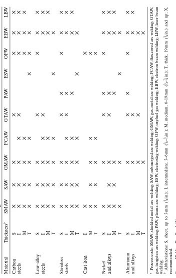
In addition to the melt-in mode adopted in conventional arc welding processes (such as GTAW), the keyholing mode can also be used in PAW in certain ranges of metal thickness (e.g., 2.5–6.4 mm). With proper combinations of the orifice gas flow, the travel speed, and the welding current, keyholing is possi-ble. Keyholing is a positive indication of full penetration and it allows the use of significantly higher welding speeds than GTAW. For example, it has been reported (7) that PAW took one-fifth to one-tenth as long to complete a 2.5-m-long weld in 6.4-mm-thick 410 stainless steel as GTAW. Gas–tungsten arc welding requires multiple passes and is limited in welding speed. As shown in Figure 1.16, 304 stainless steel up to 13 mm (1/
2in.) thick can be welded in a
single pass (8). The wine-cup-shaped weld is common in keyholing PAW.
1.5.4 Advantages and Disadvantages
Plasma arc welding has several advantages over GTAW. With a collimated arc, PAW is less sensitive to unintentional arc length variations during manual welding and thus requires less operator skill than GTAW. The short arc length in GTAW can cause a welder to unintentionally touch the weld pool with the electrode tip and contaminate the weld metal with tungsten. However, PAW does not have this problem since the electrode is recessed in the nozzle. As already mentioned, the keyhole is a positive indication of full penetration, and it allows higher welding speeds to be used in PAW.
However, the PAW torch is more complicated. It requires proper electrode tip configuration and positioning, selection of correct orifice size for the appli-cation, and setting of both orifice and shielding gas flow rates. Because of the
Plasma arc Gas tungsten arc
need for a control console, the equipment cost is higher in PAW than in GTAW. The equipment for variable-polarity PAW is much more expensive than that for GTAW.
1.6 GAS–METAL ARC WELDING
1.6.1 The Process
Gas–metal arc welding (GMAW) is a process that melts and joins metals by heating them with an arc established between a continuously fed filler wire electrode and the metals, as shown in Figure 1.17. Shielding of the arc and the molten weld pool is often obtained by using inert gases such as argon and helium, and this is why GMAW is also called the metal–inert gas (MIG) welding process. Since noninert gases, particularly CO2, are also used, GMAW
seems a more appropriate name. This is the most widely used arc welding process for aluminum alloys. Figure 1.18 shows gas–metal arc welds of 5083 aluminum, one made with Ar shielding and the other with 75% He–25% Ar shielding (9). Unlike in GTAW, DCEP is used in GMAW. A stable arc, smooth metal transfer with low spatter loss and good weld penetration can be obtained. With DCEN or AC, however, metal transfer is erratic.
1.6.2 Shielding Gases
[image:29.441.143.302.66.195.2]Argon, helium, and their mixtures are used for nonferrous metals as well as stainless and alloy steels. The arc energy is less uniformly dispersed in an Ar arc than in a He arc because of the lower thermal conductivity of Ar. Conse-quently, the Ar arc plasma has a very high energy core and an outer mantle of lesser thermal energy. This helps produce a stable, axial transfer of metal
droplets through an Ar arc plasma. The resultant weld transverse cross section is often characterized by a papillary- (nipple-) type penetration pattern (10) such as that shown in Figure 1.18 (left). With pure He shielding, on the other hand, a broad, parabolic-type penetration is often observed.
With ferrous metals, however, He shielding may produce spatter and Ar shielding may cause undercutting at the fusion lines. Adding O2(about 3%)
or CO2 (about 9%) to Ar reduces the problems. Carbon and low-alloy steels
are often welded with CO2as the shielding gas, the advantages being higher (b)
(a)
Shielding gas nozzle
Weld metal Metal
droplet Shielding
gas
Base metal Weld pool
Arc Shielding
gas
Regulator Flow meter
Wire drive & control
Wire reel
Wire electrode
Workpiece Gun
Power
Source Shieldinggas cylinder Welding
direction
Wire electrode Contact tube
Cable 1 Cable 2
Cable 1
[image:30.441.96.340.71.323.2]Figure 1.17 Gas–metal arc welding: (a) overall process; (b) welding area enlarged.
welding speed, greater penetration, and lower cost. Since CO2shielding
pro-duces a high level of spatter, a relatively low voltage is used to maintain a short buried arc to minimize spatter; that is, the electrode tip is actually below the workpiece surface (10).
1.6.3 Modes of Metal Transfer
The molten metal at the electrode tip can be transferred to the weld pool by three basic transfer modes: globular, spray, and short-circuiting.
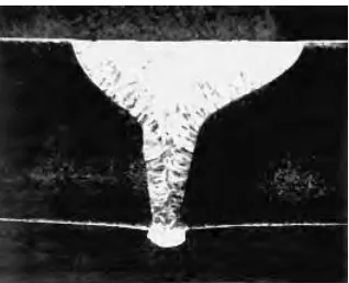
[image:31.441.129.317.340.557.2]A. Globular Transfer Discrete metal drops close to or larger than the electrode diameter travel across the arc gap under the influence of gravity. Figure 1.19a shows globular transfer during GMAW of steel at 180 A and with Ar–2% O2 shielding (11). Globular transfer often is not smooth and
produces spatter. At relatively low welding current globular transfer occurs regardless of the type of the shielding gas. With CO2and He, however,
it occurs at all usable welding currents. As already mentioned, a short buried arc is used in CO2-shielded GMAW of carbon and low-alloy steels to
minimize spatter.
Figure 1.19 Metal transfer during GMAW of steel with Ar–2% O2 shielding: (a)
globular transfer at 180 A and 29 V shown at every 3 ¥ 10-3s; (b) spray transfer at
320 A and 29 V shown at every 2.5 ¥10-4s. Reprinted from Jones et al. (11). Courtesy
B. Spray Transfer Above a critical current level, small discrete metal drops travel across the arc gap under the influence of the electromagnetic force at much higher frequency and speed than in the globular mode. Figure 1.19b
shows spray transfer during GMAW of steel at 320 A and with Ar–2% O2
shielding (11). Metal transfer is much more stable and spatter free. The criti-cal current level depends on the material and size of the electrode and the composition of the shielding gas. In the case of Figure 1.19, the critical current was found to be between 280 and 320 A (11).
C. Short-Circuiting Transfer The molten metal at the electrode tip is trans-ferred from the electrode to the weld pool when it touches the pool surface, that is, when short circuiting occurs. Short-circuiting transfer encompasses the lowest range of welding currents and electrode diameters. It produces a small and fast-freezing weld pool that is desirable for welding thin sections, out-of-position welding (such as overhead-out-of-position welding), and bridging large root openings.
1.6.4 Advantages and Disadvantages
Like GTAW, GMAW can be very clean when using an inert shielding gas. The main advantage of GMAW over GTAW is the much higher deposition rate, which allows thicker workpieces to be welded at higher welding speeds. The dual-torch and twin-wire processes further increase the deposition rate of GMAW (12). The skill to maintain a very short and yet stable arc in GTAW is not required. However, GMAW guns can be bulky and difficult-to-reach small areas or corners.
1.7 FLUX-CORE ARC WELDING
1.7.1 The Process
Flux-core arc welding (FCAW) is similar to GMAW, as shown in Figure 1.20a. However, as shown in Figure 1.20b, the wire electrode is flux cored rather than solid; that is, the electrode is a metal tube with flux wrapped inside. The func-tions of the flux are similar to those of the electrode covering in SMAW, includ-ing protectinclud-ing the molten metal from air. The use of additional shieldinclud-ing gas is optional.
1.8 SUBMERGED ARC WELDING
1.8.1 The Process
and the metals, with the arc being shielded by a molten slag and granular flux, as shown in Figure 1.21. This process differs from the arc welding processes discussed so far in that the arc is submerged and thus invisible. The flux is sup-plied from a hopper (Figure 1.21a), which travels with the torch. No shielding gas is needed because the molten metal is separated from the air by the molten slag and granular flux (Figure 1.21b). Direct-current electrode positive is most often used. However, at very high welding currents (e.g., above 900 A) AC is preferred in order to minimize arc blow. Arc blow is caused by the electro-magnetic (Lorentz) force as a result of the interaction between the electric current itself and the magnetic field it induces.
1.8.2 Advantages and Disadvantages
The protecting and refining action of the slag helps produce clean welds in SAW. Since the arc is submerged, spatter and heat losses to the surrounding air are eliminated even at high welding currents. Both alloying elements and metal powders can be added to the granular flux to control the weld metal composition and increase the deposition rate, respectively. Using two or more electrodes in tandem further increases the deposition rate. Because of its high
(b) (a)
Shielding gas nozzle
Weld metal Base metal Weld pool
Arc Shielding
gas
Regulator Flow meter
Wire drive & control
Wire reel
Wire electrode
Workpiece Gun
Power
Source Shieldinggas cylinder Welding
direction
Wire electrode Contact tube
Cable 1 Cable 2
Cable 1
Slag Metal droplet
[image:33.441.97.345.68.330.2]Flux droplet Shielding gas (optional)
deposition rate, workpieces much thicker than that in GTAW and GMAW can be welded by SAW. However, the relatively large volumes of molten slag and metal pool often limit SAW to flat-position welding and circumferential welding (of pipes). The relatively high heat input can reduce the weld quality and increase distortions.
1.9 ELECTROSLAG WELDING
1.9.1 The Process
Electroslag welding (ESW) is a process that melts and joins metals by heating them with a pool of molten slag held between the metals and continuously feeding a filler wire electrode into it, as shown in Figure 1.22. The weld pool is covered with molten slag and moves upward as welding progresses. A pair of water-cooled copper shoes, one in the front of the workpiece and one behind it, keeps the weld pool and the molten slag from breaking out. Similar to SAW, the molten slag in ESW protects the weld metal from air and refines it. Strictly speaking, however, ESW is not an arc welding process, because the arc exists only during the initiation period of the process, that is, when the arc
Wire reel
Wire electrode
Wire drive & control
Cables Flux hopper
Workpiece
Granular
flux Wire electrode
Arc Molten slag Solidified slag
Metal pool (a)
(b)
Welding direction
Weld metal Base metal
Power Source
[image:34.441.108.333.65.326.2]Droplet
heats up the flux and melts it. The arc is then extinguished, and the resistance heating generated by the electric current passing through the slag keeps it molten. In order to make heating more uniform, the electrode is often oscil-lated, especially when welding thicker sections. Figure 1.23 is the transverse cross section of an electroslag weld in a steel 7 cm thick (13). Typical examples of the application of ESW include the welding of ship hulls, storage tanks, and bridges.
1.9.2 Advantages and Disadvantages
Electroslag welding can have extremely high deposition rates, but only one single pass is required no matter how thick the workpiece is. Unlike SAW or other arc welding processes, there is no angular distortion in ESW because the
Wire electrode
Consumable guide tube
Base metal
Molten slag
Weld pool
Weld metal Cable
Water-cooled copper shoes
Cable Workpiece
Wire reel
Power Source Wire feed motor & control
Bottom support (a)
[image:35.441.114.326.63.413.2](b)
weld is symmetrical with respect to its axis. However, the heat input is very high and the weld quality can be rather poor, including low toughness caused by the coarse grains in the fusion zone and the heat-affected zone. Electroslag welding is restricted to vertical position welding because of the very large pools of the molten metal and slag.
Figure 1.24 summarizes the deposition rates of the arc welding processes discussed so far (14). As shown, the deposition rate increases in the order of
Figure 1.23 Transverse cross section of electroslag weld in 70-mm-thick steel. Reprinted from Eichhorn et al. (13). Courtesy of American Welding Society.
Deposition Rate, Lb/hr
We
lding Process (100% Duty Cycle)
6010 6012 7018
7024 cold wire fine wire
spray
CO2 shielded
with iron powder added 1 electrode
2 electrodes
4 electrodes
5 electrodes 3 electrodes SMAW
GTAW/PAW
GMAW
FCAW
SAW
ESW
0 40 80 120 160 200
Deposition Rate, Kg/hr
80
20 40 60
0
[image:36.441.92.348.244.478.2]iron powder
GTAW, SMAW, GMAW and FCAW, SAW, and ESW. The deposition rate can be much increased by adding iron powder in SAW or using more than one wire in SAW, ESW, and GMAW (not shown).
1.10 ELECTRON BEAM WELDING
1.10.1 The Process
Electron beam welding (EBW) is a process that melts and joins metals by heating them with an electron beam. As shown in Figure 1.25a, the cathode of the electron beam gun is a negatively charged filament (15). When heated up to its thermionic emission temperature, this filament emits electrons. These electrons are accelerated by the electric field between a negatively charged bias electrode (located slightly below the cathode) and the anode. They pass through the hole in the anode and are focused by an electromagnetic coil to a point at the workpiece surface. The beam currents and the accelerating voltages employed for typical EBW vary over the ranges of 50–1000 mA and 30–175 kV, respectively. An electron beam of very high intensity can vaporize the metal and form a vapor hole during welding, that is, a keyhole, as depicted in Figure 1.25b.
Figure 1.26 shows that the beam diameter decreases with decreasing ambient pressure (1). Electrons are scattered when they hit air molecules, and the lower the ambient pressure, the less they are scattered. This is the main reason for EBW in a vacuum chamber.
The electron beam can be focused to diameters in the range of 0.3–0.8 mm and the resulting power density can be as high as 1010W/m2(1). The very high
welding direction
weld bead electron
beam
keyhole weld pool
cross-section of weld
(b) moten metal electron
beam
specimen bias
electrode anode
focusing coil
to pump
high voltage cathode
(a) vacuum
chamber
power density makes it possible to vaporize the material and produce a deep-penetrating keyhole and hence weld. Figure 1.27 shows a single-pass electron beam weld and a dual-pass gas–tungsten arc weld in a 13-mm-thick (0.5-in.) 2219 aluminum, the former being much narrower (16). The energy required per unit length of the weld is much lower in the electron beam weld (1.5 kJ/cm, or 3.8 kJ/in.) than in the gas–tungsten arc weld (22.7 kJ/cm, or 57.6 kJ/in.).
Electron beam welding is not intended for incompletely degassed materi-als such as rimmed steels. Under high welding speeds gas bubbles that do not have enough time to leave deep weld pools result in weld porosity. Materials containing high-vapor-pressure constituents, such as Mg alloys and Pb-containing alloys, are not recommended for EBW because evaporation of these elements tends to foul the pumps or contaminate the vacuum system.
1.10.2 Advantages and Disadvantages
With a very high power density in EBW, full-penetration keyholing is possi-ble even in thick workpieces. Joints that require multiple-pass arc welding can
[image:38.441.159.279.285.363.2]750 torr 500 torr 250 torr 50 torr 5 torr
Figure 1.26 Dispersion of electron beam at various ambient pressures (1). Reprinted from Welding Handbook (1). Courtesy of American Welding Society.
13 mm (0.5 in) electron
beam weld
gas tungsten arc weld
(a) (b)
be welded in a single pass at a high welding speed. Consequently, the total heat input per unit length of the weld is much lower than that in arc welding, resulting in a very narrow heat-affected zone and little distortion. Reactive and refractory metals can be welded in vacuum where there is no air to cause contamination. Some dissimilar metals can also be welded because the very rapid cooling in EBW can prevent the formation of coarse, brittle intermetal-lic compounds. When welding parts varying greatly in mass and size, the ability of the electron beam to precisely locate the weld and form a favorably shaped fusion zone helps prevent excessive melting of the smaller part.
However, the equipment cost for EBW is very high. The requirement of high vacuum (10-3–10-6torr) and x-ray shielding is inconvenient and time
con-suming. For this reason, medium-vacuum (10-3–25 torr) EBW and nonvacuum
(1 atm) EBW have also been developed. The fine beam size requires precise fit-up of the joint and alignment of the joint with the gun. As shown in Figure 1.28, residual and dissimilar metal magnetism can cause beam deflection and result in missed joints (17).
1.11 LASER BEAM WELDING
1.11.1 The Process
Laser beam welding (LBW) is a process that melts and joins metals by heating them with a laser beam. The laser beam can be produced either by a
solid-Missed joint
48356 47421
[image:39.441.117.331.65.272.2]A387 SB49
Figure 1.28 Missed joints in electron beam welds in 150-mm-thick steels: (a) 2.25Cr–1Mo steel with a transverse flux density of 3.5 G parallel to joint plane; (b) SB (C–Mn) steel and A387 (2.25Cr–1Mo) steel. Reprinted from Blakeley and Sanderson (17). Courtesy of American Welding Society.
state laser or a gas laser. In either case, the laser beam can be focused and directed by optical means to achieve high power densities. In a solid-state laser, a single crystal is doped with small concentrations of transition elements or rare earth elements. For instance, in a YAG laser the crystal of yttrium– aluminum–garnet (YAG) is doped with neodymium. The electrons of the dopant element can be selectively excited to higher energy levels upon expo-sure to high-intensity flash lamps, as shown in Figure 1.29a. Lasing occurs when these excited electrons return to their normal energy state, as shown in Figure 1.29b. The power level of solid-state lasers has improved significantly, and con-tinuous YAG lasers of 3 or even 5 kW have been developed.
In a CO2laser, a gas mixture of CO2, N2, and He is continuously excited
by electrodes connected to the power supply and lases continuously. Higher
(a) Power
source
Cooling system Reflecting mirror
Patially reflecting mirror Focusing lens
Travel direction
Pool Weld
Workpiece
Cr
ystal
High intensity flash lamp
(b) energy absorbed
from flash lamp
energy emitted as heat
energy emitted as light (photon)
nucleus ground intermediate excited
inner electrons
outer electron energy levels
[image:40.441.121.321.236.577.2]normal electron orbits
power can be achieved by a CO2laser than a solid-state laser, for instance,
15 kW. Figure 1.30ashows LBW in the keyholing mode. Figure 1.30bshows a weld in a 13-mm-thick A633 steel made with a 15-kW CO2laser at 20 mm/s
(18).
Besides solid-state and gas lasers, semiconductor-based diode lasers have also been developed. Diode lasers of 2.5 kW power and 1 mm focus diameter have been demonstrated (19). While keyholing is not yet possible, conduction-mode (surface melting) welding has produced full-penetration welds with a depth–width ratio of 3 : 1 or better in 3-mm-thick sheets.
1.11.2 Reflectivity
The very high reflectivity of a laser beam by the metal surface is a well-known
problem in LBW. As much as about 95% of the CO2 beam power can be
reflected by a polished metal surface. Reflectivity is slightly lower with a YAG laser beam. Surface modifications such as roughening, oxidizing, and coating can reduce reflectivity significantly (20). Once keyholing is established, absorp-tion is high because the beam is trapped inside the hole by internal reflecabsorp-tion.
1.11.3 Shielding Gas
A plasma (an ionic gas) is produced during LBW, especially at high power levels, due to ionization by the laser beam. The plasma can absorb and scatter the laser beam and reduce the depth of penetration significantly. It is there-fore necessary to remove or suppress the plasma (21). The shielding gas for protecting the molten metal can be directed sideways to blow and deflect the plasma away from the beam path. Helium is often preferred to argon as the shielding gas for high-power LBW because of greater penetration depth (22).
welding direction
weld
bead laser
beam
keyhole weld pool
cross-section of weld
(a) (b)
molten metal
2 mm
Figure 1.30 Laser beam welding with CO2laser: (a) process; (b) weld in 13-mm-thick
Since the ionization energy of helium (24.5 eV) is higher than that of argon (15.7 eV), helium is less likely to be ionized and become part of the plasma than argon. However, helium is lighter than air and is thus less effective in dis-placing air from the beam path. Helium–10% Ar shielding has been found to improve penetration over pure He at high-speed welding where a light shielding gas may not have enough time to displace air from the beam path (23).
1.11.4 Lasers in Arc Welding
As shown in Figure 1.31, laser-assisted gas metal arc welding (LAGMAW) has demonstrated significantly greater penetration than conventional GMAW (24). In addition to direct heating, the laser beam acts to focus the arc by heating its path through the arc. This increases ionization and hence the con-ductivity of the arc along the beam path and helps focus the arc energy along the path. It has been suggested that combining the arc power with a 5-kW CO2
laser, LAGMAW has the potential to achieve weld penetration in mild steel equivalent to that of a 20–25-kW laser (24). Albright et al. (25) have shown that a lower power CO (not CO2) laser of 7 W and 1 mm diameter can
initi-ate, guide, and focus an Ar–1% CO gas–tungsten arc.
1.11.5 Advantages and Disadvantages
Like EBW, LBW can produce deep and narrow welds at high welding speeds, with a narrow heat-affected zone and little distortion of the workpiece. It can
LAGMAW GMAW
300 400 500 600 700
0 2 4 6 8 10 12
Welding current (A)
P
enetr
[image:42.441.138.304.407.578.2]ation (mm)
Figure 1.31 Weld penetration in GMAW and laser-assisted GMAW using CO2laser
be used for welding dissimilar metals or parts varying greatly in mass and size. Unlike EBW, however, vacuum and x-ray shielding are not required in LBW. However, the very high reflectivity of a laser beam by the metal surface is a major drawback, as already mentioned. Like EBW, the equipment cost is very high, and precise joint fit-up and alignment are required.
REFERENCES
1. Welding Handbook, Vol. 3, 7th ed., American Welding Society, Miami, FL, 1980, pp. 170–238.
2. Mendez, P. F., and Eagar, T. W., Advanced Materials and Processes, 159: 39, 2001.
3. Welding Handbook,Vol. 1, 7th ed., American Welding Society, Miami, FL, 1976, pp. 2–32.
4. Welding Workbook, Data Sheet 212a,Weld. J.,77:65, 1998.
5. Welding Handbook, Vol. 2, 7th ed., American Welding Society, Miami, FL, 1978, pp. 78–112, 296–330.
6. Lyttle, K. A., in ASM Handbook, Vol. 6, ASM International, Materials Park, OH, 1993, p. 64.
7. Schwartz, M. M.,Metals Joining Manual, McGraw-Hill, New York, 1979, pp. 2–1 to 3– 40.
8. Lesnewich, A., inWeldability of Steels, 3rd ed., Eds. R. D. Stout and W. D. Doty, Welding Research Council, New York, 1978, p. 5.
9. Gibbs, F. E.,Weld. J.,59:23, 1980.
10. Fact Sheet—Choosing Shielding for GMA Welding,Weld. J.,79:18, 2000. 11. Jones, L. A., Eagar, T. W., and Lang, J. H.,Weld. J.,77:135s, 1998.
12. Blackman, S. A., and Dorling, D. V.,Weld. J.,79:39, 2000. 13. Eichhorn, F., Remmel, J., and Wubbels, B.,Weld. J.,63:37, 1984.
14. Cary, H. B., Modern Welding Technology, Prentice-Hall, Englewood Cliffs, NJ, 1979.
15. Arata, Y.,Development of Ultra High Energy Density Heat Source and Its Appli-cation to Heat Processing, Okada Memorial Japan Society, 1985.
16. Farrell, W. J.,The Use of Electron Beam to Fabricate Structural Members, Creative Manufacturing Seminars, ASTME Paper SP 63-208, 1962–1963.
17. Blakeley, P. J., and Sanderson, A.,Weld. J.,63:42, 1984.
18. Metzbower, E. A., private communication, Naval Research Laboratory, Washington, DC.
19. Bliedtner, J., Heyse, Th., Jahn, D., Michel, G., Muller, H., and Wolff, D.,Weld. J.,80: 47, 2001.
20. Xie, J., and Kar, A.,Weld. J.,78:343s, 1999.
21. Mazumder, J., in ASM Handbook, Vol. 6, ASM International, Materials Park, OH, 1993, p. 874.
23. Seaman, F.,Role of Shielding Gas in Laser Welding, Technical Paper MR77-982, Society of Manufacturing Engineers, Dearborn, MI, 1977.
24. Hyatt, C. V., Magee, K. H., Porter, J. F., Merchant, V. E., and Matthews, J. R.,Weld. J.,80:163s, 2001.
25. Albright, C. E., Eastman, J., and Lempert, W.,Weld. J.,80:55, 2001.
26. Ushio, M., Matsuda, F., and Sadek, A. A., in “ International Trends in Welding Science and Technology, Eds. S. A. David and J. M. Vitek, ASM International, Materials Park, OH, March 1993, p. 408.
FURTHER READING
1. Arata, Y.,Development of Ultra High Energy Density Heat Source and Its Applica-tion to Heat Processing, Okada Memorial Society for the Promotion of Welding, Japan, 1985.
2. Schwartz, M. M.,Metals Joining Manual, McGraw-Hill, New York, 1979.
3. Welding Handbook, Vols. 1–3, 7th ed., American Welding Society, Miami, FL, 1980.
4. Duley, W. W.,Laser Welding, Wiley, New York, 1999.
5. ASM Handbook, Vol. 6, ASM International, Materials Park, OH, 1993.
PROBLEMS
1.1 It has been suggested that compared to SMAW, the cooling rate is higher in GMAW and it is, therefore, more likely for heat-affected zone cracking to occur in hardenable steels. What is the main reason for the cooling rate to be higher in GMAW than SMAW?
1.2 The diameter of the electrodes to be used in SMAW depends on factors such as the workpiece thickness, the welding position, and the joint design. Large electrodes, with their corresponding high currents, tend to produce large weld pools. When welding in the overhead or vertical position, do you prefer using larger or smaller electrodes?
1.3 In arc welding, the magnetic field induced by the welding current passing through the electrode and the workpiece can interact with the arc and cause “arc blow.” Severe arc blow can cause excessive weld spatter and incomplete fusion. When arc blow is a problem in SMAW, do you expect to minimize it by using DC or AC for welding?
be more than doubled this way. Do you prefer using an AC or a DC power source for heating the wire? Do you expect to apply this process to aluminum and copper alloys?
1.5 In GTAW the welding cable is connected to the tungsten electrode through a water-cooled copper contact tube, as shown in Figure 1.11. Why is the tube positioned near the lower end of the electrode instead of the top?
1.6 Measurements of the axial temperature distribution along the GTAW electrode have shown that the temperature drops sharply from the electrode tip toward the contact tube. Why? For instance, with a 2.4-mm-diameter W–ThO2 electrode at 150 A, the temperature drops
from about 3600 K at the tip to about 2000 K at 5 mm above the tip. Under the same condition but with a W–CeO2electrode, the
tempera-ture drops from about 2700 K at the tip to about 1800 K at 5 mm above the tip (26). Which electrode can carry more current before melting and why?
1.7 Experimental results show that in EBW the penetration depth of the weld decreases as the welding speed increases. Explain why. Under the same power and welding speed, do you expect a much greater penetra-tion depth in aluminum or steel and why?
1.8 How does the working distance in EBW affect the depth–width ratio of the resultant weld?
1.9 Consider EBW in the presence of a gas environment. Under the same power and welding speed, rank and explain the weld penetration for Ar, He, and air. The specific gravities of Ar, He, and air with respect to air are 1.38, 0.137, and 1, respectively, at 1 atm, 0°C.
Shielding gas nozzle
Weld metal Shielding gas
Base metal Weld pool
Arc
Tungsten electrode Contact tube
Cable 1 Wire feeder
Filler wire
2nd power source
Cable 3
Cable 4
Contact tube
1.10 Which arc welding process could have been used for joining the edge weld of thin-gauge steel shown in Figure P1.10 and why?
1.11 Two 15-cm-thick steel plates were joined together in a single pass, as shown in Figure P1.11. Which welding process could have been used and why?
weld
1 mm
1 mm
[image:46.441.150.288.63.259.2]transverse cross-section
Figure P1.10
15 cm
15 cm
weld transverse
cross-section steel
steel
2
Heat Flow in Welding
Heat flow during welding, as will be shown throughout Parts II–IV of this book, can strongly affect phase transformations during welding and thus the resultant microstructure and properties of the weld. It is also responsible for weld residual stresses and distortion, as will be discussed in Chapter 5.
2.1 HEAT SOURCE
2.1.1 Heat Source Efficiency
A. Definition The heat source efficiencyhis defined as
(2.1)
where Q is the rate of heat transfer from the heat source to the workpiece,
Qnominal the nominal power of the heat source, and tweld the welding time. A portion of the power provided by the heat source is transferred to the work-piece and the remaining portion is lost to the surroundings. Consequently, h< 1. If the heat source efficiency his known, the heat transfer rate to the workpiece,Q, can be easily determined from Equation (2.1).
In arc welding with a constant voltage Eand a constant current I, the arc efficiency can be expressed as
(2.2)
Equation (2.2) can also be applied to electron beam welding, where his the heat source efficiency. In laser beam welding,Qnominalin Equation (2.1) is the
power of the laser beam, for instance, 2500 W.
It should be noted that in the welding community the term heat inputoften refers to Qnominal, or EIin the case of arc welding, and the term heat input per unit length of weldoften refers to the ratio Qnominal/V, or EI/V, where V is the
welding speed.
B. Measurements The heat source efficiency can be measured with a calorimeter. The heat transferred from the heat source to the workpiece is in
h= Qt =
EIt
Q EI weld
weld
h= Qt =
Q t
Q Q weld
nominal weld nominal
turn transferred from the workpiece to the calorimeter, which can be deter-mined as described below.
Kou et al. (1, 2) used simple tubular calorimeters to determine the arc efficiency in GTAW of aluminum, as shown in Figure 2.1a. The calorimeter can be a round cross section if the workpiece is a pipe or a rectangular cross section if the workpiece is a sheet. The temperature rise in the cool-ing water (Tout - Tin) can be measured using thermocouples or thermistors.
Heat transfer from the workpiece to the calorimeter is as follows (1– 3):
(2.3)
where Wis the mass flow rate of water,Cthe specific heat of water,Toutthe
outlet water temperature,Tinthe inlet water temperature, and ttime. The
inte-gral corresponds to the shaded area in Figure 2.1b. The arc efficiency hcan be determined from Equations (2.2) and (2.3).
Giedt et al. (4) used the Seebeck envelop calorimeter shown in Figure 2.2a
to measure the arc efficiency in GTAW. The name Seebeck came from the Seebeck thermoelectric effect of a thermocouple, namely, a voltage is produced between two thermocouple junctions of different temperatures. The torch can be quickly withdrawn after welding, and the calorimeter lid can be closed to minimize heat losses to the surrounding air. As shown in Figure 2.2b, heat transfer from the workpiece to the calorimeter can be determined by measuring the temperature difference DTand hence gradient
Qtweld = WC T
(
out-Tin)
dtªWC(
Tout-T dtin)
• •
Ú
0Ú
0GTAW torch Pipe Water out Thermocouple Thermocouple Water in Insulation Arc Time, seconds T emper ature , oC T emper ature , oF (a) (b) 100 120 120 100 80 20 30 40 50 Tout Tin Shaded area ∞
=
∫
[ out- in ]dt [image:48.441.126.311.68.261.2]0 T T
across a “gradient layer” of material of known thermal conductivity k and thickness L:
(2.4)
Qt A k T
L dt weld=
•
Ú
0 D TL
Cooling water flow
Gradient layer
Thermocouple junctions for sensing
temperature difference
Direction of heat flow
T
emper
ature
Distance
[image:49.441.50.379.64.484.2]Temperature profile ∆
Figure 2.2 Measurement of arc efficiency in GTAW: (a) calorimeter; (b) layer of tem-perature gradient. Reprinted from Giedt et al. (4). Courtesy of American Welding Society.
(a)