http://www.scirp.org/journal/wjet ISSN Online: 2331-4249
ISSN Print: 2331-4222
DOI: 10.4236/wjet.2019.71015 Feb. 19, 2019 227 World Journal of Engineering and Technology
Development of Autonomous VTOL UAV for
Wide Area Surveillance
Daeil Jo, Yongjin Kwon
*Department of Industrial Engineering, College of Engineering, Ajou University, Suwon, South Korea
Abstract
The drone was developed with the use of unmanned aircraft systems in the initial military sector based on the combination of aerospace technology and information and communication technologies in a variety of usability, in-cluding the civilian sectors. Developed for the field of reconnaissance, it is used in both civilian and police sectors as traffic monitoring and high altitude reconnaissance missions. It is used in broadcasting and surveillance, while continuously expanding into the areas of courier delivery and rescue mis-sions. Based on the convergence of aviation technology such as various SW, sensor and flight control to utilize unmanned system and information com-munication technology, commercialization of related technology is being de-veloped as a very diverse route. In this paper, we propose and manufacture of a VTOL UAV. Design process referred to the VTOL development process that has been devised by us, and actual building of a UAV also applied the same VTOL development concept. In order to understand the aerodynamic cha-racteristics of the aircraft, we have applied the aerodynamic design theory and used the CAE method that can replace the actual wind tunnel test. We tested the selection method and criteria for the internal modules that make up the UAV, and we were able to assemble the product. FW coding of flight control computer was conducted for VTOL control. In addition, we developed a LTE communication module for the long distance flight, and carried out flight experiments with GCS to observe and respond to the flight situation from the ground. Flight test results showed that stable transition flight was possible with broadband. We could see that the actual performance results were met, compared to our development target values.
Keywords
UAV, VTOL, Fixed Wing, Drone, Multi-Copter, Rotary Wing, Aircraft Design, Transition Flight
How to cite this paper: Jo, D. and Kwon, Y. (2019) Development of Autonomous VTOL UAV for Wide Area Surveillance. World Journal of Engineering and Tech-nology, 7, 227-239.
https://doi.org/10.4236/wjet.2019.71015
Received: January 16, 2019 Accepted: February 16, 2019 Published: February 19, 2019 Copyright © 2019 by author(s) and Scientific Research Publishing Inc. This work is licensed under the Creative Commons Attribution International License (CC BY 4.0).
DOI: 10.4236/wjet.2019.71015 228 World Journal of Engineering and Technology generate a wing-lift due to the characteristics of propellant types, which shortens the flight time. On the other hand, the fixed-wing type UAV has an advantage of longer flight time and higher speed, but it is difficult to secure a wide space for safe landing. This has been a great limitation in utilization. This study aims to develop a VTOL (vertical takeoff and landing) UAV, utilizing the advantages of both multi-copter type and fixed-wing type UAV [1] [2] [3].
2. The VTOL Development Process
The overall development process of the vertical takeoff and landing VTOL UAV performed in this study is shown in Figure 1. This is based on our genuine effort to establish a systematic and sound UAV development, which has been mainly based on each developer.
2.1. Body Frame Design
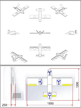
[image:2.595.227.520.469.703.2]The airframe design is an important part of the UAV development designed to reduce the air resistance. Compared to the quad-X type design (a typical mul-ti-copter design), it is aesthetically and aerodynamically superior. Shown in Fig-ure 2, its design ensures a large mounting space at the center of the fuselage to load various mission equipment and cargo [4].
DOI: 10.4236/wjet.2019.71015 229 World Journal of Engineering and Technology
Figure 2. Body frame design layout.
2.2. Wing & Fuselage Design
Wing is an important part of determining the performance of UAV. The wing can be designed in various ways, such as low-wing, mid-wing and high-wing, which is mainly dependent on the desired flight characteristics. In the case of the lower wing, it has the merit that it can increase the maneuverability. In the case of the central wing, the balance of frame is said to be the best. Using the CAE (computer-aided engineering) software, the design of the wing shape was ana-lyzed. The flight dynamic characteristics such as air resistance, lift, curvature analysis, airfoil, and air flow, are shown in Figure 3. The experimental condi-tions are boundary condicondi-tions when flying at 0˚C and 15 m/s. In the previous study, we designed the airfoil for the VTOL design as shown in Figure 4, and developed the airfoil which can achieve the efficiency at a low speed, considering that the maximum speed is 80 km/h and the cruising speed is 60 km/h [5] [6] [7].
2.3. Selection of Motor Thrust
DOI: 10.4236/wjet.2019.71015 230 World Journal of Engineering and Technology
Figure 3. CAE simulation Analysis 1.
Figure 4. CAE simulation Analysis 2.
The thrust determination equation is shown in Equation (1). Also, the equation to determine the propeller for generating the thrust after determining the re-quired thrust is shown in Equation (2) [8].
Power = Prop Const × rpmPower factor (1)
2
4
T =π D ρv v∆ (2)
T: thrust [N].
D: propeller diameter [m].
v: velocity of air the propeller [m/s].
∆v: velocity of air the accelerated by propeller [m/s].
ρ: density of air [1.225 kg/m3].
2.4. Selection of Propellers
[image:4.595.232.526.61.243.2]DOI: 10.4236/wjet.2019.71015 231 World Journal of Engineering and Technology leads to the decrease of the flight time. Therefore, it is necessary to select the proper propeller, according to the size of the airframe and the specification of the motor. Based on the motor selected in this way, the propeller is selected us-ing Equation (3) from the source of known reference [9] (Figure 5).
1 3 3 1 2 2 2 ideal 2
rpm g m
D
ω ω
π α ρ
=
(3)
ω = Power Factor from Aircraft. α = Power Coefficient from Aircraft. D = Diameter [m].
ρ = Air Density [1.225 kg/m3].
m = Mass [kg].
g = Gravity [9.8 m/s3].
2.5. Selection of ESC & Power Pack
The ESC (electronic speed control) is a device that can control the direction and speed of the drone motors. It can supply the proper voltage, depending on the motor or battery and is designed to handle the maximum current used by the motor. Figure 6 shows the selected ESC of 40 A.
The battery is directly related to the flight time. Equation (4) represents the flight time, according to the capacity and the consumption current of the bat-tery.
Flight time = Battery capacity/amp (4)
(
) ( )
60 min 1 hour Fl
8 ight time 2
A (1000 000 0mA mAh 15min ) A = ∗ ∗ ∗ =
The battery in this study was selected as 6 Cell, 24 V, 10,000 mAh type, consi-dering flight time and thrust. Here, the “mAh” indicates the capacity of the bat-tery. For example, an indication of 100,000 mAh means that you can use 1 hour when you draw 10,000 mA. The “V” indicates the voltage. One must use a bat-tery with the proper voltage to stabilize the current to the drive motors.
[image:5.595.215.534.573.705.2]The “Wh” shows how much power the battery has. This value can be calculated
DOI: 10.4236/wjet.2019.71015 232 World Journal of Engineering and Technology
Figure 6. Selection of 40A ESC.
by multiplying the capacity mAh with the voltage V. The “C” indicates the dis-charge rate. In this study, we used the Motocalc SW, as shown in Figure 7. This software predicts the flight performance according to the parameters of the mo-tor and propeller. The propeller length was 14 inches and the battery was HBZ-B 5200 22.2 V. The motor was selected as Quantum 400 kv. As a result, it was es-timated that the thrust was about 12 kg or more. It is designed to be more than 3 times the weight of the airframe and enough to lift the airframe vertically with a 3 Kg load. Table 1 shows the VTOL specifications produced by the study [10] [11] [12].
3. VTOL Assembly
3.1. Airframe Manufacturing
The designed UAV parts are produced by using a 3D printer and the UAV is as-sembled as shown in Figure 8. The 3D printed parts were mainly used to test and evaluate our initial design.
The final frame was produced after identified problems were solved, based on the data obtained from the prototype production. Figure 9 and Figure 10 show the process of fabricating and assembling the final airframe [13] [14].
3.2. Flight Control Computer FW Coding for VTOL Control
The software setting is the core of FCC (flight control computer) coding. The FCC has built in components such as accelerometer, gyro, geomagnetic, baro-meter, GPS (global positioning system) and CPU (central processing unit), to maintain the stabilized flight by sensing the equilibrium state of VTOL. The geomagnetic system measures the movement direction of the airframe, while the barometer measures the altitude of the VTOL. The GPS tracks the flight routes of the UAV and performs the mission profile. In this study, FW (firmware) is coded using the Pixhawk controller, which is the most used FCC. The Pixhawk is an open source, and FW coding was developed as shown in Figure 11, using the C-language [15].
3.3. Development of LTE Communication Module
DOI: 10.4236/wjet.2019.71015 233 World Journal of Engineering and Technology
Table 1. VTOL specifications.
Contents Specifications Length 1200 mm Wing Span 1950 mm Empty Weight 3.9 Kg Horizontal Thrust 3.0 kg Vertical Thrust 12.0 kg
[image:7.595.262.487.451.533.2]Power Pack 6 Cell, 24 V, 10,000 mAh
[image:7.595.268.480.562.708.2]Figure 7. Thrust calculation using Motocalc S/W.
Figure 8. Fuselage sections of the 3D printed parts.
DOI: 10.4236/wjet.2019.71015 234 World Journal of Engineering and Technology
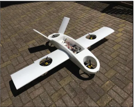
Figure 10. Completed VTOL UAV.
[image:8.595.221.527.264.700.2]DOI: 10.4236/wjet.2019.71015 235 World Journal of Engineering and Technology by looking at the airframe. The UAV can be controlled in real-time, using 5.8 Ghz of for analog video transfer and 2.4 Ghz of frequency for the manipulator. When flying a long distance, it can be controlled through the LTE (long-term evolution) communication by using the automatic flight function. By developing a library to connect FCC and LTE modem, the UAV pilot can remotely check the flight images and UAV status, while controlling the UAV beyond the line-of-sight. As shown in Figure 12, the LTE modem developed in this study can be easily added in the future.
3.4. Ground Control Station Design and Production
For the remote control of UAV, the GCS (ground control station) is developed. The GUI-based (graphical user interface-based) environment and a user-friendly user interface have been developed, so that the flight status can be observed and confirmed on a map screen. The UAV flight control is equipped with both au-tomatic flight and manual flight. As shown in Figure 13, the touch-screen dis-plays the preprogrammed flight path. The control button layout is configured to increase the usability [16] [17] [18] [19].
4. VTOL Flight Experiments
[image:9.595.290.460.402.536.2]In this section, we analyzed the flight characteristics of the developed VTOL. Through numerous trials and errors, we have optimally set up the flight parameters
Figure 12. Self-developed LTE modem.
[image:9.595.287.458.571.705.2]DOI: 10.4236/wjet.2019.71015 236 World Journal of Engineering and Technology
Figure 14. Preparatory work for flight experiments.
[image:10.595.217.531.364.605.2]Figure 15. Automatic route flight.
Table 2. Comparison of the development goals with the actual performance data.
Spec Unit Target Before Study After Study Goal Flight Time min ≥60 20 65.9 Satisfied
[image:10.595.210.540.657.728.2]DOI: 10.4236/wjet.2019.71015 237 World Journal of Engineering and Technology
Continued
[image:11.595.211.537.86.436.2]Vertical Ascent Rate m/s ≥3.0 2 8 Satisfied Vertical Descent Speed m/s ≥4.0 1 50 Satisfied Horizontal Flight Speed Km/h ≥80 Km/h 45 108 Satisfied Wireless Distance Km LTE Networks Satisfied Bank Angle Angle ±45 20 +71, −65 Satisfied Pitch Angle Angle ±25 20 +34, −25 Satisfied Maximum Load Weight Kg ≥3.0 1 3 more Satisfied
Figure 16. Profile of the VTOL flight experiments.
Figure 17. Log data extracted from the flight experiments.
5. Conclusion
[image:11.595.208.539.462.656.2]manu-DOI: 10.4236/wjet.2019.71015 238 World Journal of Engineering and Technology UAV, and we were able to assemble the product. Firmware coding of the flight control computer was conducted as well. In addition, we developed a LTE communication module for long distance flight, and carried out flight experi-ments with the GCS to observe and monitor the flight status from the ground. Flight tests showed that a stable transition flight was possible with our method and we could see that the actual performance results were met compared to the development target.
Acknowledgements
Following are results of a study on the “Leaders in Industry-University Coopera-tion+” Project, supported by the Ministry of Education and National Research Foundation of Korea.
Conflicts of Interest
The authors declare no conflicts of interest regarding the publication of this pa-per.
References
[1] Jo, D. and Kwon, Y. (2017) Analysis of VTOL UAV Propellant Technology. Journal of Computer and Communications, 5, 76-82.https://doi.org/10.4236/jcc.2017.57008
[2] Jo, D. and Kwon, Y. (2017) Development of Rescue Material Transport UAV.
World Journal of Engineering and Technology, 5, 720-729.
https://doi.org/10.4236/wjet.2017.54060
[3] Kim, K.B. (2013) Design and Verification of Multi-Rotor Based Unmanned Aerial Vehicle System. Ph.D. Thesis, Department of Mechanical Engineering, Konkuk University, South Korea.
[4] Lee, C.J. (2017) Aircraft Structural Design Practice. Good Land-Company, McMinnville.
[5] kevadiya, M. (2013) CFD Analysis of Pressure Coefficient for NACA 4412. Interna-tional Journal of Engineering Trends and Technology (IJETT), 4, 2041-2043. [6] Yun, S.J. (2010) Aerodynamics. Saintian-Company, Pajoo.
[7] SOLIDWORKS 2017 (2017) Structural Analysis & Flow Simulation.
[8] Green, W.E. and Oh, P.Y. (2006) Autonomous Hovering of a Fixed-Wing Micro Air Vehicle. IEEE International Conference of Automation (ICRA), Orlando, 15-19 May 2006, 2164-2169.
[9] https://quadcopterproject.wordpress.com
DOI: 10.4236/wjet.2019.71015 239 World Journal of Engineering and Technology
in Drone Flight Training Simulators. Computers in Human Behavior, 64, 449-454. [11] Liu, Z. and Li, H. (2016) Research on Visual Objective Test Method of High-Level
Flight Simulator. Journal of System Simulation, 7, 1609-1614.
[12] Luan, L.-N. (2013) Augmenting Low-Fidelity Flight Simulation Training Devices via Amplified Head Rotations. Loughborough University,Loughborough.
[13] Lee, S. and Lim, K. (2008) PCB Design Guide Book. Sehwa Publishing Co., South Korea.
[14] Kang, M. and Shin, K. (2011) Electronic Circuit. Hanbit Media, Seoul.
[15] Yoon, H. (2015) Mitigation Settings and Their Execution Scenario in Drone Firm-ware. International Research Journal of Computer Science (IRJCS), 2, 7-11.
[16] Lee, E., Kim, S. and Kwon, Y. (2016) Analysis of Interface and Screen for Ground Control System. Journal of Computer and Communications, 4, 61-66.
https://doi.org/10.4236/jcc.2016.45009
[17] Kwon, Y., Heo, J., Jeong, S., Yu, S. and Kim, S. (2016) Analysis of Design Directions for Ground Control Station (GCS). Journal of Computer and Communications,4,
1-7.https://doi.org/10.4236/jcc.2016.415001
[18] Yu, S., Heo, J., Jeong, S. and Kwon, Y. (2016) Technical Analysis of VTOL UAV.
Journal of Computer and Communications,4, 92-97.
https://doi.org/10.4236/jcc.2016.415008