ISSN Online: 2327-4379 ISSN Print: 2327-4352
DOI: 10.4236/jamp.2018.69166 Sep. 30, 2018 1951 Journal of Applied Mathematics and Physics
Numerical Simulation of the Churning Power
Losses in the Automotive Hypoid Gear Reducer
Lin Zou, Mingya Du, Bing Jia, Jinli Xu, Liangshun Ren
School of Mechanical and Electronic Engineering, Wuhan University of Technology, Wuhan, China
Abstract
Improving vehicle transmission efficiency and reducing vehicle fuel con-sumption is currently one of the main objectives in the automotive field. Re-ducing gear churning power losses has significant influence on the decreas-ing vehicle fuel consumption. Based on the two phase flow theory, a 2D two-phase model of the simplified hypoid gear is established to predict the churning losses in different conditions, the VOF method is introduced to track the volume fraction of the free surface, a standard k-ε model is also built to calculate complex turbulence. The oil distributions at the different rota-tional speed, the different immersion depth and the different viscosity as well as the churning losses of the hypoid gear are obtained and discussed in detail. In general, the churning power losses increase with the increase of the speed, the immersion depth and the viscosity, while the rotational speed shows the greatest influence on the churning losses. It is hoped that this investigation will be helpful in automotive industry applications.
Keywords
Churning Power Loss, Two Phases Flow, VOF Method, Hypoid Gear
1. Introduction
The internal transmission efficiency of the rear axle of a car directly affects the oil consumption of the whole vehicle. The gears and bearings, as the main com-ponents of the rear axle, play a key impact on the transmission efficiency of the rear axle. It is critical to figure out the mechanism of its efficiency losses to re-duce the oil consumption of the whole vehicle.
In the last years, the churning losses of the gears have been the subject of ex-tensive numerical and experimental investigations. Concli & Gorla computa-tionally and experimentally analyzed the churning power losses in an industrial
How to cite this paper: Zou, L., Du, M.Y., Jia, B., Xu, J.L. and Ren, L.S. (2018) Nu-merical Simulation of the Churning Power Losses in the Automotive Hypoid Gear Reducer. Journal of Applied Mathematics and Physics, 6, 1951-1956.
https://doi.org/10.4236/jamp.2018.69166
DOI: 10.4236/jamp.2018.69166 1952 Journal of Applied Mathematics and Physics planetary speed reducers and point out that the VOF method could provide more information on the physical phenomena than any experimental measure-ment [1]. And then they developed a new approach to predict churning power losses of ordinary gears [2]. Kodela et al. proposed a CFD method to estimate the splash loss for the complete manual transmission gear box at the different operating conditions such as the rotational speed, the temperature and the oil level [3]. Liu et al. numerically investigated the oil distribution and the churning loss of a single-stage gearbox by the finite volume CFD method, and showed that the turbulence of oil increased with the increase of the rotational speed [4]. Wang et al. numerically investigated the churning losses of the spur gear, but found out that there are big differences between simulation values and theoreti-cal theoreti-calculation [5]. Concli & Gorla further pointed out that the power losses were not directly decreased with the increase of the temperature, and an optimal temperature existed [6].
The above literatures mostly pay attention to investigating the churning losses of the spur gear. However, less investigation on the churning losses of the hypo-id gears is discussed. In the present study, the oil distribution of the hypohypo-id gear at the different conditions and the influencing factors of the churning losses such as the speed, the immersion depth and the viscosity are obtained and dis-cussed. It is hoped that this investigation will be helpful for the deepening of our understanding on the oil consumption of the whole vehicle.
2. Governing Equations and Numerical Method
The numerical method stated in this paper depends on the solution of two go-verning equations that mathematically represent the conservation laws of mass and momentum [7]:
0
i i
u x
∂ =
∂ (1)
( )
i j 1 ji i
i
i i i i j
u u u
u p u f
t x ρ x η x x x
∂ ∂
∂ ∂ ∂ ∂
+ = − + + +
∂ ∂ ∂ ∂ ∂ ∂ (2)
where ui is velocity in the xi direction. Where p is pressure, ρ is mixture
density, η is the mixture viscosity, ui is velocity in the yi direction, fi is
acceleration vector in xi direction. The behavior of a transient incompressible
flow is described by these basic equations.
The presence of more than one phase implies the need of additional equa-tions. VOF method has been widely used to track the interface of two phases. Thus, a transportation equation for the volume fraction α is introduced [8]:
( )
0 i iu
t x
α
α ∂
∂
+ =
∂ ∂ (3)
DOI: 10.4236/jamp.2018.69166 1953 Journal of Applied Mathematics and Physics
(
1)
oil air
ρ αρ= + −α ρ (4)
(
1)
oil air
η αη= + −α η (5)
where ρoil is density of oil, ρair is density of air, ηoil is viscosity of oil, ηairis
viscosity of air. In order to obtain the solution of equations, the standard k−ε turbulence model is applied to calculate the complex turbulent problems with high Reynolds number. The turbulence equation can be written as [9] [10]:
( )
i t(
)
i i k i
ku k S
x x x
η
ρ η ρ ε
σ
∂ = ∂ + ∂ + −
∂ ∂ ∂ (6)
( )
(
)
1 2
+
i t
i i k i
u
C S C
x x x k
ε η ε ε
ρ η ρ ε
σ
∂ = ∂ + ∂ −
∂ ∂ ∂ (7)
where,
2
t Cη k
η ρ
ε
= (8)
j
t i i
j i j
u
u u
S
x u x
η ρ
∂ ∂ ∂
= +
∂ ∂ ∂
(9) 0.09
Cη = , C1=1.44, C2=1.92, σ =k 1.0, σ =ε 1.3.
3. Geometrical Model and Boundary Conditions
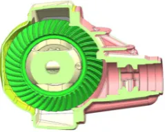
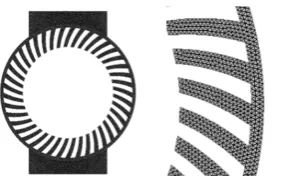
[image:3.595.207.540.175.348.2]In order to reduce the number of cells and save time, it’s necessary to simplify the geometrical model of the hypoid gear (Figure 1). The whole model has been discretized with tetrahedral mesh (Figure 2). During the simulation, the meshes of the hypoid gear rotates in the closed domain at the predefined rotational speed.
[image:3.595.314.434.541.637.2]Table 1 shows the combinations of specific parameters for each simulation. These are respectively simulated at 100 rpm, 400 rpm and 700 rpm, and h represents height of a tooth. Table 2 shows the kinematic viscosity correspond-ing to each oil type. These are all GL-5 type at 40˚C.
Figure 1. Geometrical model of the hypoid gear.
Table 1. Specific parameters of each simulation at the different ratational speed.
Oil type 75W80 75W90 85W90 85W140
[image:3.595.207.543.689.731.2]DOI: 10.4236/jamp.2018.69166 1954 Journal of Applied Mathematics and Physics
[image:4.595.207.541.207.241.2]Figure 2. Grid model of the hypoid gear.
Table 2. Viscosity corresponding to oil type.
Oil type 75W80 75W90 85W90 85W140
Kinematic viscosity at 40˚C (m2/s) 59.07 82.88 248 284.3
4. Results and Discussion
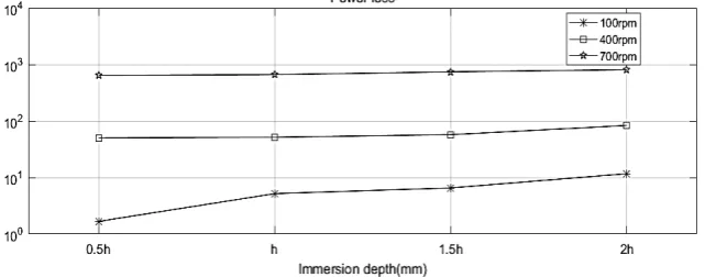
Figure 3 shows that the power loss increases with the immersion depth. De-creasing the immersion depth from 2.0 h to 1.5 h, the power increases about on-ly 50 watts under the same speed. The relation between the immersion depth and the power loss is relatively weak. Figure 4 shows the effect of the viscosity on the power loss. While the viscosity increases from 59.07 mm2/s to 82.88 m2/s, the power loss increases 8.4 watts at 100 rpm, 21.4 watts at 400 rpm and 991.8 watts at 700 rpm. These results show that the rotational speed has impact on ef-fect extent of the viscosity on churning losses. Furthermore, oil type named GL-5 75W80 have minimum effect on power loss. The diagrams show the im-pact of the rotational speed on power loss. It can be clearly seen that the power approximately enhances with 90% while the rotational speed is reduced by 300 rpm. Therefore, the rotational speed has the greatest influence on the churning loss. Figure 5 shows contours of volume fraction for the oil distribution at the different rotational speed. The gear churns more oil with high speed, which re-sults in easily generating larger churning torque. This explains the influence of rotational speed on power loss is maximum.
5. Conclusions
Based on two-phase flow, the VOF method and the standard k-ε model, a new simplified 2D model is established. The oil distributions and the churning power losses of the hypoid gear at the different working conditions with the rotational speed of 100 rpm, 400 rpm and 700 rmp at the immersion depth from 0.5 h to 2 h were numerically investigated.
DOI: 10.4236/jamp.2018.69166 1955 Journal of Applied Mathematics and Physics Figure 3.The effect of the immersion depth on power loss at three different rotational speed.
Figure 4. The effect of the viscosity on the power loss at three different rotational speed.
(a) (b) (c)
Figure 5.(a) Contours of volume fraction for the oil phase at 100 rpm; (b) Contours of volume fraction for the oil phase at 400 rpm; (c) Contours of volume fraction for the oil phase at 700 rpm.
However, the lower speed and the viscosity as well as the immersion depth have influence on gear lubrication and meshing. Thus, the meshing loss of gear transmission system and the impact of lubrication on power loss will be investi-gated in further studies.
Acknowledgements
DOI: 10.4236/jamp.2018.69166 1956 Journal of Applied Mathematics and Physics
Conflicts of Interest
The authors declare no conflicts of interest regarding the publication of this pa-per.
References
[1] Concli, F. and Gorla, C. (2011) Computational and Experimental Analysis of the Churning Power Losses in an Industrial Planetary Speed Reducers. Proceedings of the 9th International Conference on Advances in Fluid Mechanics, Split, 26-28 June 2012, 287-298.
[2] Concli, F., Gorla, C., Della Torre A. and Montenegro, G. (2015) Churning Power Losses of Ordinary Gears: A New Approach Based on the Internal Fluid Dynamics Simulations. Lubrication Science, 27, 313-326. https://doi.org/10.1002/ls.1280
[3] Kodela, C., Kraetschmer, M. and Basa, S. (2015) Churning Loss Estimation for Ma-nual Transmission Gear Box Using CFD. SAE International Journal of Passenger Cars-Mechanical Systems, 8.
[4] Liu, H., Jurkschat, T., Lohner, T. and Stahl, K. (2017) Determination of Oil Distri-bution and Churning Power Loss of Gearboxes by Finite Volume CFD Method. Tribology International, 109, 346-354. https://doi.org/10.1016/j.triboint.2016.12.042
[5] Wang, B., Liu, L.J. and Wang, P. (2014) Simulation of Churning Losses in Geared Box. Applied Mechanics and Materials, 703, 241-244.
https://doi.org/10.4028/www.scientific.net/AMM.703.241
[6] Concli, F. and Gorla, C. (2013) Influence of Lubricant Temperature, Lubricant Level and Rotational Speed on the Churning Power Loss in an Industrial Planetary Speed Reducer: Computational and Experimental Study. International Journal of Compu-tational Methods and Experimental Measurements, 1, 353-366.
https://doi.org/10.2495/CMEM-V1-N4-353-366
[7] Gao, D., Morley, N.B. and Dhir, V. (2003) Numerical Simulation of Wavy Falling Film Flow Using VOF Method. Journal of Computational Physics, 192, 624-642.
https://doi.org/10.1016/j.jcp.2003.07.013
[8] Theodorakakos, A. and Bergeles, G. (2004) Simulation of Sharp Gas-Liquid Inter-face Using VOF Method and Adaptive Grid Local Refinement around the InterInter-face. International Journal for Numerical Methods in Fluids, 45, 421-439.
https://doi.org/10.1002/fld.706
[9] Hou, Q. and Zou, Z. (2006) Comparison between Standard and Renormalization Group k-.EPSILON. Models in Numerical Simulation of Swirling Flow Tundish. Isij International, 45, 325-330. https://doi.org/10.2355/isijinternational.45.325