S200 Position Node with CANOpen/
DeviceNet
Installation Manual
M-SS-S2-11
Revision J June 25 2007
Keep all product manuals as a product component during the life span of the servo amplifier. Pass all product manuals to future users/owners of the servo amplifier.
NOTICE:
1.) This S200 Option requires the use of special user interface software called S200 OC Tools. This software can be installed using the included CD ROM. This device will not communicate with the standard S200 Tools software.
2.) Common Problems
a.) If all dip switches are set to ON (Toggled to the right), the unit enters a perpetual rest state and does not communicate. Change dip switch settings.
b.) When selecting a non-SFD motor, be certain to enter the ‘motor poles’ data. c.) Always remember to Save the configuration to Non-volatile memory.
Record of Revisions
Date Issue Description
2/1/07 D Revised Input definitions
2/19/07 E Major rewrite
4/4/07 F Added Modbus information
5/21/07 G Made clarifications in Modbus Section
6/13/07 H Added Page Numbers, modified encoder input circuit
6/25/07 J Corrected J12 pin-out information
©2006 Danaher Motion - All rights reserved. Printed in the USA.
NOTICE:
Danaher Motion
®is a registered trademark of the Danaher Corporation. Danaher Motion makes every
attempt to ensure accuracy and reliability of the specifications in this publication. Specifications are
subject to change without notice. Danaher Motion provides this information "AS IS" and disclaims all
warranties, express or implied, including, but not limited to, implied warranties of merchantability and
fitness for a particular purpose. It is the responsibility of the product user to determine the suitability of
this product for a specific application.
Safety Symbols
WARNING
Warnings alert users to potential physical danger or harm. Failure to follow warning
notices could result in personal injury or death.
CAUTION
Cautions
personal injury and/or equipment damage.
direct attention to general precautions which, if not followed, could result in
NOTE
Notes highlight information critical to your understanding or use of the product.
Safety
WARNING
READ these instructions before connecting power. Damage can result from MISWIRING at the
power terminals.
DANGEROUS voltages are present on power input and motor output terminals.
Only qualified personnel are permitted to transport, assemble, commission, and maintain this equipment. Properly qualified personnel are persons who are familiar with the transport, assembly, installation, commissioning and operation of motors, and who have the appropriate qualifications for their jobs.
Read all available documentation before assembling and using. Incorrect handling of products described in this manual can result in injury and damage to people and/or machinery. Strictly adhere to the technical information regarding installation requirements.
Keep all covers and cabinet doors shut during operation.
Be aware that during operation, the product has electrically charged components and hot surfaces. Control and power cables can carry a high voltage, even when the motor is not rotating.
Never disconnect or connect the product while the power source is energized.
After removing the power source from the equipment, wait at least 5 minutes before touching or
Danaher Motion 07/06 Table of Contents
Table of Contents
Table of Contents ... i
1
Product Overview ... 1
1.1
Highlights ... 1
1.2
Increased Machine Throughput & Longer Life ... 3
1.3
Reduced Engineering & Support Time ... 3
1.4
CE- / UL- Conformity... 3
1.5
Model Number Scheme ... 3
1.5.1 Valid Drive Model Numbers ... 4
1.6
Specifications... 5
1.6.1 Drive Family Power ... 5
1.6.2 AC Input Drives - Control and Power ... 7
1.6.3 DC Input Drives - Control and Power ... 8
1.6.4 Velocity Loop... 10
1.6.5 Mechanical... 10
1.6.6 I/O Specifications ... 11
1.6.7 Environmental ... 12
1.6.8 Smart Feedback Device (SFD) ... 12
1.6.9 Emulated Encoder Output Signals ... 12
1.6.10 Current Loop ... 12
1.6.11 General ... 13
2
Getting Started ... 14
2.1
Unpacking and Inspecting... 14
2.2
Mounting... 14
2.2.1 Dimensions ... 15
2.2.2 Mounting Outline... 16
2.3
S200 Position Node AC Drive Wiring Diagram ... 17
2.4
S200 Position Node DC Drive Wiring Diagram ... 18
2.5
Connectors ... 19
2.5.1 J1 – AC Input Power Models Drive Power ... 19
2.5.2 J1 – DC Input Power Models Drive Power Connector... 22
2.5.3 DC Input Power Model Power Supply Requirements... 25
2.5.4 Control Voltage ... 26
2.5.5 Grounding ... 26
2.5.6 Bus Capacitance... 27
2.5.7 Bus Switching and Fusing... 28
2.6
J2 – Motor Power Connector ... 28
2.7
J3 – Feedback Connector... 29
2.8
J4 – Command I/O Connector ... 31
2.8.1 Base Drive Unit General Purpose Inputs ... 32
2.8.2 Base Drive Unit Outputs... 37
2.8.3 SFD BAT+... 39
2.8.4 DAC Monitors... 39
2.8.5 Encoder Outputs ... 39
2.8.6 J11 ... 40
2.8.7 J12 ... 42
Table of Contents 07/06 Danaher Motion
2.8.10 LED2...46
3
Operational Notes ...47
3.1
Encoder Input Channels ...47
3.2
Pulse (Step) and Direction...48
3.3
Digital Input Notes ...48
3.4
Ramp Control ...49
3.5
Homing ...50
3.6
Saving Drive Settings ...50
3.7
Configuring Drive from Existing File ...51
3.8
Upgrading Firmware Procedure...52
4
Faults and Errors...54
4.1
CAN Bus Status Indicator...54
4.2
Normal indicator operation ...54
4.3
Clearing Fault Conditions ...55
4.4
Conditional Settings...55
4.5
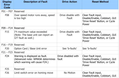
S200 Position Controller Faults ...55
4.6
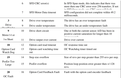
Extended Fault Information ...56
4.7
S200 Base Unit Faults (b-faults)...58
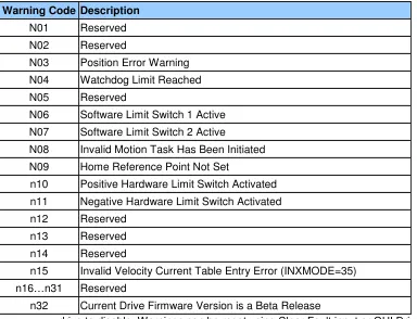
4.8
System Warnings ...59
5
Setup Software...60
6
System Tools ...68
6.1
Status Screen...68
6.2
Communication Wizard ...69
6.3
Variable Editor...69
6.4
Digital Oscilloscope ...70
6.5
Configuration Summary Screen...71
7
Serial Communications and Modbus RTU ...72
7.1
General information ...72
7.2
Abbreviations...72
7.3
RS232 Serial Port Configuration...73
7.4
Exception Messages ...73
7.5
Communication Strategy ...74
7.6
ModBus functions...75
7.6.1 Reading Variables ...75
7.6.2 Writing Variables...76
7.6.3 Example: Read the ACC parameter ...77
7.6.4 Example: Write the ACC parameter...77
7.6.5 Example: Change Speeds in Digital Velocity Mode ...78
7.7
Manufacturer specific function Codes...79
7.7.1 Command functions...79
7.7.2 Command Execution: FC 65...79
7.7.3 Command execution status ...80
7.7.4 Drive Status ...80
7.7.5 Set Motion Task...81
7.7.6 Clear All Motion Tasks...82
7.8
Mobus Address and function Tables ...82
Appendix A - Cables ...89
Table of Contents 07/06 Danaher Motion
B.3 CE EMC Compliance... 91
B.3.1. CE Test Setup... 92
B.3.2 CE Test Setup ... 93
B.4 Declaration of Conformity... 94
B.5 Installation and Commissioning ... 96
B.6 Safety requirements... 96
B.7 European Compliance ... 96
B.9 UL and cUL Conformance ... 98
B.10 Additional Safety Precautions ... 98
B.9 EMC Compliance with EN61800-3 ... 99
B.10 AC Mains Conducted Emissions... 100
B.11 Regen Resistor ... 102
B.12 Additional EMC Information Sources ... 102
1
PRODUCT OVERVIEW
The S200 Position Node with CANOpen/DeviceNetTM brings greater flexibility to the S200 drive platform by adding profile generation and field bus
capabilities. It also brings added I/O, Digital Oscilloscope emulation, and the ability to use incremental encoder with commutation tracks (ComCoder) for motor feedback.
The S200 Position Node brushless position node servo drives with CANOpen push high performance servo technology into lower power applications than was previously possible without having to compromise on reliability or package size. Couple a S200 position node drive with an AKM servo motor for a
complete servo control solution designed to excel in applications such as semiconductor fabrication, electronic assembly, packaging, medical, and woodworking equipment.
The S200 position node servo drives with CANOpen communication are the first all digital industrial drives with a velocity loop bandwidth up to 800 Hz offering unmatched system throughput and simplified tuning. High resolution (24 bit) feedback and high performance 3-5 kHz current loop bandwidth provide smooth motion and rapid start and stop action to optimize machine performance. Smart feedback and industry leading high bandwidth deliver fast and accurate commissioning by eliminating the need for servo loop tuning in most applications.
A separate "keep alive" power input allows rapid recovery from emergency stop conditions. Optically isolated inputs/outputs, positive locking connectors and full fault protection promise long machine life and immunity to accidental damage. A single motor power/feedback cable simplifies connectivity. All connectors and LED status indicators are easily accessible from the front of the drive.
1.1
H
IGHLIGHTS
DC or AC input voltage:
DC type: 20 V ... 90 V
AC type: 110 V ... 240 V, 1Ø or 3Ø, 50/60 Hz
Highest performance all digital servo in the industry
Operation and Setup via a PC using the S200 OC Tools setup software
Easy set up and tuning with Smart Feedback Device
Optimized performance with AKM motors
Rugged optically isolated I/O
UL508C recognition, CE (EN50178, EN61800-3)
Very compact footprint
Full fault protection
Velocity, Position, and Electronic Gearing control standard
Indexing - 180 unique motion tasks can be defined and initiated via the serial port
or discrete inputs
Relative, Absolute, Simple Registration, and Home motion tasks can be easily
setup and executed
1.2
I
NCREASED
M
ACHINE
T
HROUGHPUT
& L
ONGER
L
IFE
Servo system performance is synonymous with machine throughput. The S200 POSITION NODE family takes servo performance to new heights.Industry-leading current loop bandwidth up to 5 kHz and velocity loop
bandwidth up to 800 Hz means machine throughput can be increased by as
much as 2 to 3 times.
Robust design including full fault protection, locking connectors and optical
isolation promise greater machine “up-time”.
Smooth motion, a benefit of sinusoidal current control and high resolution (24
bit) feedback minimizes harsh torque disturbances that can cut short the life
of mechanical components.
Both the AC and the DC input drives are equipped with separate control
power input to speed recovery from “E-Stop” conditions.
CANOpen Field Bus or DeviceNet communications
1.3
R
EDUCED
E
NGINEERING
& S
UPPORT
T
IME
Simplified tuning, friendly Graphical User Interface and shared components with Stepper products.
Windows-based Graphical User Interface models the tree format found in Explorer so
learning is quick and easy.
Digital Oscilloscope emulator for easier setup.
Easy to debug with full fault diagnostics reduce engineering support time.
Field bus connectivity.
1.4
CE- / UL- C
ONFORMITY
The S200 position node with CANOpen meets all relevant standards:
EMC Directive 89/336/EWG, standard used ENG61800-3
Low Voltage Directive 73/23/EWG, standard used 50178
UL / cUL 508C recognized
1.5
M
ODEL
N
UMBER
S
CHEME
S2 03 3 0 CN S - 002
Family
S2 - S200 Servo Family
Current Rating 02 - 1.5 ARMS continuous, 4.5 ARMS peak
03 - 3 ARMS continuous, 9 ARMS peak
06 - 6 ARMS continuous, 18 ARMS peak
Voltage 3 - 20-90 VDC
5 - 120 VAC doubler/240 VAC 1-phase
6 - 120/240 VAC
Customization - omit for standard drives 000 - 019 Reserved for factory use only
020 - 999 Reserved for customers only
Feedback Support S - SFD/Halls - Base Unit
SFD/Comcoder - CAN option card
Smart Feedback Device (SFD) - SynqNet Option Card Sine encoder - SynqNet Option Card
EnDat 2.1 - SynqNet Option Card
Functionality
VT - Velocity/Torque modes
CN - Position Node w/CANOpen Interface
SD- SynqNet option card w/ micro-D connectors
SR-SynqNet option card w/ standard RJ connectors
Electrical Option 0 - No Electrical Option
1.5.1
Valid Drive Model Numbers
DC Input Power Drive Models
S20330-VTS: 90 VDC, 3/9 ARMS Base Unit S20630-VTS: 90 VDC, 6,18 ARMS Base Unit
S20330-CNS: 90 VDC, 3/9 ARMS Base Unit, CAN/Indexer option card S20630-CNS: 90 VDC, 6/18 ARMS Base Unit, CAN/Indexer option card S20330-SRS: 90 VDC, 3/9 ARMS Base Unit, SynqNet option card with RJ-45 connectors
S20630-SRS: 90 VDC, 6/18 ARMS Base Unit, SynqNet option card with RJ-45 connectors
S20330-CNS: 90 VDC, 3/9 ARMS Base Unit, SynqNet with Micro-D connectors S20630-SDS: 90 VDC, 6/18 ARMS Base Unit, SynqNet with Micro-D connectors
AC Input Power Drive Models
S20250-CNS: 120VAC doubler/240VAC, 1 phase, 1.5/4.5 ARMS Base Unit, Profile Node with CanOpen
S20250-DNS: 120VAC doubler/240VAC, 1 phase, 1.5/4.5 ARMS Base Unit, Profile Node with DeviceNet
S20260-CNS: 120/240 VAC, 1/3-phase, 1.5/4.5 ARMS Base Unit, Profile Node with CanOpen
S20260-DNS: 120/240 VAC, 1/3-phase, 1.5/4.5 ARMS Base Unit, Profile Node with DeviceNet
S20350-CNS: 120VAC doubler/240VAC, 1 phase, 3/9 ARMS Base Unit, Profile Node with CanOpen
S20350-DNS: 120VAC doubler/240VAC, 1 phase, 3/9 ARMS Base Unit, Profile Node with DeviceNet
S20360-CNS: 120/240 VAC, 1/3-phase, 3/9 ARMS Base Unit, Profile Node with CanOpen
S20360-DNS: 120/240 VAC, 1/3-phase, 3/9 ARMS Base Unit, Profile Node with DeviceNet
S20650-VTS: 120VAC doubler/240VAC, 1/3-phase 6/18 ARMS Base Unit S20650-SRS: 120VAC doubler/240VAC, 6/18 ARMS Base Unit, SynqNet option
card with RJ-45 connectors
S20650-SDS: 120VAC doubler/240VAC, 6/18 ARMS Base Unit, SynqNet with Micro-D connectors
S20650-CNS: 120VAC doubler/240VAC, 6/18 ARMS Base Unit, Profile Node with CanOpen
S20650-DNS: 120VAC doubler/240VAC, 6/18 ARMS Base Unit, Profile Node with DeviceNet
S20660-VTS: 120/240 VAC, 1/3-phase 6/18 ARMS Base Unit
S20660-SRS: 120/240 VAC, 1/3-phase 6/18 ARMS Base Unit, SynqNet option card with RJ-45 connectors
S20660-SDS: 120/240 VAC, 1/3-phase 6/18 ARMS Base Unit, SynqNet with Micro-D connectors
1.6
S
PECIFICATIONS
NOTE
Unless otherwise specified, the specifications are worse case
limits and apply over the specified operating ambient
temperature and over the specified operating line voltage.
1.6.1
Drive Family Power
!
! "
# #
! !
! $ $ % & # ' '
! $ $ % & " ! ' '
" $( $ ' ' ' "
! $ % )& * # ! ' '
! $ % )& * ' '
! $ % )& * ! ' ' '
" $( * ' ' ' !
! " #$ % & '
* "
* ! ! !
(
! $ )& ! " ' '
! $ )& # ! ' '
! $ )& # ! ' '
)$* %
+,-+ ( ' ' ' # "
, - ) . )/ 0 ' ' ' ! " !
. / " " ! # !
0 #
) .)* .1 #2 # ! 2 2 ' '
)* * #2 # ! 2 2 ' '
3 - (-4 45 6 #2 ! 2 2 ' '
$ 5- 2 ! 7 ! 7 ! 7 ' '
$ 1 1 2 03 4 5 #
$( 8 59: ! ' '
" $( 9: * & % ;
+5 $(
' ' '
#6 7! 89 ! ! ! ! !
: 1 1 #;# 8 ! ! ' '
< : 1 1 #;# 8 "
< 4# ( 0 .
1< 5 !
1< 5
1 Peak Output Current listed is for sine mode. In six-step mode, the peak output currents are scaled to give the
same output torque as in sine mode with a pure sinusoidal Back EMF motor. To convert ARMS to A(0-pk), multiply ARMS * 1.414.
2 For Operation above Above 40o C ambient: Derate linearly to 67% at 50o C .
At higher ambient temperatures (above 30o C) the S20360 drive needs to be mounted on a thermally conductive
surface to limit the heatsink temperature to less than 75o C.
3 Single phase operation of the S20660 requires derating of continuous output power to avoid excessive AC line
front-end currents.
1.6.2
AC Input Drives - Control and Power
#
#
3
- # 0 0
$ !# $ 5 &
" # =>
! $( " $(
: 0 ! (
$ # =>? " # => 45
! $ # =>? # => 45
! $ # =>? # => 45
#
3
- # 0 0 - !#
! 00 :=- !
< ( =- &
1Maximum AC Line is specified to limit the mains surges to the drive.
$
- # 0
:6 #
. - " #$ - # 0 ! $(
& - " #$ - # 0 $(
$* * : # 0 6 # @ 4( -5 8
$* #0 $ - 6 # " $( A 6
$* 0 - # 0 B " C9-D$ B " $( 8 5
>6
0
? . - '
# :
1 : :6 0(
3 % , - #36
! $ )& 9- ( ' 9- ( ' 9- ( '
! $ )& 9- ( ' 9- ( '
! $ )& 9- ( ' 9- ( ' 9- ( '
#
>6
0
? 1 . - '
# : #
6 0% # 9- ( 7 E!
#3
1.6.3
DC Input Drives - Control and Power
#
5$ 5 $(
F' F'! A A
5, - * * !
1(20 watt min supply recommended) Refer to the DC Power Supply Section for detailed application information and requirements.
$* - # 0
:6 #
A9: $ 5 $( F' F'! A! A
A9: : +5 @-5 A " $( 5
A9: D+ +5 @-5 A $( 5
#3
5) * 5 ( + D 5
#
)& - 1 +
, 3' - - G- B
0HC( + ,@9
)- - 5 3' %
. +
! 7 0 0 0 1
) . & *
-5 540H 4 # 5 * 0
)
0H 8' E C( + , .
, - 0H 8' E C,@9
(
$ : :
< $ : :
, - ( + .=>
( , - ( + .=>
1 : :$ : :
, - ( + .=> !
( , - ( + .=>
@( - .=> I( !
9 * &$ @ @3 J
6 -5 - +5
K!
: ) ;
1 : : < 2#1 1 #6 7 13 89
, - ( + => #
!
!
3 1 # ?
!6 E ! 6 E#
!6 E! 6 E#
!6 E! 6 E#
1.6.4
Velocity Loop
3 - 59 * & =>* & @(
: ) ;
%
5- L 5
5
- #1 3(
0$) ( , . # , . E E
0$) 5- 6
0$, => ?!!
0$, 5- 6
@ => ! ? ##!"
@ => ! ? ##!"
1Values for ARF0, ARF1; from 3012 to 24873 Hz cannot be set.
1.6.5
Mechanical
" * -2
" * -2
;-;@@ ;@@ ;@@ ;-;@@ ;@@
( + = & !
# ! # " # " # " #
( + 1 & 9 ! " #
! ! ! # ! #
( + ( &
" "
# # #
0
8 : M M
M M M ? 0 . 5 . 5 ! . 5 " * &
"" . # 5
. # 5
1 Depth measurement is for drive only. Add approximately 50.8 mm (2 in) to depth given in the table
1.6.6
I/O Specifications
Analog command is not allowed in this product. Digital Velocity and Motion Task position loop control is the only possibilities.
#0
1
"&A
"
B
. &.A
&,
3 - +5 7
@-55 5H 5 6
H4 51 AE' K
J 4 6 @-55 5 L
L!' #@-55 5
D $ L
D ( ;$E 4 !
C
:
C : 8 B& ;& A& 8$ B& ;&.A&,
H4 ' !!E '
, - $ 5 3 ND 55 %HHJ%( 5
5
, - H 3
3 - J @ G- 4 #! .=> ! =>G- - -5
D
#
0 #
" &;.A " ;E B. ;. :B& ;,
, - $ 5
(,8) D F'
K ' +5
, - - # ' # "
H
" ,F " &
8 " ; B.;& >&&AB& G>E, - $ 5 7 # +5
, - - 7 !
D
#
* &A * B.; A+ :B.;GAE
3 - D- - $ 5 ' +5
5 $ 5 +5K#6
3 D
-D +5 +5
! +5 H
C
:
C : 8 ; B.;&EA 8$; B.; &A 8H; B.;&+A&G
H4 ' !!E '
D- - $ 5 $ ( 5D- - ' : 5
-1.6.7
Environmental
D H - 7 @-55
D H - 7 (
J 54( -- - #"6 7
) 55- ( !
H - '! "
=- 4 6 '
5 - L
1.6.8
Smart Feedback Device (SFD)
5- E + ! B
54 LK!' +BK
"
8 @5 L!' " + B #
=> 5) 5@5 L!' + B
=> 5) 5@5 L!' + B !
!! ! L!' +E B E
4 # 11 13
0 K!' +BK "
0 ! % K!' +BK
- : ) ; !
1.6.9
Emulated Encoder Output Signals
#4#
#
9
4
! % !% ! %!
%
#%
!% #
% !"#
(
5
! %
%
%!
%!
%
%
%!
3 - D- - J
@ G-
4 =>
!
3
!"# ))
!!
3
#
))
#
3
# ))
. )-5 1
&
P O-
- )-5
1.6.10
Current Loop
1.6.11
General
3H . ? #
3 !
3H . 5 E ? #3 #
2
GETTING STARTED
2.1
U
NPACKING AND
I
NSPECTING
Open the box and remove all the contents. Check to ensure there
is no visible damage to any of the equipment.
CAUTION
Use proper procedures when handling electronic
components to avoid damage to equipment.
CAUTION
Remove all packing material and equipment from
the shipping container. Be aware that some
connector kits and other equipment pieces may
be quite small and can be accidentally discarded.
Do not dispose of shipping materials until the
packing list has been checked.
NOTE
Upon receipt of the equipment, inspect
components to ensure that no damage has
occurred in shipment. If damage is detected,
notify the carrier immediately. Check all shipping
material for connector kits, documentation,
diskettes, CD-ROM, or other small pieces of
equipment.
2.2
M
OUNTING
The S200 drives are designed for operation in a cabinet using the following installation instructions:
Mount the drives vertically inside a cabinet on a flat, solid, electrically conductive, mounting surface connected to PE (protective earth ground) and capable of supporting the weight of the unit.
Provide a good connection to PE. Remove the paint on the mounting surface over an area extending at least 12 mm (0.5 in) from the mounting bolts to achieve good electrical connection over a large area between the drive and grounded mounting surface.
2.2.1
Dimensions
" *
-2 " * -2
( + = & !
#
" #
" #
( + 1 & 9 #
! ! ! #
( + ( &&
"
# #
# 1 7
H 9 ( ! " ! !
/ ! " ! !
0
= > 5 - D @ ! #
"
! # ! #
$ 5 - D <
# " "
$ 5 - = & =
#
# # #"
# # #"
( + ( + - F # #
!
"
# #
08 : M M M
? 0 .
5
. 5
. # 5
2.2.2
Mounting Outline
DEPTH (C)
WIDTH (B)
REAR VIEW RIGHT SIDE VIEW
FRONT VIEW
HEIGHT (A)
VERTICAL MOUNTING HEIGHT (H)
VERTICAL MOUNTING OFFSET (G) VERTICAL MOUNTING OFFSET (G) HORIZONTAL MOUNTING OFFSET (F) TOP VIEW
RECOMMENDED MOUNTING HARDWARE M4 OR #8
0.18 mm 4.57 in
F
0.18 mm2.3
S200 P
OSITION
N
ODE
AC D
RIVE
W
IRING
D
IAGRAM
DINP1 DINP2 DINP3 DINP4
DOUT 1
DOUT 1 +
DOUT 2
DOUT 2 + DINP5 + DINP5 -NC
DAC MON 1
CH Z OUT
DAC MON 2
CH Z OUT CH A OUT CH A OUT CH B OUT CH B OUT
ANA CMD + ANA CMD
-1 2 3 4 5 6 7 8 9 10 11 14 15 16 12 13 17 18 19 20 21 22 23 24 25 26 DINP COM DINP6 DINP7 DINP8 DINP9 DOUT 3 + DOUT 3 DINP 10+ DINP10 -5V Source 1 2 3 4 5 6 7 8 9 10 11 14 12 13 CH A / Step
CH A / Step
CH B / DIR
CH B / DIR DINP COM 5V COM I/O RET I/O RET I/O RET I/O RET 15 SFD 1 2 3 6 4 5 MOTOR PE U V W 1 2 3 4 1 2
3
4 51
2
3
6
4
5
120/240VAC Mains
47-63Hz Fused
120/240VAC Control
Power 47-63Hz Fused
Protective Earth Optional Regen Resistor 1 2 3 4 5 6 7 8 9 NC Tx Data RX Data I/O RET I/O RET NC NC CAN H CAN L V+ V-SHIELD J4 J3 J2 J1 J12 J11 J5 RS 232 Configuration Port 1 2 3 4 5 6 7 8 9 10 11 14 12 13 15 J13
S200 Drive
AC Input Power
Models
CU CV CW I/O RET I/O RETCH Z IN
CH Z IN
PTC
PTC RET 5V SOURCE
CH A IN
CH A IN
CH B IN
CH B IN
2.4
S200 P
OSITION
N
ODE
DC D
RIVE
W
IRING
D
IAGRAM
DINP DINP DINP DINP DOUT 1 DOUT 1 DOUT 2 DOUT 2 DINP5 DINP5 -NCDAC MON 1
CH Z OUT DAC MON 2
CH Z OUT CH A OUT CH A OUT CH B OUT CH B OUT
ANA CMD ANA CMD
-1
2
3
4
5
6
7
8
9
10
11
14
15
16
12
13
17
18
19
20
21
22
23
24
25
26
DINP DINP DINP DINP DINP DOUT 3 DOUT 3 DINP DINP10 -5V Source1
2
3
4
5
6
7
8
9
10
11
14
12
13
CH A / StepCH A / Step CH B / DIR CH B / DIR DINP 5V COM I/O RET I/O RET I/O RET I/O RET
15
SFD
1
2
3
6
4
5
MOTOR
PE U V W1
2
3
4
1
2
3
1
2
3
6
4
5
Main Power
20 – 90 V
DC1
2
3
Tx Data RX Data I/O RET I/O RET NC CAN H V+ SHIELD J4 J3 J2 J1 J12 J11 J5 Optional CAN Bus Connection RS 232 Configuration Port1
2
3
4
5
6
7
8
9
10
11
14
12
13
15
J13S200 Drive
DC Input Power
Models
CU CV CW I/O RET I/O RET CH Z IN CH Z IN PTC PTC RET5V SOURCE
CH A IN CH A IN CH B IN CH B IN
Optional Encoder Feedback PE W V U +5V 5V RET SFD COM -SFD COM+
+ CNTL
+ BUS BUS/CNTL GND
Note: J1 Pin 2 and all I/O RET pins are tied together within the drive.
2.5
C
ONNECTORS
2.5.1
J1 – AC Input Power Models Drive Power
The S200 AC input drives are capable of direct line operation. All
units are fully isolated and do not require external isolation
transformers. The inrush current on the connection to the line is
internally limited to a safe level for the drive. There are no voltage
selection or ranging switches required to operate within the specified
voltage input ranges.
The S200 series drives are functionally compatible with all standard
forms of three phase AC lines:
Grounded neutral WYE
Open-Delta Grounded Leg
TEE
NOTE
It is the customer’s responsibility to supply appropriate
fuses or circuit breakers in the J1 AC drive power lines to
comply with local electrical codes.
The control input power required is between 5 and 10 watts. The AC
motor input power depends on output power and losses in the power
stage.
On AC input drives, J1 is a 9-pin plugable connector.
1 9
(J1 Connector view from front of drive).
Pin Description
J1-1 PE (Protective Earth) – Must be tied back to central earth bar.
J1-2 REGEN - Model S20660 uses a 26 resistor. For all other models, the chosen resistor must be rated for the appropriate peak power (400 V ^2 / x
). For example, 25 to 50 for the S20260 and 20360 drives or 15 to 50 for the S20630 and S20330.
J1-3 -BUS DC – Internal DC Bus negative connection (Not normally used) J1-4 +BUS – Internal DC Bus Positive Connection (Regen Resitor Termination
J1-5 C2 CTRL VAC – Logic control Power J1-6 C1 CTRL VAC – Logic Control Power J1-7 L3 240 VAC – Main Line
J1 Mating Connector Information Screw Terminal Connector:
12 – 24 AWG Wire Range, Phoenix MSTB2,5/9-STF-5,08-BK OR Spring Cage Clamp Connector
12 – 24 AWG Wire Range, Phoenix FKC 2,5/9-SFT-5,08-BK OR Crimp Connector
14-20 AWG Wire Range, Phoenix MSTBC 2,5/9-STZF-5,08-BK Crimp Contact: 14-16 AWG Wire Range, Phoenix MSTBC-MT 1,5-2,5 Crimp Contact: 18-20 AWG Wire Range, Phoenix MSTBC-MT 0,5-1,0
Refer to
www.phoenixcon.com
.
J1-1 PE Protective Earth
Protective Earth: This chassis ground point must be connected to
Protective Earth ground. The connection at the Protective Earth ground end must be hard wired (do not use a plugable connection). A ground fault detector (RCD) cannot be depended on for safety.
J1-2
REGEN Connection for an optional regeneration power resistor to absorb regenerated energy from the motor. Models S20260, S20360 use 36 . Use a Wire wound resistor with 1500 VRMS isolation between terminals and case. Many
applications do not require a regen resistor. If over-voltage faults occur during motor deceleration, connect the proper ohm 50 to 300 watt power resistor from this terminal to terminal J1-4 (+BUS). The power rating of the regen resistor depends on the amount of regenerated energy that needs to be dissipated.
WARNING
The Regen input is not short circuit protected. The Regen Resistance MUST be within specified ranges to prevent damage to the drive. For example, between 25 to 50 for the S20260, S20360 drives or 15 to 50 for the S20660.
NO TE
For safety, either mount the external resistor on a grounded panel or wire it to a grounded connection. The terminals of the resistor MUST NOT be grounded.
WARNING
Wait 5 minutes after power is removed for the bus cap voltage to decay to a safe level before touching the regen resistor or wiring. Monitor the voltage on the bus caps with a voltmeter from +BUS (J1-4) to -BUS (J1-3).
J1-3
-BUS The -BUS terminal is usually left open during normal operation. In special multi-axis applications drive buses can be wired in parallel to allow returned energy from one motor to power another and limit high regen powers.
J1-4
+BUS The +BUS terminal is used with the J1-2, REGEN, terminal to add a regen resistor to the drive to absorb regenerated energy.
CAUTION
NOTE
After powering down the drive, monitor the BUS voltage by connecting a meter from J1-4 (+BUS) to J1-3 (-BUS) to verify the internal BUS capacitors have discharged prior to working on the drive.
J1-5, J1-6 C2 CTRL VAC C1 CTRL VAC
These terminals connect 120/240 VAC power to the drive’s control voltage power supply.
- # 0 0 $ !# $ 5 &
" # =>
! $( " $(
' * &! $ ,
-# : #
6 0 9- ( 7 Q
NOTE
For maximum ride through capability a 240 VAC input is recommended.
J1-7, J1-8, J1-9 L3 240 VAC L2 240/120 VAC L1 240/120 VAC
These terminals connect 120/240 VAC power to the drive’s output power stage BUS.
For single phase operation 120/240 use inputs J1-8, L2, and J1-9, L1.
- # 0 0 !# $
! ! 0$ 7 0$
G-< ( 0$ &
' * &! $
-# :
6 0
! $ )& 9- ( ' 9- ( ' 9- ( '
! $ )& 9- ( ' 9- ( ' 9- ( '
! $ )& 9- ( ' 9- ( ' 9- ( '
1Maximum AC Line is specified to limit the mains surges to the drive.
2.5.2
J1 – DC Input Power Models Drive Power Connector
The S200 DC input drives should be powered from power supplies with reinforced isolation.
1 3
(J1 Connector view from front of drive).
Pin Description
J1-1 +CTRL
J1-2 BUS/CTRL GND J1-3 +BUS
CAUTION
To avoid damage to the connector and drive, NEVER plug or unplug J1 with power applied.
Mating Connector Information Screw Terminal Connector
12 – 24 AWG Wire Range, Phoenix MSTB2,5/3-STF-5,08-BK OR Spring Cage Clamp Connector
12 – 24 AWG Wire Range, Phoenix FKC 2,5/3-SFT-5,08-BK OR Crimp Connector
Crimp Shell: 14-20 AWG Wire Range, Phoenix MSTBC 2,5/3-STZF-5,08-BK
Crimp Contact: 14-16 AWG Wire Range, Phoenix MSTBC-MT 1,5-2,5 Crimp Contact: 18-20 AWG Wire Range, Phoenix MSTBC-MT 0,5-1,0
Refer to
www.phoenixcon.com
.
J1-1
+CTRL Control power input. The DC drive accepts +10 to +90 VDC on this input referenced to J1-2. An isolated regulated or isolated unregulated power supply can be used. This input can be connected to +Bus input, J1-3, and powered by the same supply as +Bus.
The control power supply should be rated for 20 watts. While the power drain typically is 2 W to 8 W, a 20 W supply ensures reliable starting of the drive.
J1-2
BUS/CTRL GND Power return for the control and BUS power supplies. The BUS/CTRL GND is connected to I/O RTN internally in the drive.
J1-3
)$ ! * *
)$ " * % *
NOTE
Refer to the DC Power Supply Requirements section for detailed requirements selecting a compatible power supply.
PE
Screw Connection Protective Earth connection point. This chassis ground point must be connected to Protective Earth ground. The connection at the Protective Earth ground end must be hard wired (do not use a pluggable
2.5.3
DC Input Power Model Power Supply Requirements
$ - # 0 B&; B&; A ! $( A $(
$* #3 .G- $* +,- $*
!
-) .
( # 1
( 1
( ! 1
( " 1
! #
-) .
# " ( ! 1
! ( # 1
# " ( 1
! ( % 1
$* 1 1 .G- $* +,- $*
! % ;%# $ !% ;% $
! # % ;%# $ % ;% $
Bus Supply Characteristics The BUS Supply should have the following characteristics: Must provide safety isolation from the power line Can be regulated or unregulated
Bus Supply Return is connected to the Control Supply Return and I/O RTN in the drive
Typical BUS Supply:
Unregulated, Isolating, step down transformer with secondary rectified into capacitive filter
BUS Supply Return is connected to earth ground
Wiring from BUS Supply to
Drive 10 ft maximum 16 AWG (minimum) Twisted pair
Daisy chaining of multiple drive OK
No contactor or switching in the BUS wiring
Control Voltage
(J1-1 to J1-2) + 10 VDC to +90 VDC
Control Supply Type Isolating
Unregulated or Regulated
Common GND with bus supply and I/O RTN 20 watt supply or 1 amp short circuit
Control Supply Wiring Wire control (J1-1) to bus (J1-3) or
Control Supply Current 20 to 110 mA at 75 VDC 60 to 330 mA at 24 VDC 125 to 660 mA at 12 VDC
Bus Voltage
Bus voltage outside the operating range (20 to 90 V) causes an under-voltage or over-voltage fault. Under-voltage and over-voltage faults self clear when the fault condition clears.NOTE
Do Not allow the Bus Voltage to exceed + 90 VDC. This causes damage to the drive.
Target design center voltage for unregulated supply is +
70 to + 75 VDC. This provides 15 to 20 VDC margin for
line tolerance, transformer regulation, and regen pump
up. Design center voltage for a regulated supply can be
up to + 80 VDC.
2.5.4
Control Voltage
The control voltage range for normal operation is + 10 VDC to + 90 VDC. The control voltage can either be wired to the bus voltage so one supply can power the drive, or from a separate supply. Separately powering the control from the bus allows the bus to be powered down for safety while drive status and fault information remain available. A single + 10 VDC to + 30 VDC supply can be shared by Control and I/O.
NOTE
Do Not allow the Control Voltage to exceed + 90 VDC as it can damage the drive.
2.5.5
Grounding
Provide safety isolation with the external bus and control supplies from the power line.
NOTE
The drive cannot be powered from an electrically Hot supply as it does not contain an isolation barrier.
NOTE
The maximum voltage allowed between Bus/Ctrl Gnd and chassis is 100 VDC.
2.5.6
Bus Capacitance
There is a minimum requirement on the output capacitance of the bus power supply for the DC input S200. This capacitor is needed to absorb energy during motor deceleration and motor disable and to help provide energy during motor acceleration. For multiple S200 drives operated from one supply the
2.5.7
Bus Switching and Fusing
Do not put E-Stop switches or contactors between the drive bus pin (J1-3) and the power supply bus capacitor. There is a risk of damage to the drive if the bus is disconnected from the power supply capacitor when the drive is enabled. The motor does not need to be rotating to regenerate energy. The motor windings store magnetic energy that regenerates back to the supply when the drive is disabled.
E-stop switches can safely be located in series with the primary winding of a step down transformer. If individual axis E-Stop switches are required, connect a local (unswitched) capacitor (1,000 µf, 100 V) across the drive bus terminals (J1-3 to J1-2).
If the buses of individual drives are to be fused, select the fuse type and rating for high margin.
S20630 (6 amp) S20330 (3 amp)
15 A, Slo-Blo (Bussmann
MDA-15) 7 A, Slo-Blo (Bussmann MDA-7)
2.6
J2 – M
OTOR
P
OWER
C
ONNECTOR
J2 is a 4 pin pluggable connector.
1 4 (J2 Connector view from front of drive).
1
F!' )/ & < - ! , - ( +
9: EH J<8( ! ( , - ( +
F!'! )& 1
F!' )& $
F!' )& :
Mating Connector Information
Screw Terminal Connector: 12 – 24 AWG Wire Range, Phoenix MSTB2,5/4-STF-5,08-BK
OR
Spring Cage Clamp Connector: 12 – 24 AWG Wire Range, Phoenix FKC 2,5/4-SFT-5,08-BK
OR
Crimp Connector
Crimp Shell: 14-20 AWG Wire Range, Phoenix MSTBC 2,5/4-STZF-5,08-BK Crimp Contact: 14-16 AWG Wire Range, Phoenix MSTBC-MT 1,5-2,5 Crimp Contact: 18-20 AWG Wire Range, Phoenix MSTBC-MT 0,5-1,0
J2-1 PE Motor Case Ground
On S200 AC Input Drives this point is connected to Chassis Ground.
J2-2, 3, 4 Motor Phases
These three terminals provide the 3-phase power output to the motor.
NOTE
Observe motor polarity, connect phase U on the drive to phase U on the motor, etc.
For nonstandard motor drive combinations consult the factory for proper phase orientation.
2.7
J3 – F
EEDBACK
C
ONNECTOR
J3 is a 6-pin plugable IEEE 1394 style connector for the feedback device. Although this connector mechanically accepts standard IEEE 1394 cables, it is electrically not an IEEE 1394 interface. The base drive accepts either SFD (Smart Feedback Device) or Hall inputs.
1 2 3 4 5 6
(J3 Connector view from front of drive)
Pins
Description
J3-1
SFD +5 V (200 mA)
J3-2
SFD +5 RTN
J3-3
SFD COM-
J3-4
SFD COM+/CU
J3-5
NC/CV
J3-6
NC/CW
Shell
Shield Connection
Mating Connector InformationIEEE1394, Firewire type, 2.0 mm plug set 22 AWG Max., Molex 55100-0600
J3 –1
SFD +5 V This terminal provides a 5 VDC output to power the feedback device. For example, motor equipped with SFD, Halls or commutation encoder. The load current should not exceed 200 mA.
J3-2
SFD +5 RTN This terminal is the return connection for the 5 VDC supply. An inner feedback cable shield can be connected to this point. Outer shields should connect to the shell which is PE.
J3-3
SFD COM- SFD serial communications port when using the SFD feedback device. No connection when using Hall feedback.
J3-4
SFD COM+ / CU
SFD serial communications port when using the SFD feedback device. CU (Commutation Phase U) input when using open collector Hall feedback. This input has a 2.21 kΩ pull-up resistor to 3.3 volts.
J3-5
NC / CV No connection when using the SFD feedback device. CV (Commutation Phase V) input when using open collector Hall feedback. This input has a 2.21 kΩ pull-up resistor to 3.3 volts.
J3-6
NC / CW No connection when using the SFD feedback device. CW (Commutation Phase W) input when using open collector Hall feedback. This input has a 2.21 kΩpull-up resistor to 3.3 volts.
2.8
J4 – C
OMMAND
I/O C
ONNECTOR
J4 is a 26-Position High Density D subminiature female connector.
1 10 19
9 18 26
(J4 Connector view from front of drive.)
Mating Connector Information
26-Pin Male High Density D-Sub with Back shell Kit
24 AWG Max., NorComp 180-026-102-001 – D-Sub Connector NorComp 978-015-010-03-1 – Back shell Kit
Refer to www.norcomp.net.
1 1
F' (,8) D F' ( D8
F'! (,8) / 5 F' ( D8!
F' (,8)! F' # ,ED H8
F' (,8) F' " / D- - & 5R
F' (,) ,8) F' / D- - & 5Z F'# (D:H ' F' & 5 / D
-F'" (D:H A @-5 F'! & 5A / D
-F' (D:H!' F'! & 59/ D
-F' (D:H!A :8 F'!!
& 5B / D
-F' (,8) A = ,8)A F'! ,ED H8
F' (,) 7 = ,8)' F'! 5 , - A
F' ! @( 9 HA F'! 5 , - '
2.8.1
Base Drive Unit General Purpose Inputs
General PurposeInputs DINP1-3 J4-2, 3, 4 DINP4 J4-5
Common Input Terminal J4-1
The general purpose inputs are a bank of four inputs that share a common terminal, DINP COM, on J4-1. The inputs operate over a wide input voltage range of ± 4.0 to ± 30 volts.
General purpose inputs are compatible with either sourcing or sinking currents to provide maximum flexibility for interfacing to field wiring.
Common Rail for Inputs 1 through 4. Common can be tied to positive supply or negative supply, depending on the
application need. J4-1
DINP COM
J4-2 DINP1 (ENABLE)
J4-4 DINP3
J4-5 DINP4/MSINP1
4.32 k 4.64 k
4.32 k 4.64 k
4.32 k 4.64 k
4.32 k 4.64 k J4-3
DINP2
Input current is a function of the input voltage and listed in the following table.
- # 0 I
I
+5
#
+5
! +5
!
! +5
+5
# "
The response time for DINP1, DINP2 and DINP3 is less than 1 ms. MSINP1 has a response time of less than 100 µs.
The list below describes the factory defaults for each of the inputs. A logic input is active when current is flowing through the photo diode. Inactive inputs are open circuited.
Default Input Functions DINP1
(ENABLE) Input 1: This input enables the drive. When input 1 is activated (current flowing in the photo diode), the drive is enabled. This input must be actively driven to enable the drive. An open circuited input disables the drive. DINP2 Input 2: General purpose input default assigned to Home Switch. DINP3 Input 3: General purpose input default assigned to Start Move BCD. DINP4 Input 4: General purpose input default assigned to Move Select Bit. One of
two inputs that can be assigned as end-travel limit switch inputs.
Sinking Logic For compatibility with sinking outputs, the DINP COM terminal is connected to the positive terminal of a power source (4.0 to 30 VDC). The input (DINP1-3) is connected to the sinking logic output of the field device as shown.
External 4 - 30 VDC Power Supply
Sinking Logic Output from Field Device J4-1
DINP COM J4-2, 3, 4, 5
DINP1-3,
DC
+
-4.32 k 4.64 k
DRIVE
Sourcing
Logic For compatibility with sourcing outputs, the DINP COM terminal is connected to the negative terminal of the power source (4.0 to 30 VDC). The input (DINP1-3) is connected to the sourcing logic output on the field device as shown.
J4-1 DINP COM
J4-2, 3, 4, 5 Sourcing Logic Output from Field
Device External
4 - 30 VDC
Power Supply
DC
+
-
4.32 k 4.64 k DINP1-3TTL and CMOS Drivers The following are examples of driving with TTL or CMOS output devices.
+5 VDC
SINKING TTL or CMOS 4.32 k
4.64 k
+5 VDC
SOURCING CMOS 4.32 k
DINP5 (and10)
J4-10, 11 General Purpose input default assigned as ‘No Function’. One of two inputs that can be assigned as end-travel limit switch inputs. Tie pin 10 or 11 to common rail for normal operation.
J4-10 DINP5+/ HSINP1+ J4-11 DINP5-/
HSINP1-221 Ω
2.21 k
The high speed input works directly with 5 volt input, 3.0 to 6.0 volt range, without the use of a current limiting resistor. To operate the input with voltages higher than 5 volts, an external current limiting resistor is required in series with the input.
The input current should be in the range of 9 to 24 mA for proper operation. The following table lists the recommend current limiting resistors for supply voltages greater than 5 volts.
:))JS$DJH </ : /8H J, ,H,8< / ,HD
$ 5 8
! $ 5 # D& T 1
! $ 5 D& T 1
Sinking Load
For single ended operation, both terminals of the high speed input are available on J4 allowing the input to be connected to either sinking or sourcing logic. The following shows the connections to drive the high- speed input from sinking logic.
External 4 - 30 VDC Power Supply
Sinking Logic Output from Field Device
External Current Limiting Resistor for supply > 5.0 V
J4-10 HSINP1+
J4-11
HSINP1-DC
+
-Sourcing Load
The following shows the connections to drive the high speed input from sourcing logic. The power supply can be the same power source used to provide power for the general purpose inputs.
External Current Limiting Resistor for supply > 5.0 V External
4 - 30 VDC Power Supply
Sourcing Logic Output from Field
Device
J4-11
HSINP1-J4-10 HSINP1+
DC
+
-2.8.2
Base Drive Unit Outputs
GeneralPurpose Outputs
J4-6,7 DOUT1 FAULT
J4-8,9
DOUT2 RUN
DOUT1 and DOUT2 are optically isolated outputs that provide information about the state of the drive. The outputs are Darlington phototransistors with a 33 volt zener diode wired in parallel to clamp voltage transients.
33V
33V J4-6
DOUT1-J4-7 DOUT1+ (FAULT)
J4-8
DOUT2-J4-9 DOUT2+ (RUN)
The following table lists the maximum output rating.
<
- # 0
$(
<
-
"$
! $
66
;
#
# 0
$
5
CAUTION
The outputs are not short circuit protected. Configure the application to ensure the maximum current is not exceeded.
The list below describes the factory defaults for each of the outputs.
* & 6 *(
&NH& - - + & @ :JH & + 1& & +
* -5 %& - - - 1& & +
-5 * %& - -
-*
*"
NH& - - + & :8 & + 1& & +
* % -5 5 %& - - - 1& &
+ -5 % 5 * & - -
Both the collector and emitter of the phototransistor are on J4, providing the capability to drive either sinking or sourcing loads.
Sinking Load
Current Limiting Resistor 50 m A MAX External
Power Supply 30 VDC MAX
DC
+
-An opto isolator is being driven in this example. The current through the output needs to be limited to 50 mA or less, which is accomplished by selecting an appropriate current limiting resistor. The voltage of the external power source needs to be 30 VDC or less and can be the same source used to provide power to the inputs.
Sourcing Load
Current Limiting Resistor 50 mA MAX External
Power Supply 30 VDC MAX
Relay Coil Clamp
Diode
DC
+
-In this example, a relay coil is being driven. The current through the coil needs to be limited to 50 mA or less, which is accomplished by selecting an
appropriate value of current limiting resistor.
2.8.3
SFD BAT+
NOTE SFD BAT is not implemented.
2.8.4
DAC Monitors
J4-14DAC MON1 J4-15 DAC MON2
The DAC Monitors are general-purpose analog monitor points. The output range is 0.5 to 4.5 volts with a source impedance of 2.9 kΩ, which limits the short circuit to I/O RTN to 2 mA.
Each DAC Monitor can be mapped by software to one of a number of internal variables.
J4-13, 16, 23, 26
I/O RTN
I/O RTN is the ground reference for the DAC MON, Analog Command, Encoder output/inputs, and SFD BAT+. These pins are electrically shorted together inside the drive.
NOTE
Connect one of the I/O RTN pins to an earth ground point in the cabinet reserved for single point grounding of all returns (drives and supplies) to control common mode voltage.
2.8.5
Encoder Outputs
J4-19CH A OUT/IN
J4-20 CH A OUT
J4-21 CH B OUT
J4-22 CH B OUT
Outputs
Channels A and B are RS-485 compliant differential outputs.
Channels A and B provide position signals generated from the feedback device that emulate a quadrature encoder.
The outputs are buffered by 5.0 volt 75LBC170 type RS-422 compatible line drivers. Recommended load current is ±20 mA, which corresponds to a line-to-line load resistance of 100 Ω. These outputs are short circuit proof to I/O RTN.
& 2 1 : # F #
: 5
4 -5B
! !
! ! !
# #
"
!
1User settable non-volatile PPR via the serial port is
more flexible with the following PPR:
128, 512, 1024, 2048, 4096, 8192, 16384, 32768, 125, 500, 1000, 2000, 2500, 5000, 10000, 20000
The maximum output line frequency is 2.5 MHz. Limit line frequency to below 1.25 MHz, which corresponds to quadrature count frequency below 5 MHz, for robust operation.
NOTE
The emulated encoder output is only available when using a high resolution feedback device such as the SFD feedback to the base unit or Encoder feedback to the option card. The emulated encoder outputs have no signals when there is only base unit 6-step feedback.
J4-17, 18 CH Z OUT CH Z OUT
The CH Z output is only available when using SFD Feedback. These two terminals function as a differential, TTL marker pulse. The output pulse occurs once per motor shaft revolution, starting at feedback device position = 0. Its width is one line width or two quadrature encoder widths.
2.8.6
J11
J11 is a five-pin plugable connector to the CAN physical layer and is compliant with CANOpen and the DeviceNet specification (less color code requirements).
1 1 " #
F ' $' 95 .
F '! 8UJ 95
-F ' & 5 9
F ' 8U= 1&
F ' $A
J11-1 V- Return on power supply to CAN physical layer
J11-2 CAN_L Low level CAN transmission signal
J11-3 Shield Shield connection point. Tied to chassis ground through 1MΩ resistor in parallel with 0.01 µF capacitor
J11-4 CAN_H High level CAN transmission signal
2.8.7
J12
J12, Option Card General Purpose I/O is a 15-Position High Density D subminiature male connector.
1 6 1 1
5 1 0 1 5
1 1
F!' (,8) D F!' (,8) A
F!'! (,8)# F!' A $(
F!' (,8)" F!' ,ED H8
F!' (,8) F!' ! ( = A
F!' (,8) F!' ( = '
F!'# D:H ' F!' ( =9A
F!'" D:H A F!' ( =9'
F!' (,8) '
General Purpose Inputs DINP 6-9 J12-2, 3, 4, 5 Common Input Terminal
J12-1
The general purpose inputs are a bank of four inputs that share a common terminal, DINP COM, on J12-1. The inputs operate over a wide input voltage range of ± 4.0 to ± 30 volts. General purpose inputs are compatible with either sourcing or sinking currents to provide maximum flexibility for interfacing to field wiring.
OUT3
J12-6,7
This output pair provides a general purpose output configurable by software to perform one of a variety of functions.
DINP 10: High Speed Input
J12-8, 9
General Purpose Input with uncommitted opto isolator design. Same as DINP 5 on Base Unit. Can be tied to common rail (may require a resistor – see DINP 5 on page 35.
J12 –10
Shell Outer shield connection (wired to PE in the drive).
J12-12 CMD CH A+
J12-13 CMD CH A-
J12-14 CMD CH B+
J12-15 CMD CH B-
Channel A and B inputs can be configured to receive position commands in 1 of 4 modes. The command channels can be placed in quadrature, step and direction, up/down, or hold modes. Either differential or single ended inputs can be received. The drive defaults to differential quadrature mode.
In quadrature mode A leads B is a negative count, which corresponds to CCW direction looking into the motor shaft. In step and direction mode, channel B positive commands positive direction. The step on channel A is counted on the rising edge. In up/down mode, channel A is counted up on the rising edge and channel B is decremented on the falling edge.
The maximum line frequency is 2 MHz, the maximum quadrature count frequency is 8 MHz, and the minimum pulse width is 250 ns.
2.8.8
J13
F ) + & . & ! +
1 1
F ' : F ' )H H8
F '! $ F ' A $(
F ' 1 F ' ,ED H8
F ' 8D D88/ H F ' ! /8 = A
F ' ,ED H8 F ' /8 = '
F '# /8 =RA F ' /8 =9A
F '" /8 =R' F ' /8 =9'
F ' )H
J13-1
CU CU (Commutation Phase U) input when using open collector Hall feedback. This input has a 2.21 k pull-up resistor to 3.3 volts.
J13-2
CV CV (Commutation Phase V) input when using open collector Hall feedback. This input has a 2.21 k pull-up resistor to 3.3 volts.
J13-3
CW CW (Commutation Phase W) input when using open collector Hall feedback. This input has a 2.21 k pull-up resistor to 3.3 volts.
J13-4
NC No connect
J13-5
I/O RTN This terminal is the return connection for the 5 VDC supply. I/O return is internally connected to PTC return. An inner feedback cable shield can be connected to this point. Outer shields should connect to the shell which is PE.
J13-6 CH Z + J13-7 CH Z -
The CH Z differential input. The minimum pulse width is 250 ns.
J13-8 PTC
J13-9 PTC RTN
The PTC input has a trip point at 2200 .
If a PTC is not used, PTC must be wired to PTC return. PTC return is internally connected to I/O return
J13 –10
+5 VDC This terminal provides a 5 VDC output to power an external command encoder, if necessary. The load current should not exceed 200 mA.
J13-11
J13-12 CMD CH A+
J13-13 CMD CH A-
J13-14 CMD CH B+
J13-15 CMD CH B-
Channel A and B inputs that can be configured to receive differential, quadrature feedback.
Channel A leads B is a negative count, which corresponds to CCW direction looking into the motor shaft.
The maximum line frequency is 2 MHz, the maximum quadrature count frequency is 8 MHz, and the minimum pulse width is 250 ns.
2.8.9
Switch Settings
Address Switch S11 & S12 set the MAC ID. The two rotary decimal switches are used to set the CAN address from 00 to 99.
Baud Rate Switch S13 sets the baud rate. The 4-position piano style dip switch located at the top of the drive uses switches 1 & 2 to set the baud rate.
Switches 3 and 4 are reserved. The reference of Up is indicated on the label at S13.
& ;& & ; & ; & ;.
$ * 2 2 "D & $ 2
2 "
( * ( * + + ! .
: ( * + + ! .
( * : + + .
2.8.10
LED2
Bicolor LED2. The module/network status LED
(2 2 -2 2 " "
D@@ D '5 ( + 5
5 /( @ 5 5 5- +
- 5-
-( + 4 5
5 <
-5
( + '5 +
5 -5
95. /( @-5 ( + & -5 * 45 H& + & -5
- &
-95. < 8
-5
( + 5 -5 ( + '5
-3
OPERATIONAL NOTES
The S200 Position Node product is simple and intuitive to setup and use. Chapter 5 is designed to help the user step through the User Interface Software, S200 OC TOOLS, explaining much of the operation and setup. Chapter 4 is designed to provide some insight on the application setup for the product and to discuss some details about the product operation.
3.1
E
NCODER
I
NPUT
C
HANNELS
The S200 CNS Option has the ability to accept pulsed position command input. The digital command can be set to come from an incremental encoder
(gearing), step and direction controller (pulse and direction), or count up/down. The inputs for these modes come in the encoder input connections on J12 pins 12-15.
The internal circuitry of these 4 inputs is shown in the following diagram. The circuits are designed to facilitate a wide range of compatible driver
configurations. They may be tied to differential line drives (as with normal incremental encoders), Open Collector Outputs (some pulse and direction controllers), or TTL drivers (wide applications). Driving circuits should be wired accordingly and must have the DC Commons of the drive and controller tied together. Failure to tie the DC commons together can cause operation that is difficult to predict.
Customer Inputs at J12
3.2
P
ULSE
(S
TEP
)
AND
D
IRECTION
When using pulse and direction the pulses for command come in on the A channel and the direction on the B channel. The data in Section 3.1 will facilitate the electrical interface design. Select the ‘Mode of Operation (Drive Setup Menu) to ‘Electronic Gearing. Set the ‘Command Mode’ (Gearing menu) to ‘Pulse and Direction. And finally, set the pulses per revolution as the
‘Electronic Gearing Command Ration as revs / pulses. In the below diagram the system is set up for 1600 pulses per motor revolution.
If no Digital Input is assigned to begin the gearing then the motor will follow pulses a soon as the drive is enabled. A Digital Input can be assigned to start the gearing With or Without correction. If one of these is selected then the input is edge-triggered, meaning that it must go from off-to-on while the drive is ready and enabled. (More on With and Without Correction in Section 3.3).
3.3
D
IGITAL
I
NPUT
N
OTES
Inputs selected for absolute or relative move must be turned on and maintained on for the duration of the move. Motion will terminate if the input assertion goes off during the move.
Only inputs 2 and 3 can be assigned as Registration Move Inputs.
Only Inputs 4 and 5 can be assigned as Direction Limit Inputs.
Gearing With and Without Correction: Used for Electronic gear modes to lock or unlock to / from the master signal. These inputs are edge triggered and must see an off-to-on transition while the drive is ready and enabled for motion in order to get motor motion. Selecting Gearing Without Correction causes the motor to ramp to commanded speed from the master and lock on once the speed is reached. Gearing With Correction causes the motor to ramp to match the master speed and overshoots, if required, to catch up to the exact position of the master at the time that the input was toggled.
Jog Move: This capability exists in both Electronic Gearing and Motion Task modes. Selecting a Digital Input as a Jog Move pops up an associated velocity box. Multiple inputs can be programmed for multiple jog velocities. The sign of the velocity is used to control the direction of the jog.
Fault Reset: The fault reset cannot reset all faults. Please refer to Section 4 for further information about which faults can be reset.
Registration: Simple registration moves can be performed with the S200 Position Node product. The basic concept needs explanation. Registration is required, for example, when a plastic web is being fed into cutter knives from a roll of pre-printed product. For any number of reasons the printing will not be separated by reliable and repeatable distances. The variation must be compensated for. The printed material will have a registration mark once-per-product and the machine will have a detector device capable of detecting this mark. The S200 is set up with a indexing (Relative Move) motion task whose feed length is slightly more than the maximum length ever required to feed one product length into the cutters. Another motion tasking move is defined
Registration Move (with ether latch) with a short distance and triggered by the registration mark detector. The machine is ready to operate as follows: The larger Relative Move is executed, the detector triggers the Registration Move DURING the Relative Move, the motor comes to rest the distance defined by the Registration Move motion task AFTER the detector fired. If the detector never trigger the motion comes to stop as defined by the Relative Move distance. The Registration Move distance should be at least enough to cover the deceleration distance. Again, only inputs 2 and 3 can be assigned as Registration Move Inputs.
Relative Move: Relative moves are indexes. Relative Move (w/o Memory) simply moves the distance expected by the distance stated in the motion task. Relative Move (W/ Memory) moves the distance expected in the motion task PLUS and distance remaining from the prior move that was terminated due to the input assertion going away.
3.4
R
AMP
C
ONTROL
The GUI Revision 1.XX presents no option for acceleration / deceleration control for gearing or jogs. Acceleration control is still possible by using the variable editor to modify the variables ACCR and DECR for independent acceleration and deceleration control, respectively.
when using Motion Tasking or Electronic Gearing Modes. Because values of ACC and DEC are velocity loop parameters low values will appear to cause instability and severe overshoot when the product is in a position loop control mode.
3.5
H
OMING
Homing is always required. If the application does not require homing then simply go into the Profile Setup / Homing tab and select ‘Set Current Position as Home Position’ and ‘Auto Home Move Upon Enabling the Drive’.
3.6
S
AVING
D
RIVE
S
ETTINGS
3.7
C
ONFIGURING
D
RIVE FROM
E
XISTING
F
ILE
It is often desirable to configure a drive exactly like another one. This is often the case when reproducing a machine design or changing out a drive on an existing machine. The configuration of the drive is saved as described in section above. S200 OC TOOLS User Interface Software is used to configure the connected drive. The file must first be loaded into S200 OC TOOLS by using the file menus ‘File / Open’. Locate and select the desired configuration file. It will be loaded into S200 OC TOOLS ‘folder- side’ as though there was a second drive talking to the software. The tree structure will show the file as ‘Offline’ and normally as Node1. The full filename, with path, will be under Node 1. Select this filename with a single click of the left mouse button. The file can be sent to the connected drive by a right-click of the mouse button and selecting ‘Download offline Configuration to an Online drive. Save the configuration to Non Volatile memory.
Save
configuration to Non-Volatile Memory.
3.8
U
PGRADING
F
IRMWARE
P
ROCEDURE
Firmware can be downloaded to the drive using the S200 OC TOOLS User Interface Software. The firmware to download must be accessible by the computer via local media (hard drive, floppy, CDROM, memory stick, etc.). The proper procedure for upgrading firmware is as follows:
1.) Archive drive settings as described in Saving Drive Settings, above. 2.) Execute the following firmware upgrade procedure.
3.) Clear memory by ‘Utilities / Reset Variables to Factory Default’ 4.) Restore the drive settings using the procedure describes above for ‘Configuring Drive from Existing File
The drive must be selected on the ‘folder-side’ of the S200 OC TOOLS
window. From the menu bar, select ‘Utilities / Download new firmware to drive’. The drive must be disabled. If the drive is enabled the software will ask you to disable it. A ‘file locator’ box will pop up allowing you to locate the desired firmware file to load to the drive. Drive firmware has the extension of ‘.BIN’.
Open the desired file. S200 OC TOOLS will direct you to ‘set’ DIP Switch S13-4 (located on the top of the product) to a position at the top of the product. Set this switch. The photo to the right shows S13-4 in the proper position to load firmware.
NOTE
A file name that includes the letters ‘CAN’ (ie: S200_CAN_V1_10_00.BIN) supports CANOpen field