LEABHARLANN CHOLAISTE NA TRIONOIDE, BAILE ATHA CLIATH TRINITY COLLEGE LIBRARY DUBLIN OUscoil Atha Cliath The University of Dublin
Terms and Conditions of Use of Digitised Theses from Trinity College Library Dublin
Copyright statement
All material supplied by Trinity College Library is protected by copyright (under the Copyright and Related Rights Act, 2000 as amended) and other relevant Intellectual Property Rights. By accessing and using a Digitised Thesis from Trinity College Library you acknowledge that all Intellectual Property Rights in any Works supplied are the sole and exclusive property of the copyright and/or other I PR holder. Specific copyright holders may not be explicitly identified. Use of materials from other sources within a thesis should not be construed as a claim over them.
A non-exclusive, non-transferable licence is hereby granted to those using or reproducing, in whole or in part, the material for valid purposes, providing the copyright owners are acknowledged using the normal conventions. Where specific permission to use material is required, this is identified and such permission must be sought from the copyright holder or agency cited.
Liability statement
By using a Digitised Thesis, I accept that Trinity College Dublin bears no legal responsibility for the accuracy, legality or comprehensiveness of materials contained within the thesis, and that Trinity College Dublin accepts no liability for indirect, consequential, or incidental, damages or losses arising from use of the thesis for whatever reason. Information located in a thesis may be subject to specific use constraints, details of which may not be explicitly described. It is the responsibility of potential and actual users to be aware of such constraints and to abide by them. By making use of material from a digitised thesis, you accept these copyright and disclaimer provisions. Where it is brought to the attention of Trinity College Library that there may be a breach of copyright or other restraint, it is the policy to withdraw or take down access to a thesis while the issue is being resolved.
Access Agreement
By using a Digitised Thesis from Trinity College Library you are bound by the following Terms & Conditions. Please read them carefully.
Adaptive Object Code Compression
John Gilbert
A thesis submitted to the University of Dublin, Trinity College
in fulfilment of the requirements for the degree of
Doctor of Philosophy
TRINITY C O L L E G ^
1 G AUG 20 0 9
Declaration
Summary
Previous object code compression schemes have employed static and semi-adaptive compression algorithms to reduce the size o f instruction memory in embedded sys tems. The suggestion by a number o f researchers that adaptive compression techniques are unlikely to yield satisfactory results for code compression has resulted in virtually no investigation o f their application to that domain. This suggestion has arisen due to erroneous claims that decompression at run-time from arbitrary branch targets or from arbitrary instruction cache line boundaries in the code is required since control passes from one part o f a program ’s code to another during execution. This thesis investigates adaptive approaches to code compression which operate at the granularity o f a pro gram’s basic blocks and cache lines, where the context for compression is determined by an analysis o f control flow in the code being compressed.
We begin by developing an adaptive technique for compressing small quantities of text which are organized as a rooted directed graph. The technique we present, called Graph LZW, determines the set o f nodes which are guaranteed to be encountered be fore reaching a node x while traversing any valid path in the graph, and uses them as a basis for conditioning an LZW dictionary for the compression/expansion o f the data in x. When compared with the LZW technique our Graph LZW algorithm trades additional analysis undertaken at compression-time for improved compression ratios and maintains the dictionary in a stack like fashion. Despite giving superior compres sion, the modifications to a standard LZW decompressor to support our approach are relatively minor and do not contribute any significant time overhead to the decoding routine.
block can immediately follow that of block x in some execution sequence. U sing the
CFG as a program representation we modify our Graph LZW technique and consider
its suitability as an approach to compressing object code. We find that although the
additional context employed by the algorithm greatly improves the compression ratio
achieved over compressing the blocks individually using LZW, code size reductions
are not achieved. This is due to encoding overheads associated with com bining the
underlying processor’s requirement that branch targets be aligned on 32-bit boundaries
and compressing variable-length blocks of program code.
By moving our unit of compression from variable-length basic blocks to fixed-
length instruction sequences found in cache lines these encoding overheads w hich re
sult in poor compression can be minimized. To this end we develop a novel data struc
ture termed the compulsory miss tree which encodes for each cache line c in a program
which other cache lines are guaranteed to have caused their compulsory miss prior to
the first miss for
c.
Based on this program representation we present a variation on our
adapted Graph LZW algorithm, which statically allocates space in the LZW dictionary
to those cache lines on the path to the largest number of other cache lines— essent ially
partitioning the dictionary into variable sized divisions. Using the compulsory miss
tree based technique, elimination of 7%, 14%, 19% and 19% of the original code is
achieved for cache lines of length 16, 32, 64 and 128 bytes respectively. Motivated by
these promising code size reduction results we design a pipelined decompression unit
in hardware using Verilog. By considering the speed of a commercial flash memory
and that at which a direct synthesis of our pipeline can be clocked at we find thait the
overhead associated with our code compression system does not incur an unreasonable
performance penalty.
Acknowledgements
Contents
1 Introduction 1
1.1 O v e r v ie w ... 1
1.2 Contributions o f thesis ... 3
1.3 Thesis o u tlin e ... 5
2 Background 7 2.1 Review o f memory t y p e s ... 7
2.2 Advantages o f memory size r e d u c tio n ... 9
2.2.1 Improvements in battery l i f e ... 9
2.2.2 Increases in perfo rm an ce... 10
2.2.3 Decreases in manufacturing c o s t s ... 10
2.2.4 Reductions in software development c o s t s ... 11
2.3 Instruction set architecture design ... 12
2.4 Data co m p ressio n ... 14
2.4.1 Entropy, instantaneous codes and the Kraft in eq u ality ... 15
2.4.2 Classification o f compression a lg o r it h m s ... 16
2.4.3 Huffman coding ... 18
2.4.4 Canonical Huffman c o d e s ... 19
2.4.5 Tunstall c o d in g ... 20
2.4.6 Arithmetic coding ... 21
2.4.7 LZ family o f a lg o r ith m s ... 23
2.5 Compilation and execution of embedded s o ftw a re ... 28
2.6 Related w o r k ... 29
2.6.1 Wolfe’s Compressed Code RISC P r o c e s s o r ... 31
2.6.2 Smith— LAT rem ov al... 32
2.6.3 Y o sh id a ... 33
C O N TE N T S
2.6.5 L i a o ... 35
2.6.6 Ernst— W ire code and interpretable c o d e ... 35
2.6.7 K irovski and D ebray’s procedure c o m p r e s s i o n ... 36
2.6.8 F ranz’s Slim B in a r ie s ... 37
2.6.9 IB M ’s C o d e P a c k ... 37
2.6.10 L e f u r g y ... 38
2.6.11 L e k a ts a s ... 40
2.6.12 X i e ... 41
2.6.13 Echo te c h n o l o g y ... 44
2.6.14 L i n ... 44
3 Adaptive Compression of Graph Structured Text 47 3.1 M o tiv a tio n ... 47
3.2 Im m ediate d o m in a n c e ... 48
3.2.1 C om puting dom inators and im m ediate d o m i n a t o r s ... 50
3.3 Graph L Z W ... 56
3.4 R e s u lts ... 59
3.5 Related w o r k ... 62
3.6 S u m m a r y ... 64
4 Graph LZW Based Compression of Basic Blocks 67 4.1 Sources o f c o n te x t... 67
4.2 Com pression t e c h n i q u e s ... 70
4.2.1 Basic b l o c k ... 70
4.2.2 Branch b l o c k ... 78
4.2.3 Extended basic b l o c k ... 78
4.2.4 Im m ediate dom inator t r e e ... 79
4.3 R e s u lts ... 79
4.3.1 Selection o f target a rc h ite c tu re ... 80
4.3.2 Experim ental s e t u p ... 84
4.3.3 Basic block / branch block size d is tr ib u tio n ... 84
4.3.4 Available c o n t e x t ... 86
4.3.5 C om pression r e s u l t s ... 86
C O N TE N T S
5 LZW Based Cache Line Compression 97
5.1 Individual cache l i n e s ... 97
5.2 Compulsory miss t r e e ... 98
5.3 Compulsory miss tree based c o m p re s s io n ... 102
5.4 Hardware d eco m p ressio n ... 104
5.5 R esu lts... 107
5.5.1 Compression r e s u l t s ... 107
5.5.2 Performance evaluation... 110
6 Conclusions 119 6.1 Future w o r k ... 119
6.1.1 Immediate dominator DAG / compulsory miss D A G 119 6.1.2 Scratchpad m e m o rie s... 120
6.1.3 Low-entropy code generation ... 121
6.2 S u m m a r y ... 122
A Example Graph Structured Text Application 125 A .l cH ent.htm l... 125
A.2 s e rv e r.p h p ... 128
A.3 compressed.txt ... 128
B Pipeline Implementation 131 B .l Verilog lis tin g ... 131
C Detailed Compression Ratio Results 139
List of Figures
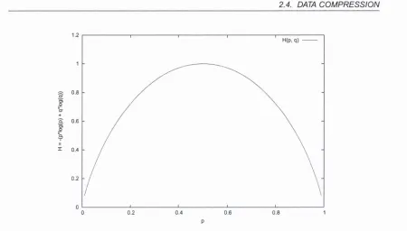
2.1 Entropy for the binary random variable with probabilities p and q = 1 - p 15
2.2 Classification o f codes ... 17
2.3 Example codes for the source symbols A , B , C , D and encoding alpha bet a j3 ... 17
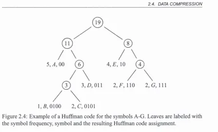
2.4 Example o f a Huffman code for the symbols A-G. Leaves are labeled with the symbol frequency, symbol and the resulting Huffman code assignment... 19
2.5 Canonical Huffman code associated with example shown in Figure 2.4 20 2.6 Construction o f a 3-bit Tunstall c o d e ... 21
2.7 Operation o f an arithmetic c o d e r ... 23
2.8 Example o f the LZ77 encoding o f a s t r i n g ... 25
2.9 Example of the LZ78 encoding of a s t r i n g ... 27
2.10 LZW dictionary after recovery of the string a a/3 a a/3 ... 28
2.11 Architecture o f Wolfe’s Compressed Code RISC P r o c e s s o r... 32
2.12 Example o f Yoshida et. al compression te c h n iq u e ... 33
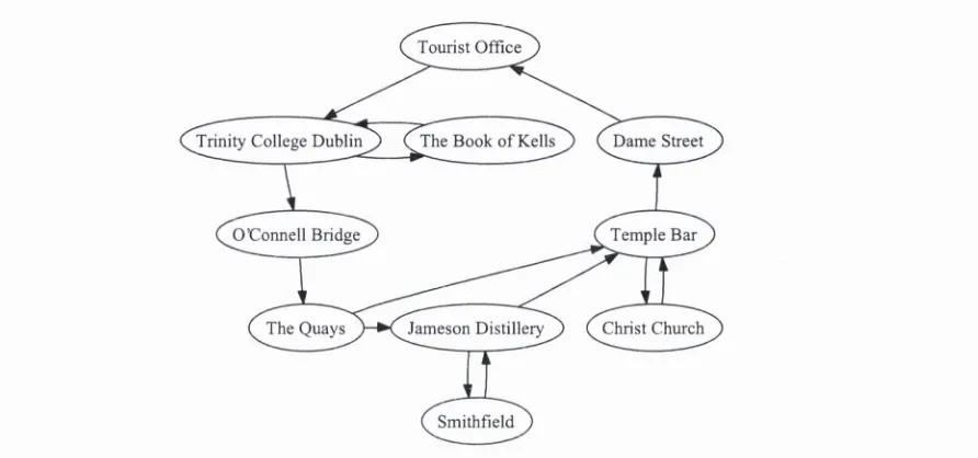
3.1 Example o f graph structured text with fixed entry point at Tourist Office 49 3.2 Immediate dominator tree associated with Figure 3.1 ... 49
3.3 A rooted directed graph and its associated immediate dominator tree . 50 3.4 Algorithm for partitioning a graph G into its in te rv a ls ... 52
3.5 Partitioning o f a graph G into in te rv a ls ... 53
3.6 Computation o f dominators within an in te r v a l... 54
3.7 Iterative algorithm for computing dominator sets ... 55
3.8 Dominator sets as computed using the iterative algorithm for the graph G* from Figure 3 . 5 ... 55
LIST OF FIGURES
3.10 Compression o f data using dictionary pre-initialized by immediate dom inator tree ... 58 3.11 Graph LZW encoded data for each node in 3.3 ( i ) ... 58 3.12 Initial structure o f dictionary during Graph LZW decompression . . . 59 3.13 Dictionary structure after traversing nodes A, C and D ... 59 3.14 Cormectivity graph extracted from our snapshot o f wap.sciam.com (The
Scientific American website, mobile e d itio n )... 60 3.15 Immediate dominator tree derived from the graph shown in Figure 3.14 60 3.16 PDA website benchmark d a ta ... 61 3.17 Compression ratios (compressed size/uncompressed size) achieved at
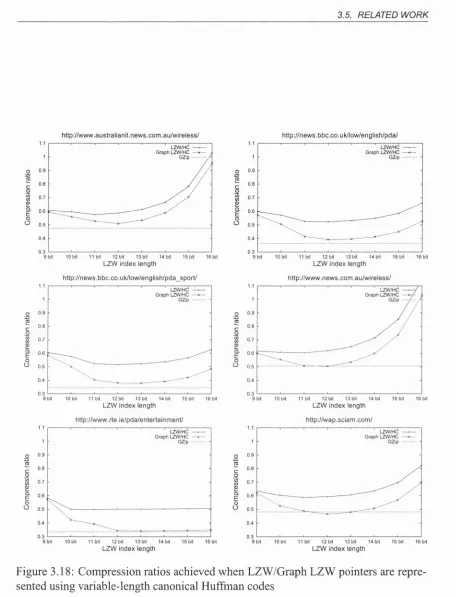
various dictionary sizes for both regular LZW and Graph LZW applied to six PDA w e b site s... 61 3.18 Compression ratios achieved when LZW/Graph LZW pointers are rep
resented using variable-length canonical Huffman codes ... 63 4.1 Example showing assembly source and its binary encoding, basic blocks
and branch blocks are also id e n tifie d ... 68 4.2 Control Flow Graph for code shown in Figure 4 . 1 ... 68 4.3 Extended Basic Blocks associated with CFG shown in Figure 4.2 . . . 68 4.4 Immediate Dominator Tree associated with Control Flow Graph in
Figure 4 . 2 ... 70 4.5 Mapping from original address space to the compressed address space 71 4.6 Encoding format for a basic block which contains no control flow in
structions (entry), and one which does G o in )... 72 4.7 High level description o f the process of fetching an instruction when
requested by the p r o c e s s o r ... 74 4.8 If the processor next issues a request for address Ox 1C, should the fall
through block be used or the compressed block located at Ox 1C? . . . 75 4.9 Appropriate program layout to avoid the problem in Figure 4.8 . . . . 75 4.10 Possible positions for decompression e n g in e ... 76 4.11 An example showing why our basic block oriented schemes must be
considered as post-cache decompression alg o rith m s... 78 4.12 Basic and Branch block size d is tr ib u tio n s ... 85 4.13 CRC immediate dominator tree (compiled with -Os and link-time op
LIST OF FIGURES
4.15 Compression ratio for 9-bit LZW applied at various variable-length
block granularities ... 88
4.16 Conditioned 16x4 Markov model for crc32 benchmark (optimized with -oO). p(0) is shown as dotted lines, p (l) as solid lines... 91
4.17 Entropy results for c j p e g ... 92
4.18 Entropy results for d j p e g ... 92
4.19 Entropy results for crc ... 92
4.20 Entropy results for i s p e l l ... 92
4.21 Entropy results for raw caudio... 93
4.22 Entropy results for raw daudio... 93
4.23 Entropy results for r ij n d a e l... 93
4.24 Entropy results for to a s t... 93
5.1 Definition o f touches-cl and touches-bb, relating basic blocks and cache lines to each-other... 98
5.2 Compulsory miss tree construction a lg o r ith m ... 99
5.3 View o f object code fi’om Figure 4.1 showing cache lines (cl), basic blocks (bb) and the touches-cl/touches-bb r e l a t i o n s ... 100
5.4 Compulsory miss t r e e ... 101
5.5 Initial dictionary; dictionary after compressing line 0; and structure o f dictionary after five lines lines from the compulsory miss tree have been c o m p r e s s e d ... 103
5.6 Encoding format for Line 0 ... 104
5.7 Block level diagram of LZW decoder p ip e lin e ... 108
5.8 Extracting a 9-bit stream from a byte s tr e a m ... 109
5.9 Compression ratio for 9-bit LZW applied at various cache line lengths 110 5.10 Compression ratio for 9-bit LZW applied at various cache line lengths over a compulsory miss tree ... I l l 5.11 c jp e g ... 112
5.12 c r c ... 113
5.13 djpeg ... 113
5.14 isp e ll... 114
5.15 ra w c a u d io ... 114
5.16 ra w d au d io ... 115
5.17 r i j n d a e l ... 115
LIST OF FIGURES
6.1 Interprocedural control flow graph (i) dominator tree (ii) and dom ina
tor DAG ( iii) ... 119
C .l c jp e g ... 140
C.2 c r c ... 140
C.3 djpeg ... 141
C.4 is p e ll... 141
C.5 ra w c a u d io ... 142
C.6 ra w d a u d io ... 142
C.7 rijndael ... 143
Chapter 1
Introduction
1.1
Overview
Reducing the size required to store a program’s object code has always been an im portant issue for embedded systems. Reduced program size decreases the memory re quirements o f an embedded device, resulting in decreased hardware production costs and lower power consumption amongst other benefits (section 2.2). In his approach to showing the incompleteness o f a formal axiomatic system, Chaitin has presented a rather disconcerting result concerning the size o f the smallest program for producing a given result [Cha99]:
L et’s call a program elegant if no smaller program written in the same programming language has the same output. ... Okay, there have got to be a lot o f elegant programs out there, infinitely many. Why? Because for any computational task, for any specific output, there must be at least one elegant program. But what if you want to exhibit an elegant pro gram? What if you want to prove that a specific program is elegant, that no smaller program has the same output? Well, it turns out that you can’t, it’s impossible!
1.1. O VERVIEW
processor manufacturers (Arm, IBM, MIPS) to develop commercial solutions to help
improve the situation (sections 2.3 and 2.6.9). More recently, the ubiquitous deploy
ment of VLIW and DSP architectures in a plethora of embedded devices has rekindled
academic interest in the topic. Code compression is one technique which emerged to
tackle the situation and has already reached a level of maturity where it is considered
appropriate for inclusion in senior undergraduate/recent graduate level textbooks and
their associated courses [Wol06, FFY04].
For applications running on bare metal (ie. without an operating system or moni
tor), compression is not generally applied to a program’s code as a whole. If it were
we would need to decompress the entire program at load-time resulting in no memory
size saving. For this reason, and given that control passes from one part of a program’s
code to another during execution, previous work has allowed decompression at run
time from arbitrary branch targets or from arbitrary instruction cache line boundaries
in the code [ABFG"''03].
When compressing object code it is imperative that the original data can be recov
ered without loss, a requirement also shared by text compression. Many object code
compression schemes have borrowed methodology from text compression algorithms
using a variety of statistical and dictionary-based models [BCW90, BWC89]. An im
portant facet used to characterize a data compression algorithm is it’s adaptivity, for
which there are three classifications: semi-adaptive, static and adaptive. A technique’s
adaptivity determines whether the model used for compression is built before com
pression begins (semi-adaptive and static), or whether its construction is deferred to
occur dynamically during compression (adaptive). With regard to adaptivity the focus
of object code compression algorithms has remained primarily on static and semi-
adaptive methods, and little attention has been paid to the class of adaptive schemes.
This emphasis of attention is a direct result of allowing decompression to commence at
arbitrary branch targets or instruction cache line boundaries, as justified in [LHJC05,
LHWOO, MS05, EEF+97, XWLOlb, LHC+03, ABFG+03, LSSC03, NMC03, OW02]
due to the presence of control flow instructions in the object code being compressed;
for example in [LHC+03] the authors note
1.2. CONTRIBUTIONS OF THESIS
With such a restriction imposed on code compression it is not surprising that many
existing compression algorithms cannot be employed directly when compressing ob
ject code as noted by Xie and Netto [XLWOl, NACA04], In [XWL03, KMH+98]
the authors explicitly identify adaptive compression models as being inappropriate for
code compression since they do not allow for random access and they depend on a
history of the preceding symbols in a sequential file. The decompression of small
blocks of object code from arbitrary positions can only be achieved by an adaptive
model that is reset before compressing/decompressing each block. However, given
the short length of these blocks, the model could not adapt sufficiently to give rise
to compression—something which justified the avoidance of LZ style algorithms in
[WC92, KW94]:
Unfortunately, the techniques used in compress are best suited to blocks of
data much larger than a cache line so it is not a practical CCRP method^
If the full context were available when compressing a program using an LZ-based
algorithm then compression might arise, but the random access requirement would be
violated [LW99b, CAP99], It is for these reasons that the LZ algorithms have been
classified elsewhere as either impractical or impossible to employ for use in object
code compression [LucOO, LW98, LW99a, LDK95, LDK99],
1.2 Contributions of thesis
The work presented in this thesis exploits the observation that, despite the claims of
other researchers, decompression from arbitrary branch targets is not required at run
time— it is sufficient to be able to start decompression from each branch target as it
is encountered during execution of the program. By a carefial analysis of the code
which is to be compressed we identify additional context, beyond the boundary of
a basic block or cache line, which can be used to condition an adaptive compres
sion model. We then demonstrate how this context can be used when compressing
object code adaptively. For one of our schemes we show that the overheads associ
ated with an implementation of the technique do not necessarily cause an excessive
slowdown in execution speed—in fact in some cases a speedup can result. As such,
we show that the pervasively claimed random access decompression requirement for
1.2. CONTRIBUTIONS OF THESIS
object code compression [LHJC05, LHWOO, MS05, EEF'*'97, XWLOlb, LHC+03,
ABFG“^03, LSSC03, NMC03, OW02] is urmecessarily restrictive; furthermore we re
fute the claims made by other researchers that adaptive compression models are inap
propriate, impractical or impossible to use for object code compression since they do
not allow for random access or fail to work well for small blocks of data [XWL03,
KMH+98, WC92, KW94, LW99b, CAP99, LucOO, LW98, LW99a, LDK95, LDK99],
While we see these results as the ultimate contributions of this thesis, our other contri
butions are as follows:
We present an adaptive technique called
Graph LZW
for compressing small quan
tities of text which are organized as a rooted directed graph. We impose a constraint on
the technique such that data encountered during a traversal of any valid path through
the graph must be recoverable without requiring the decompression of data that is not
on the path in question. The technique we present determines the set of nodes y
which
are guaranteed to be encountered before reaching node x while traversing any valid
path in the graph, and uses them as a basis for conditioning an LZW dictionary for
the compression/decompression of the data in node x. The technique trades additional
analysis undertaken at compression time for improved compression ratios over regular
LZW. Despite our superior compression results the modifications to a standard LZW
decompressor to support our Graph LZW algorithm are minor and do not contribute
any significant time overhead to the decoding routine. To the best of our knowledge
we are the first to propose compressing the content of nodes in a graph by employing
an adaptive model which has been conditioned using inter-node context.
Based on our Graph LZW algorithm we develop a new adaptive object code com
pression algorithm which is targeted at compressing variable-length program basic
blocks in RISC object code, where the decompression unit is located between the in
struction cache and the CPU. While a previous attempt was made at using LZW for
compressing variable-length blocks of straight line code for VLIW architectures (sec
tion 2.6.14), we show that their scheme is a special case of our more general algorithm
and uses only a subset of the context we identify; furthermore we demonstrate that
their technique would not be suitable for the smaller sized blocks of code typically
generated for RISC architectures (section 4.3.3).
en-1.3. THESIS OUTLINE
tries are referenced at run-time. This technique addresses a number o f shortcomings associated with our variable-length block scheme. To accomplish this we introduce a novel data structure termed the compulsory miss tree which characterizes the par tial order in which compulsory misses for a program ’s code are guaranteed to occur at run-time in an instruction cache. This technique reduces the overheads which re sulted in poor performance by the algorithm targeted at variable-length basic blocks and achieves excellent compression results. We show that the overheads associated with an implementation o f the technique do not necessarily cause an excessive slow down in execution speed. In summary it can be viewed as a new practical object code compression technique with a number o f nice properties lacked by some o f the static and semi-adaptive algorithms previously proposed.
1.3 Thesis outline
Chapter 2
Background
In this chapter we present the context in which the contributions o f our thesis should be considered. We give a short review o f the common types o f memory found in embedded systems and popular architectures for embedded code storage in section 2,1. This review allows us discuss the advantages associated with reducing the quantity of memory required for code storage in section 2.2. There are two ways in which we can reduce instruction memory requirements so that the advantages associated with reduced memory size might be realized: (i) by modifying the instruction set or (ii) by compressing the object code. In section 2.3 we discuss the design o f instruction sets from the perspective o f reducing static code size. This is followed in sections 2.4 and 2.5 by a non-exhaustive introduction to the topic o f data compression and an overview o f the compilation/execution o f an embedded application. This material is introduced in order to provide the prerequisite background material needed to discuss existing object code compression techniques in section 2.6.
2.1
Review of memory types
Computer memory is typically characterized as being either volatile random access
2.1. R E V IE W OF M EM O RY TYPES
power is supplied to the circuit, while the values stored in a DRAM will begin to decay over a period o f time and require regular refreshing to ensure that they remain error- free. A more detailed introduction to their construction and operation can be found in [MK97]. In typical desktop machines the denser capacity cheaper DRAM is the type used for the computer’s main memory while the faster SRAM is typically employed in the implementation o f caches.
The simplest type o f ROM is implemented using tiny fuses which can selectively be either blown or left intact in a memory circuit to represent the two binary states. Once a fuse is blown it carmot be repaired, so programming such ROMs is a one-off occurrence. Not all writing techniques for ROMs are as destructive. If a transistor latch which can be reset only with significant effort is employed a cross between a ROM and RAM can be built— the EPROM (erasable programmable ROM). EPROMs come in two basic types, electrically erasable (EEPROM) and UV-erasable (UV/EPROM).
Flash memory is a non-volatile rewriteable memory generally considered to be a solid state storage device. It stores information in an array o f floating gate transistor cells. There are two types; N O R based and NAND based. A NOR flash cell looks like a normal metal-oxide-semiconductor fleld-effect transistor (MOSFET) except it has two gates instead o f one— the first is the control gate (like a normal MOSFET gate) while the second is a floating gate. NOR based flash has a long erase and write time, but has an interface that allows random access to any location making it suitable for storage o f program code. NAND flash on the other hand has faster erase and write times, higher density and lower cost per bit than NOR flash. Its I/O interface only allows sequential access to data making it useful for mass storage devices, but less appropriate as a regular computer memory.
2.2. ADVANTAGES OF MEM O RY SIZE REDUCTION
2.2 Advantages of memory size reduction
In this section we describe four advantages associated with code size reductions which allow for reduced memory requirements. We will discuss improvements in battery life due to decreased energy consumption, increases in performance due to reduced mem ory access time, reductions in production costs due to increased yield and reductions in software development/maintenance costs due to effective memory size increases.
2.2.1
Improvements in battery life
Power is typically defined as a measure o f the rate at which work is done by a system and energy as the total work done over a period o f time. In the context o f computing systems work generally refers to activities associated with the execution o f a program’s instructions, while power and energy consumption are the rate and total amount o f electrical energy consumed by the system [VF05], There are two contributors to the total power consumption o f an electronic circuit: dynamic pow er and static power. The dynamic power consumed is that caused due to switching activity within the circuit (when a value changes from 0 ^ 1 or vice-versa). Static power on the other hand is drawn by the circuit irrespective o f whether the circuit is switching or idle and is caused by imperfections in the construction o f transistors. While dynamic power is the main source o f power dissipation in CMOS devices, the contribution o f static power is becoming increasingly significant as circuit implementation technology scales down in size.
Since DRAM requires frequent refreshing o f the charge stored in its capacitors it consumes more power than an SRAM equivalent. By reducing the size o f a DRAM— for example, by using a code size reduction technique in a system which executes instructions directly from DRAM— the dynamic power dissipation o f the circuit can be reduced due to the reduction in the switching activity o f the module during these refresh cycles.
Leakage power, one component o f static power consumption in a chip, is propor
tional to the leakage dissipated in all o f a circuits transistors regardless o f the memory type being employed [VF05]. By reducing the capacity o f a transistor based memory due to decreased code size we can help remove the impact o f static power dissipation.
2.2, ADVANTAGES OF M EM O RY SIZE REDUCTIO N
program, the energy consumption o f an embedded device can be reduced thus increas ing battery Ufe.
2.2.2 Increases in performance
Smaller memories can generally be read faster than their larger equivalents, for exam ple in 2001 a flash memory o f 16Mb capacity had an access time o f 65ns compared with an access time o f 150ns for a memory o f 128Mb [PH90]. A combined code/data memory that has been decreased in size may result in performance increases for the system due to reduced memory access time.
While such a performance increase can be achieved as a result o f any technique which results in reduced memory requirements, previous work investigating object code compression has shown that performance can further increase in the presence o f a code compression technique when the backing memory is relatively slow. This happens due to the reduction in time spent accessing memory since less data must be fetched, and was observed in [WC92] when high instruction cache miss rates were encountered during program execution.
2.2.3 Decreases in manufacturing costs
In many control oriented embedded systems program memory size overshadows the size and cost o f the processor. In a high end hard disk drive an embedded processor might occupy an area o f 6mm^ while the program memory for the processor requires 2 0 -4 0 m m 2 [KMH+98].
When manufacturing an integrated circuit, a circular silicon wafer is tested and chopped into dies that are packaged. The cost o f the final circuit can be estimated once the number o f dies that will fit on a wafer and the percentage o f those that are not defective (referred to as die yield) have been determined.
^ ^ C o sto fw afer ^
Cost o f die = ^ ^ (2. 1)
Dies per wafer * Die yield
2.2. ADVANTAGES O F MEM O RY SIZE REDUCTION
2 Wafer diameter \
Dies per wafer =
2
)
K * Wafer diameter (2.2)Die area -\/2 * D ie area
where the first term is the ratio o f wafer area to die area and the second compensates for the problem o f rectangular dies near the edges o f round wafers. The following formula is an empirical model developed after investigating the yield o f many manufacturing lines:
Defects per unit area is a measure o f the defects that occur at random during man ufacturing. In 2006 it was typically 0.4 defects per square cm in a 90nm process. The parameter a corresponds to the number o f critical masking levels— a measure o f manufacturing complexity. In a multilevel metal CMOS process in 2006 a reasonable estimate was a = 4.0
The manufacturing process dictates the wafer cost, wafer yield and defects per unit area, leaving the die area as the sole parameter under control o f a computer architect. In practice the number o f good dies per wafer, and hence the cost per die, grows roughly as the square o f the die area [PH90]. Employing a code compression technique to reduce the size o f physical memory required to store program code in a system on a chip embedded design offers the possibility to reduce overall die size, increasing die yield and thus decreasing manufacturing costs.
2.2.4 Reductions in software development costs
Rather than considering the reduction in code size as a technique to shrink the chip size, it can be considered as an effective enlargement o f its memory capacity. In creasingly the development o f embedded software is being undertaken in high level languages which are compiled into machine code. While this results in cheaper and faster software development and maintenance, compilers still typically produce code that is more verbose than its hand-coded counterpart and requires care by the program mer in preparation o f the input [Bun08], [Gan04, Chapter 18— Understanding Your C Compiler: H ow to Minimize Code Size], This shift can be attributed in part to the fact that total software cost in the design o f an embedded system-on-a-chip is greater than
Defects per unit area * Die area — a Die yield = Wafer yield * 1 I
2.3. INSTRUCTION SET ARCHITECTURE DESIGN
the total hardware design cost for design processes under 130nm [IBS02], Having a larger effective memory can justify the use o f high level languages and cut the cost o f programmer productivity without exacerbating the problem o f overall chip size and manufacturing cost.
2.3 Instruction set architecture design
Having reviewed the main advantages associated with reducing instruction memory size, we now turn our attention to a review o f techniques which allow for such size reductions. In this section we discuss the design o f instruction sets from the perspec tive o f keeping static code size small and continue the review in section 2.6 with a discussion o f code compaction and compression after prerequisite information on data compression and compilation are presented in sections 2.4 and 2.5.
In the early 90’s the verbosity o f RISC code when compared to its CISC counterpart was considered a problem for the manufactures o f embedded systems. This resulted in a trend from the manufacturers o f embedded processors towards developing a reduced- width encoding o f the most frequently used instructions in their fixed-width 32-bit architectures [Sch98]. This was undertaken in the hope that RISC code would become competitive with CISC code in terms of the demands placed on instruction memory storage requirements. With increasingly diverse processor microarchitectures finding their way into embedded devices, such as Very Long Instruction Word (VLIW) and Digital Signal Processor (DSP) based cores, the design o f instruction sets from the perspective o f keeping static code size small has become common practice. In this section we review the problems and associated solutions related to reducing static code size which have been adopted by instruction set architecture (ISA) designers for RISC, CISC and VLIW/DSP architectures.
2.3. INSTRUCTION SET ARCHITECTURE DESIGN
function level based on profiled executions [KG03]. Where performance is critical the base ISA is employed, while code that is executed relatively infrequently is encoded using the Thumb/MIPS16 ISA thus balancing performance against reduced code size. Using code compression techniques (which will be described later in this chapter) does not increase the number o f actual machine instructions executed, unlike MIPS16e and Thumb/Thumb2, nor does it restrict the number o f registers, operations and modes made available from the underlying processor.
CISC code is generally considered more dense than RISC code as the ISA con tains instructions capable o f performing more complex operations and is encoded us ing variable-length instruction codewords. For example, Intel’s x86 architecture in structions can be encoded using anywhere between one and fifteen bytes and contains individual instructions capable o f operations such as comparing entire strings in mem ory for equivalence. While the ISA can be used to write fairly dense code this comes at the expense o f additional hardware overhead for both decoding and executing instruc tions. Recent microarchitectural approaches to implementing CISC instruction sets de code individual CISC instructions into RISC instructions and execute them on a RISC processor subsystem [BYTJ05, SS95, SGCOl]; hence, depending on the microarchi tecture, CISC processors might be considered to be compressed code processors.
Verti-2.4. DATA C O M P R E SSIO N
cal NOPs can be removed by the introduction o f a multi-cycle NOP instruction while the removal o f Horizontal NOPs require a little more effort, as their removal impacts the processor decode logic. In the TMS320C6x range o f DSP processors the removal of horizontal NOPs is accomplished by drawing a distinction between fetch-packets and execute-packets so that NOP instructions are not stored in the program code explicitly and are inserted during instruction issue as required [InsOO], This is accomplished by explicitly indicating in the instruction stream which instructions should be issued in parallel with subsequent instructions, and a single bit is reserved in all instructions as an indicator o f where execute packets terminate. Each instruction encodes which func tion unit it should be executed on, and NOPs are issued to any unit which will not be issued an instruction from the instruction stream during a given cycle. Nevertheless in order to take advantages o f instruction level parallelism, compilers for VLIW architec tures typically apply a number o f code transformations which increase the size o f the object code (such as procedure inlining and loop unrolling), a problem not addressed by clever ISA design.
2.4 Data compression
Data compression (also known as source coding) is the process o f encoding a body o f data D into a smaller body o f data A(D) to be decoded back to D or some acceptable approximation to £) at a later time. In general it is applied to data to remove all o f its natural redundancy, and the encoded data is subsequently coded using an appropriate
channel code designed to match the characteristics o f a noisy communication medium
thus ensuring the data can be recovered without error. Not all data can be compressed [Sto88], Both source and channel coding are the fundamental concerns o f the field o f Information Theory, whose foundations were laid in Claude Shannon’s seminal pa
per A Mathematical Theory o f Communication [Sha48]. In this thesis we concern
ourselves only with the process o f source coding and we review the most important foundations o f this topic as they apply to the field o f data compression in the following section. After this background material is introduced we describe the classification o f practical compression algorithms in section 2.4.2 and then review a number o f popular
2.4. DATA C O M P RE SSIO N
1.2
H(P. q)
---cr 0.8
\
\
0
0 0.2 0.4 0.6 0.8
[image:32.515.38.488.52.308.2]P
Figure 2.1; Entropy for the binary random variable with probabilities p and q = 1 - p
2.4.1
Entropy, instantaneous codes and the Kraft inequality
In his model o f a communication system Shannon describes a discrete information
source as generating a message symbol by symbol choosing successive symbols ac
cording to certain probabilities. Given an information source characterized by an al
phabet 'Lsource o f « symbols occurring with associated probabilities p\,pi^---pn lets
assume we can measure how much uncertainty there is associated with the selection
o f a particular symbol and denote it H{p\.,p2,...pn)- Shannon defines three properties
that would seem appropriate for such a measure {H is continuous in the pi, if all pi are
equal then H should be a monotonic increasing function o f n, and finally if a choice is
broken down into two successive choices the original H should be the weighted sum
o f the individual values o f H), and demonstrates that the only function H satisfying the
requirements is
This value H or the entropy o f a set o f probabilities has a number o f properties that
substantiate it as a reasonable measure o f information; for example H = Q only if all
the Pi but one are zero, thus when we are certain o f the outcome H vanishes. For a
given «, / / is a maximum and equal to log{n) when all the />, are equal, which is also
the most intuitively uncertain situation. Taking K as 1 and logarithms to the base 2
gives us the measure in bits. An example is shown in Figure 2.1.
n
2.4. DATA COMPRESSION
We now turn our attention to the practical constraints associated with assigning
codewords to symbols generated by an information source. A code C ; '^source '^code*
is non-singular if each symbol from 'Lsource is mapped to a different non-empty string over the code alphabet 'Lcode- x ^ x' => C{x) ^ C{x'). It is uniquely decodable if, given a string over the source alphabet, the concatenation o f the encoded symbols is
non-singular; in other words, given an encoded message there is at most one source
message which will generate that message. Note that the entire string may need to be
processed before even the first symbol in the source string can be determined. A code
is called a prefix code or instantaneous if no codeword is a prefix o f another code
word. An instantaneous code can be decoded without reference to future codewords.
The relationship between the sets o f code types and an example o f each type is given
in Figures 2.2 and 2.3 respectively. In this thesis we will be interested in uniquely
decodable codes, in particular those which are prefix free.
The Kraft inequality [Kra49] states that for any instantaneous code o f k codewords over an alphabet o f size D the codeword lengths l \ , h , - - - J k must satisfy the following
inequality:
T - L <
i
ffl'.
-The proof is rather straightforward and is based on constructing a D-ary tree and considering the constraints on the number o f leaf nodes at depth max{lk) by classifying the nodes at that depth as either codes, descendants o f codes, or neither. What is less
obvious is that this same inequality also gives necessary and sufficient constraints on
the codeword lengths required for any uniquely decodable code, as proven by McM il
lan [McM56]. The result is generally referred to as the Kraft-McMillan inequality.
An elegant proof that Shannon’s entropy H gives a lower bound on the average message length attainable for uniquely decodable messages follows fi'om this inequal
ity and is given in [Rez61] based on the observations in [McM56].
2.4.2 Classification of compression algorithms
Data compression techniques may be classified according to a number o f facets which
include their fidelity, model type and adaptivity. The fidelity o f a scheme is either
lossless or lossy. Lossless algorithms allow the original data be reconstructed perfectly
after being compressed and subsequently decompressed. This contrasts with lossy
2.4. DATA C O M P R E SSIO N
[image:34.515.44.479.43.380.2]All codes N o n sin g u lar codes U niquely decodablc codes Instantaneous codes
Figure 2.2; Classification o f codes
1. N ot non-singular { A i-> a, B ^ a . C1—> ccfi, Z ) ^ / 3 }
2. Non-singular, but not uniquely decodable {A !-»• a , C 1—^ a/3, D H-» /3 a }
3. Uniquely decodable, but not instantaneous { A ^ P a , B ^ a a , C ^ / 3 j 3 , Z )H ^/3/3a}
4. Instantaneous { A H-» a, B /3 a , C1—* /3/3cx, D /3/3/3a}
Figure 2.3: Example codes for the source symbols A , B ,C ,D and encoding alphabet a/3
the input as part o f the compression process in return for improved size reduction.
Models are described as either statistical or dictionary-based. In a statistical model
the probability o f each input symbol occurring is determined. This allows an alloca
tion o f variable-length binary codes to each symbol in the input, such that symbols
with a high probability o f occurrence are given short codes while less likely symbols
are given longer ones, subject to the constraints imposed by the Kraft-McMillan in
equality. Dictionary-based models operate by moving commonly occurring sequences
of symbols from the input to a dictionary (table). Each occurrence o f one o f these
sequences may then be replaced by a shorter codeword indexing the appropriate dic
tionary entry.
There are three adaptivity classifications: semi-adaptive, static and adaptive. In a
semi-adaptive scheme the data to be compressed are first analyzed in their entirety, an
appropriate model is then built, and finally the data is encoded. The model is stored as
part o f the encoded data, as it is required by the decompressor to reverse the encoding.
Static schemes are similar to this, but a representative selection o f data is used to build
a fixed model which is hard-coded into compressors and decompressors. This has the
2.4. DATA COM PRESSION
disadvantage that poor compression will result if the model is not representative o f data presented for compression. Finally, adaptive techniques commence coding with an empty (or statically determined) initial model, and update this model as the coding o f each successive input symbol occurs. W hen decoding compressed data, the same initial model used for compression is constructed and is appropriately updated as each symbol is recovered. This not only removes the need for the model to be explicitly transmitted or stored with the encoded data, but also facilitates tailoring the model to the particular data being compressed.
In the following sections we review a number o f well known lossless general- purpose data compression techniques in preparation for discussing existing work on the compression o f program object code later in this chapter.
2.4.3 Huffman coding
Huffman codes [Huf52] are optimal codes when the output o f an information source is coded one symbol at a time. To construct a Huffman code the data to be compressed are analyzed and a count o f the frequency o f occurrence o f each symbol in the input alphabet X (for example, each byte or word) is determined. Using this information, variable-length binary codes are assigned to input symbols so that those appearing fre quently are given short codes while those appearing infrequently are allocated longer ones [BCW90], These variable-length codes are constructed so that the prefix-property holds, that is, no code is a prefix o f any other code. When compressing data the original symbols are replaced by their corresponding Huffman codes and stored in the output. The output also includes a table containing the mapping from Huffman codes to the input alphabet symbols for use by the decoding algorithm. Hence Huffman coding is an example o f a lossless, statistical, semi-adaptive technique. Decoding occurs by sequentially matching Huffman codes to the encoded data and outputting the corre sponding symbols.
To construct a Huffman code we begin with a set o f nodes q, each o f which rep resents a single source symbol and its associated fi'equency o f occurrence. This set is
2.4. DATA COMPRESSION
@ 3, A O il 2 ,F , 110 2, G, 111
[image:36.514.40.488.47.318.2]1 ,5 ,0 1 0 0 2, C, 0101
Figure 2.4: Example o f a Huffman code for the symbols A-G. Leaves are labeled with the symbol frequency, symbol and the resulting Huffman code assignment.
the least frequently occurring ones are stored at the greatest depth in the tree. The
Huffman code is then assigned by considering each left branch from an internal tree
node to generate a 0 while the right branch generates a 1. The code for a symbol X is determined by reading the sequence o f Os and 1 s required to form a path from the root
o f the tree to the node representing the symbol. A simple example o f Huffman coding
is presented in Figure 2.4.
2.4.4 Canonical Huffman codes
While textbooks either omit a discussion o f the decoding procedure (a correct decoding
procedure is obvious), or describe it as a bit-by-bit process where you look at a bit and
either go left or right in a reconstruction o f the tree which was built for the code, this
is slow. Given the lengths o f codes for a Huffman code, we can build a tree with
leaves at the same depths but with a different overall structure. This structure leads to
some nice mathematical properties which can be exploited to reduce the overhead of
storing and transmitting the encoding tree (or rebuilding it), and improve the decoding
implementation. This restructuring gives rise to Canonical Huffman codes which were
introduced by Schwartz and Kallick [SK64] and Connell [Con73].
The canonical Huffman code associated with the Huffman example we introduced
earlier is shown in Figure 2.5. Note that we build the tree by filling the tree from the
left to the right with the smaller to bigger codewords. The binary assignment o f codes
2.4. DATA COM PRESSIO N
O
O O
A, 00 E, 01 O O
D, 100 F, 101 G, 110 O
B , 1110 C, 1111
Figure 2.5: Canonical Huffman code associated with example shown in Figure 2.4
canonical Huffman codes is a misnomer). Codes o f the same length increase by a value
o f 1, and the first code o f length /, can be determined from the last code o f length /,■_ |
by adding one and multiplying by two. It is this property that leads to an efficient
transmission o f the coding table/coding tree, and the efficient decoding procedure.
More recently canonical Huffman codes were reconsidered by Hirschberg and Lelewer
and the interested reader should read [HL90, Method B] for implementation details.
2.4.5 Tunstall coding
While Huffman codes map fixed symbols to variable-length codes, Tunstall codes
[Tun67, Say96] instead take a variable-length sequence o f source symbols and encode
the group using a fixed-length code; hence it is a variable-to-fixed code. The design
o f a variable-to-fixed code should satisfy the following two conditions: (i) we should
be able to parse any source output sequence into a sequence o f symbols that appear
in the codebook and (ii) we should maximize the average number o f source symbols
represented by each codeword.
Given a set o f symbols {^i ..i'w} and associated probabilities x/ = p{si) a static «-bit
Tunstall code (in which there are 2" codewords) can be built as follows. We initialize
a codebook to contain each o f the N source symbols. Next we remove the entry with
the highest probability max{xi) and insert into the codebook a sequence o f new entries
constructed by appending to this entry each source symbol. Each o f the new entries
will now have an associated probability which is the product o f the probabilities o f the
2.4. DATA C O M P RE SSIO N
Sequence Probability Code
7 0.1 000
Pa
0.2 001PP
0.25 010P
y 0.05 Oilaa
0.16 100ap
0.2 101ay
0.04 110Sequence Probability
a 0.4
7 0.1
Pa 0.2
0.25
p y 0.05
Sequence Probability
a
0.4P
0.57 0.1
(i) (ii) (iii)
Figure 2.6: Construction o f a 3-bit Tunstall code
o f codewords in the codebook is < 2". When we have finished inserting new entries
into the codebook, we can arbitrarily assign each entry a binary code o f «-bits.
For example, consider building a 3-bit Tunstall code for the source alphabet a , /3, y
with probabilities 0.4, 0.5 and 0.1 respectively as is demonstrated in Figure 2.6. Con
struction o f the codebook terminates after two iterations, as a third iteration would
generate more entries than the code can accommodate. An arbitrary assignment o f
3-bit codes is made and shown in Figure 2.6 (iii).
2.4.6 Arithmetic coding
Unlike Huffman coding which separates the input message to be coded into its individ
ual symbols and replaces each symbol with a codeword, arithmetic coding [WNC87]
encodes the entire message into a single number n such that 0 < n < 1.0. Huffman coding is optimal in the sense that the codewords it assigns are the shortest codes pos
sible when the encoding is performed symbol by symbol. Since it assigns integral
length codewords to each symbol the redundancy o f the Huffman code can be sub
stantial when compared to the entropy o f a source in the presence o f highly skewed
probabilities; consider an alphabet with one symbol whose probability o f occurrence
is very close to 1. Such a symbol transmits little information but the Huffman code
will need to transmit one bit per occurrence o f this symbol.
The advantage o f arithmetic coding is that the entire message is encoded in a sin
gle codeword, and integral length codes for each constituent symbol in the message
need not be employed. The code generated for a given message is optimal in theory,
and very nearly optimal in practice (it requires H + 2 / m bits, where m is the number o f source symbols). Furthermore, when multiple probability distributions are used to
describe the source (such as pairs o f data which are generated with separate probabili
2.4. DATA C O M P R E SSIO N
o f these statistical differences. Arithmetic coding on the other hand is ideally suited
to such situations as there is a very distinct and clean interface between a probability
model and the arithmetic coder which generates the code for an input. An example o f
an arithmetic code which corresponds directly to a Huf&nan code is employed in Lang-
don’s tutorial on arithmetic coding [GGL84], and can be a useful aid in understanding
the algorithm.
The implementation o f an arithmetic coder is a rather involved process, and is one
factor contributing to the ongoing popularity o f Huffman’s algorithm which is rela
tively simple to implement. In the remainder o f this section we give an overview o f
the operation o f an arithmetic coder, assuming the code is implemented using infinite
precision fixed point arithmetic. Proofs o f the uniqueness and optimality o f the tech
nique are given in [Say96, Section 4.4.1]. A practical implementation written in the
C programming language, which uses fixed precision integer arithmetic is provided in
[BCW90], W hile it provides an implementation that is safe, the arithmetic operations
for encoding and decoding can be slow and Howard and Vitter address these issues
by pre-computing tables which allow the replacement o f arithmetic operations with
simple table lookups, giving rise to an approximate arithmetic coder with only mini
mal loss o f compression efficiency [HV91, HV94], Such implementation details are
beyond the scope o f our review here and the interested reader should read about the
techniques in the appropriate literature.
Given an alphabet o f symbols S = { a , p , y , 5 } with corresponding probabilities
p { a ) = 0.3,/7(j3) = 0.3,p{y) = 0.2,p{5) = 0.2 a message aj3j35 is encoded using an
arithmetic code as follows. The half-open interval [low, high) is initialized to [0.0,1.0),
and then partitioned into « = |2| subintervals such that the size o f each subinterval
corresponding to a symbol is proportional to the probability o f occurrence o f that sym
bol. This is easily accomplished using the cumulative probabilities o f the symbols to
determine these subinterval bounds. The subinterval which corresponds to the first
symbol to be encoded is selected, and the bounds o f that subinterval becomes the new
[low,high). The process is repeated for each symbol in the input until the entire mes
sage has been encoded, and a binary code is generated by taking the midpoint of the
final [low,high) interval and truncating it to + 1 bits. The encoding
process is shown in Figure 2.7.
The code c generated to represent aj3j35 is the rational number 0.1413. To decode
this back into the original message we intiailize the range [low, high) to be the first
2.4. DATA C O M P RE SSIO N
0.3 0.6 0.8
0.0
0.0
0.09
0.117
0.1386
0.144
[image:40.515.46.487.52.406.2]0.144
Figure 2.1 \ Operation o f an arithmetic coder
into the same subintervals used when encoding the first symbol o f the message. We locate the interval in which the number c falls [0,0.3), and see that it corresponds to
the symbol a . This symbol is output, and now the interval in which it was contained
is partitioned appropriately based on the symbol probabilities. To recover the second
symbol we note that the codeword c falls into the second interval [0.09,0.18) corre sponding to j3 and output that symbol, and continue in this fashion until the entire
message has been recovered.
2.4.7 LZ family of algorithms
The algorithms developed by Ziv and Lempel are adaptive dictionary based data com
pression techniques. The basic idea exploited by the algorithms is to replace a repeated
string by a reference to a previous occurrence o f itself, rather than directly attempt to
derive codes for each symbol in the source based on Shannon’s entropy (referred to
as entropy coding). They form the basis for a rather large family o f data compres
2.4. DATA COM PRESSIO N
[ZL77] or the LZ78 [ZL78] algorithms. The original papers describing the LZ algo
rithms are rather theoretical and disguise simple and elegant compression techniques in
the form o f mathematical papers. A more accessible description o f the two algorithms,
on which the following two sections are based, is presented by [BCW90].
LZ77
The LZ77 technique uses a sliding window o f N characters over a string which is to be
encoded. Within the window the first N — F characters have already been processed,
and the remaining F characters represent the next part o f the data to be encoded and
will be referred to as the lookahead. A match o f maximal length from the data in the
lookahead to any position within the entire buffer which starts in the first N positions
is found at position /. A pointer consisting o f the triple {i,j,k) is output where i is
the index o f the start o f the match in the buffer, j is the length o f the match and k is
the next character in the lookahead which was not matched into the buffer. The buffer
moves forward j + 1 positions and the process is repeated until the entire string has
been encoded. The original string can be recovered by interpreting each (i, j , k) triple
in sequence and re-expanding the data. Each pointer is encoded using |’/og(A^—F )] +
\log{F)] + [/og(|Z|)] bits. Ziv and Lempel showed that this technique performs at
least as well as any semi-adaptive dictionary designed specifically for compressing the
string being encoded, if N is sufficiently large.
We show the process o f encoding a string over the alphabet Z = { a , j3, 7} in Figure
2.8. The sliding window is indicated using the [] brackets and the distinction between
the data already encoded and the lookahead is indicated using a |. A — is used to rep
resent a null character, which initially fills the section o f the sliding window dedicated
to data already processed.
By varying the choice o f window size and the technique employed for encoding
the components o f the LZ77 pointers (using either variable-length encodings o f the
integers, or Huffman encoding the pointer components), and indeed allowing a mix
o f arbitrary characters and pointers, a number o f variations on the LZ77 technique
have been derived, such as LZR, LZSS, LZB and LZH [BCW90]. In principle these
algorithms are the same as LZ77; the differences are in their implementation details.
LZ78
A piece o f LZ78-coded data is comprised o f a sequence o f {i,j) pairs, where i is a
2.4. DATA COM PRESSION
a^a^y^ya
[—
aj3a]/37j3ya
(0,0,a)
-[-a\j5aP]YPyoc
(0,0,j3)
—
[aP\aPy](5ya
(0,2,7)
—
aj5a[Py\Pya\
(0,2,a)
Figure 2.8: Example of the LZ77 encoding of a string
from the input alphabet. Initially the dictionary is empty and location 0 is initialized
to be the empty string e. The dictionary is then searched for the longest phrase which
is a prefix of the input data. The index / for this phrase is output in the compressed
encoding along with the next character
j
from the input which was not matched to the
dictionary and a new entry, consisting of the phrase just matched concatenated with
j,
is inserted into the dictionary. Coding continues in this fashion, restarting at the next
unprocessed symbol in the input. When the entire dictionary is fiill no more entries
can be added and the remaining input data is coded using the dynamically-constructed
dictionary.
Decompression of LZ78 coded data starts with the same initial dictionary that was
used for compression. The dictionary index is extracted from the codeword pair
{ij)
and is used as an index to the dictionary and its corresponding phrase is output to the
decompressed stream, with the symbol
j
appended. This new phrase just output is
also inserted into the dictionary at the next available location to ensure the dictionary
is kept in synchronization with that generated during compression. The dynamically
constructed dictionary encodes a history of previously encountered phrases in the input
stream and gives rise to compression when a code (dictionary index) is output in place
of multiple symbols from the input stream during coding.
We show an example of encoding a string over the alphabet S = {a,/3,y, 5} in
Figure 2.9. At each step we indicate the position from which coding will occur using
a
I ,show the dictionary before it is updated at this step, and the resulting sequence of
LZ78 pointers which encode the string after this step is finished.
LZ78 will code an indefinitely long string in the minimum size dictated by the
entropy of the source. Note however that most sequences of data are substantially
shorter than an infinity. A big benefit of the LZ78 technique is that some variants lead
2.4. DATA COMPRESSION
are generated for insertion into the dictionary and for adaptively removing those which
are not being used frequently gives rise to a number of variations on the algorithm
such as LZC, LZT, LZMW, LZJ, LZFG and LZW. In the next section we describe the
LZW variant, which we used as a representative adaptive dictionary based algorithm
in developing our techniques later in this thesis.
LZW
LZW [Wel84] is a popular variant of LZ78 which eliminates the inclusion of an ex
plicit character in the output after each phrase, which is often wasteful. It is classified
as lossless, dictionary-based and adaptive. It eliminates the need to output an explicit
character after each phrase by initializing the dictionary to contain the set of all sym
bols from the source alphabet Z. During encoding the character component of each
LZ78 phrase is encoded as the first character of the next LZW phrase. This is possible
since the dictionary already contains all characters from the source alphabet, and so
a mechanism for introducing characters to the dictionary which have not previously
been encountered is unnecessary.
Decompression of LZW coded data starts with the same initial dictionary that was
used for compression. Each codeword to be decompressed is used as an index to the
dictionary and its corresponding phrase is output to the decompressed stream. Then
the first symbol from the phrase in the dictionary indexed by the next codeword in the
compressed stream is appended to the phrase just decompressed, and this sequence is
then inserted as a new entry in the d