Applying visualisation to model-based formal
specifications.
PARRY, Paul William.
Available from Sheffield Hallam University Research Archive (SHURA) at:
http://shura.shu.ac.uk/20208/
This document is the author deposited version. You are advised to consult the publisher's version if you wish to cite from it.
Published version
PARRY, Paul William. (2004). Applying visualisation to model-based formal specifications. Doctoral, Sheffield Hallam University (United Kingdom)..
Copyright and re-use policy
See http://shura.shu.ac.uk/information.html
Fines are charged at 50p per hour
-
h
OCT 2005
off,'\
2 2 AUG 2007
^
ProQuest Number: 10700853
All rights reserved
INFORMATION TO ALL USERS
The quality of this reproduction is dependent upon the quality of the copy submitted.
In the unlikely event that the author did not send a com plete manuscript and there are missing pages, these will be noted. Also, if material had to be removed,
a note will indicate the deletion.
uest
ProQuest 10700853
Published by ProQuest LLC(2017). Copyright of the Dissertation is held by the Author.
All rights reserved.
This work is protected against unauthorized copying under Title 17, United States C ode Microform Edition © ProQuest LLC.
ProQuest LLC.
789 East Eisenhower Parkway P.O. Box 1346
Applying Visualisation to
Model-Based Formal
Specifications
Paul William Parry, B.Sc. (Hons)
A thesis submitted in fulfilment of the requirements of
Sheffield Hallam University for the Degree of Doctor of
Philosophy
Abstract
The most important and challenging activity in developing new software systems is arguably ascertaining their features and characteristics before development takes place. This activity, known as requirements engineering, involves software developers identifying the requirements of the customers who are procuring the system, and then documenting them in a requirements specification.
Producing a requirements specification is a complex, time consuming and human- centred activity. It is essential that both parties discuss the requirements, analyse them and negotiate any issues, uncertainties or conflicts that arise. To assist in this process, a prototype of the software can be developed and then thrown away after the requirements process has been completed. Such a prototype helps to stimulate discussion and to provide a vehicle for experimentation and evaluation. This form of prototyping is now a popular and well-known requirements engineering technique.
One powerful throwaway prototyping approach involves developing prototypes quickly using executable model-based formal specifications. These are based upon mathematical notations that possess a defined syntax and semantics. They have a useful dual role in the requirements process. On the one hand, they can be used to express requirements specifications in a precise and unambiguous manner, whilst on the other they can also be subjected to execution to produce a prototype.
However, despite the benefits that such executable specifications have for the developer, their use can be problematic in situations that involve communication with customers. This is because traditionally, for reasons of productivity, the execution behaviour of prototypes developed in this manner is often depicted using developer-centred representations. Such representations often do not correspond to the perceptions or expertise of the customer, as they are often too abstract or technical. If the customer cannot recognise or comprehend these, accurate evaluation of the prototype cannot take place, stifling much needed dialogue and rendering the prototyping process ineffective.
This research advocates that applying visualisation to this form of prototyping can alleviate the problems of comprehension and the subsequent breakdown in dialogue. The objective is to employ the techniques and principles of visualisation to transform the developer-centred prototype execution behaviour into customer-oriented representations based upon pictorial and graphical forms from their own universe of discourse. Applying visualisation in this way can retain the advantages of using executable formal specifications to build prototypes, while at the same time stimulating and sustaining effective dialogue between developers and customers.
The objective of the research concerns the production of a system for visualising the execution of a specific executable formal specification-based prototype development technique. The resulting system is then evaluated by demonstrating its application in a series of case studies. These reveal the capabilities of the approach, and demonstrate the benefits that can be gained over and above the use of existing prototyping techniques based on executable formal specifications.
Acknowledgements
A work of such magnitude as this is not undertaken and completed without the help, encouragement and motivation from colleagues, friends and family.
I would first like to express my gratitude to Sheffield Hallam University for providing the opportunity and resources to complete the work. I would also like to extend many thanks to my friends and colleagues within the School of Computing and Management Sciences at Sheffield Hallam University who have offered advice and encouragement throughout the duration of the research.
I would also like to acknowledge the work of Dr. Richard Hibberd, who developed the ZAL system, and Dr. Graham Buckberry who developed TranZit. The work in this thesis integrates closely with these systems.
In addition, I would like to thank my good friend Jo Sutherland for proof reading the thesis after its completion. This, I realise, was no small task.
A great deal of thanks must be expressed to my supervisory team, Dr. Mehmet Ozcan and Mr. Ian Morrey, for their enthusiasm, guidance, and technical expertise. However, this thesis would not have been written without the generous support and encouragement of Professor Jawed Siddiqi. Indeed, I have been extremely fortunate in having Jawed as my Director of Studies. His direction, constructive criticism and help whenever I have needed it have been very much appreciated. I have the utmost respect for him and will always be in his debt. Thankyou is simply too small a word.
Last, and by no means least, I would like to express gratitude to my family. My sister Nicola and Brother-in-law Shaun and their family, and my grandmother Emma, all deserve recognition as they have all offered support during the research. The most gratitude must go to my mother, Margaret. She has supported and encouraged me during all my studies, from school, throughout university and throughout my doctoral research. Her strength, determination and love continue to be a source of inspiration in my life. Finally, these acknowledgements would not be complete without mentioning my late grandfather Bill Rollinson. I just wish he were here now to see how far I have come.
Table of Contents
Chapter 1 - Introduction
1.1 Problem Definition and Research Proposal...10
1.2 Research Contribution ... 12
1.3 Thesis Structure...13
Chapter 2 - Background and Motivation 2.1 Requirements Engineering... 16
2.1.1 The Product of Requirements Engineering...18
2.1.2 The Requirements Engineering Process...20
2.1.3 Requirements Prototyping... 23
2.2 Presenting Prototype Execution Behaviour...26
2.2.1 Critical Factors in Presenting Prototype Execution Behaviour... 27
2.2.2 Applying Visualisation to Present Prototype Execution Behaviour...30
2.2.3 Challenges in Visualising Prototype Execution Behaviour... 35
2.3 Survey of Existing Approaches...41
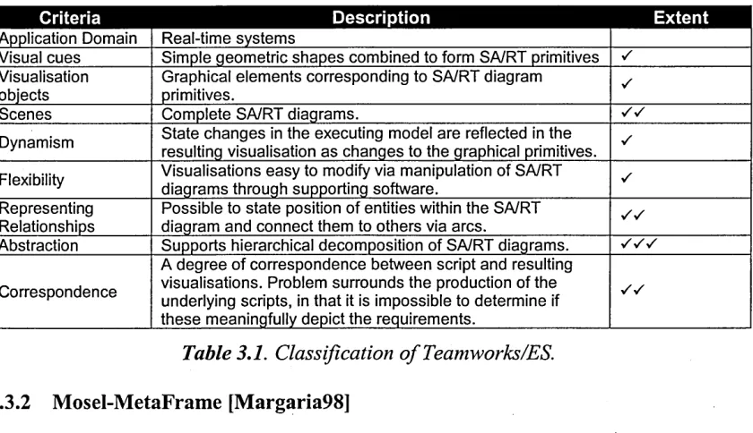
2.3.1 Teamwork/ES [Blumofe88]...42
2.3.2 Mosel-MetaFrame [Margaria98]... 43
2.3.3 ENVISAGER [Diaz-Gonzales87]... 45
2.3.4 Visualising Concurrent Z Specifications [Evans94]... 48
2.3.5 Visualising VDM Execution [Cooling94]...50
2.3.6 Problems with Existing Prototype Behaviour Visualisation Systems...52
2.4 Summary...54
Chapter 3 - An Alternative Prototype Execution Visualisation System 3.1 System Overview...57
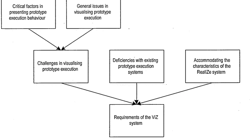
3.1.1 System Context...57
3.1.2 Requirements of the ViZ System... 62
3.1.3 ViZ System Characteristics and Capabilities...65
3.2 The ViZ Process... 67
3.2.1 Scenario Identification and Documentation...68
3.2.2 Visualisation Design and Construction... 72
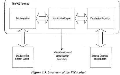
3.3 The ViZ Toolset... 77
3.3.1 Visualisation Provision...78
3.3.2 ZAL Integration... 82
3.3.3 Visualisation Engine... 84
3.4 Summary...86
Chapter 4 - Case Studies 4.1 Case Study - An Automatic Teller Machine...88
4.1.1 A im s...89
4.1.2 Context...89
4.1.3 Method...91
4.1.4 Results... 110
4.1.5 Observations and Conclusion... 112
4.2 Case Study - An Email System...114
4.2.1 Aim s... 114
4.2.2 Context...114
4.2.3 Method...116
4.2.4 Results...130
4.2.5 Observations and Conclusions...131
4.3 Case Study - A Water Level Monitoring System... 133
4.3.1 Aim s...133
4.3.2 Context...134
4.3.3 Method...141
4.3.4 Results...148
4.3.5 Observations and Conclusions...149
4.4 Case Study - A Security System... 155
4.4.1 Aim s...155
4.4.2 Context...155
4.4.3 Method...159
4.4.4 Results...166
4.4.5 Observations and Conclusion... 170
4.5 Summary...171
Chapter 5 - Critical Evaluation and Conclusion 5.1 Thesis Contributions Revisited...173
5.1.1 Survey of the State of the Art... 174
5.1.2 Development of a System to Visualise Prototype Execution...174
5.2 Evaluation Against the Original Research Objective... 182
5.3 Discussion...182
5.4 Opportunities for Future W ork...186
5.4.1 Enhancements to the ViZ System... 186
5.4.2 Further Research in Applying Visualisation to Requirements Prototyping... 188
5.5 Concluding Remarks...189
References and Bibliography... 191
Appendix A - System Specification Document... 205
Appendix B - ViZ Software Requirements Specification Document...213
Appendix C - Results of ATM Visual Prototype Execution... 225
Appendix D - Email System Formal Specification... 230
Chapter 1
Computing pervades nearly every facet of life in modem society. It is acknowledged that no single technology has impacted society as quickly or radically, or has brought such massive changes in the way lives are conducted. We are now at a point in history where computing and some societies are inextricably linked.
Computing can be partitioned into two distinct fields. The first is hardware technology. This comprises the electronics and machinery that provide the underlying processing and communication capabilities. The second field is that of software.
When viewed in simple terms software is an abstraction that enables us to exploit the ever-increasing power, speed and features of hardware devices. However, when viewed from a deeper human-centred perspective software becomes an enabling technology that allows us to enhance and extend our innate natural attributes and skills - it facilitates our creative abilities, enables us to control complicated processes or activities, and allows us to control devices that perform tasks which would otherwise be too dangerous or too complex to perform ourselves.
Since it is so useful and critical, the demand for software is great. Requests for new software increase annually, placing the onus on a global software development industry to implement progressively more innovative and complex software systems.
The high demand for software far outstrips supply, and the ability of the software development industry to supply it. Often software is delivered that does not perform as originally intended, is delivered later than initially expected, or exceeds its budget estimates. This problem, which in 1969 was termed “the software crisis” [Naur69], persists today and its effects have an impact on all modem societies and economies [Gibbs94]. Studies conducted by both industry and academia show that 31% of all new software development projects will be cancelled before completion, and that 52% of projects will suffer budgetary overruns [Standish98]. The reasons for such failure stem from the fact that developing software is a time-consuming, thought-intensive, and sometimes experimental activity, which often requires the effort of a large number of software developers.
experience from the industry, the continuously evolving discipline of Software
Engineering aims to provide such foundations [Pressman97].
Due to more than 30 years of software engineering research and application, it is now understood that the development of software follows a general ‘step-by-step’ process that consists of a series of interrelated activities. Firstly, the functions that are required of the new software are identified and documented. Secondly, the software is designed and implemented with a view to meeting these requirements. Thirdly, the software is tested to detect the presence of errors so that they are rectified before the final activities are performed - that of delivery and use. Subsequently, and as part of an on-going process, the software may be modified to meet changes to its requirements or its environment, or address errors not detected in the development stages. This pattern of software development can be characterised in the form of a ‘software lifecycle’ [Royce70]. A wide variety of lifecycles have been proposed to suit different software applications, eccentricities with development practices, or to accommodate organisational variations [Boehm88, Davis93], but still, it is widely accepted that these activities are essential in all software development projects.
It has emerged that one of the most pressing difficulties with software development, and one that has been identified as contributing greatly to the cause of erroneous or inadequate systems, and to the software crisis in general, is the first stage of the software life-cycle - that of ascertaining and securing the requirements of a new software application [Brooks87]. The umbrella term Requirements Engineering (RE) is used to encompass this early lifecycle activity [Royce70, Davis93, Dorfinan97, Swebok03]. It is during the ‘requirements engineering stage’ of the lifecycle, that the stakeholders (i.e. the individuals or groups with a vested interest in the software system, which include software engineers and developers, customers, users, investors, managers, etc.) converge in an attempt to define precisely what is required of the proposed software. The aim is to develop a view of the proposed system that is shared, agreed and understood by all involved [Faulk97]. The result of the requirements engineering stage is a document, or set of documents, known as a software requirements specification, that describes the features that the proposed software systems should possess.
is with this in mind that requirements engineering is the focus of the research presented in this thesis. The work aims to address a particular problem that can adversely affect the practical application of requirements engineering. The aim of this chapter is to introduce this work. An overview of the problem being addressed is provided, and subsequently, the specific objectives of the research and the scope of the research contributions are defined. Finally, the chapter will describe the structure of the remainder of the thesis.
1.1 Problem Definition and Research Proposal
Effective requirements engineering is dependent upon dialogue between the developer and customer being established and sustained. This is needed to facilitate discussion about the requirements, so that the customers can elucidate their needs, resolve uncertainties, or negotiate conflicting interests that may exist.
To assist in facilitating dialogue during the requirements stage, a notable and now popular technique has been developed. This technique is prototyping. It involves developing a mock-up of a proposed software system to illustrate its behaviour [Brook87]. Prototypes provide stakeholders with an opportunity to interact with the software, before it is fully developed, in a tangible way [Gomaa90, Sommerville97]. Importantly, prototypes become an instrument for stimulating dialogue between the developers and customers. By observing the execution behaviour of the prototype, stakeholders are able to see how a system, or part of it, will function when developed. This leads to discussion about the requirements, which in turn can be used to help resolve uncertainties or ambiguities with the requirements information, or uncover new requirements as the prototyping process progresses [Thebaut90].
Experience with prototyping has shown that its effectiveness in assisting the requirements engineering process is entirely dependent upon stakeholders understanding the prototype’s execution behaviour. As a prototype is executed, outputs, such as results from calculations, messages and other indicators of execution progress are generated and displayed.
outputs are presented using terminology, concepts or vocabulary with which the stakeholders are unfamiliar. One particular source of such vocabulary is the domain of software engineering. Developers prefer to use software engineering notations and terms to present prototype execution behaviour, as they are familiar with these and they offer the levels of precision and conciseness that developers require. However, whilst being of benefit to the developer, the use of such languages and terminologies when presenting prototype behaviour can adversely affect the ability of non-technical stakeholders to comprehend it [Cooling94], or as Davis, when describing the ability of a “computer-naive” customer to understand requirements specifications, states,
. understandability appears to be inversely proportional to the level o f complexity and formality.” [Davis88]. This presentation problem can affect the quality and richness of
the dialogue between the developers and customers, and importantly, the reliability and effectiveness of the whole requirements engineering stage.
The problem can occur irrespective of the display mechanisms used to show prototype execution behaviour. Some prototyping approaches rely on text-based display mechanisms. Whilst showing messages or calculation results, these offer little in the way of attempting to meet non-technical stakeholder’s needs in terms of their comprehension requirements. Other prototyping approaches base their displays upon more sophisticated representations. These approaches use graphical presentation techniques from the area of visualisation. The aim is to present information in ways that will initiate or promote understanding by drawing upon the potentially expressive nature of graphical representations. In favourable circumstances these offer much greater ‘bandwidth’ for portraying complex concepts or voluminous information than alternative textual forms [Myers88, Shu89]. Prototyping systems that employ visualisation techniques do so to amplify the comprehensibility of execution behaviour.
The utility, flexibility and potential that visualisation has to offer means that it remains a promising technique for presenting prototype execution behaviour. The flexibility and expressive power of graphical representations enable them to present a practically unlimited range of subject material, values, and results from any domain [Cooling94]. This research argues that these characteristics can be exploited by prototyping. The argument is that prototype execution behaviour can be presented using vocabulary and concepts other than those belonging to the domain of the software developer by using imagery that is borrowed directly from the stakeholders’ own domain [Parry95]. This will require techniques that enable the use of a rich repertoire of representations, i.e. representations that are based upon photo-quality images or diagrams, and graphical animation, to depict the imagery from the stakeholder’s domain. By employing such flexible and expressive display mechanisms, prototype execution behaviour can be portrayed in ways that non-technical stakeholders might be able to comprehend more readily.
It is proposed therefore, that this research should develop an alternative prototype execution visualisation approach that provides customer-oriented display mechanisms. The proposal is that this approach should differ from existing prototyping systems by making available visually rich display facilities. The objective is to develop a prototyping system that will be capable of presenting the results of executing prototypes in more customer-oriented forms.
1.2 Research Contribution
This research contributes to the field of requirements engineering, and more generally to the discipline of software engineering. In addition, by applying the principles and techniques of visualisation, a contribution to the field of visualisation is also made. The contributions are as follows:
2. The development of a system to visualise prototype execution. The system applies visualisation to a specific prototyping facility, and aims to do it in such a way that the general problems identified with existing systems are overcome. This particular contribution also includes the development of documentation that describes the system’s requirements.
3. Demonstration of the effectiveness of the system. This is achieved by applying the system to a set of case studies.
To summarise, this research provides a unique contribution to the field of requirements engineering by providing a novel approach to visualising prototype execution behaviour.
1.3 Thesis Structure
The thesis is divided into five chapters. The structure of these chapters and summaries of their content are given below.
Chapter 2
This chapter introduces the key areas that are the focus of the research. Firstly, requirements engineering is described. An overview is presented of its principles, products and processes. The description then focuses on a particularly popular and worthwhile requirements engineering technique, namely that of prototyping. Next, the problem that forms the motivation for this research is discussed which surrounds the problem of presenting prototype execution behaviour in a form that is comprehensible to stakeholders. At this point, the discipline of visualisation is described, including its principles and rationale, as a potential solution to the research problem.
Chapter 3
Chapter 3 presents the substantial contribution of the research. It describes the requirements and design for a system that overcomes the research problem stated in
Chapter 2. The Chapter is divided into three sections. The first presents an overview of the system. In this, the prototyping facility that is the focus for the application of visualisation is described followed by an abstract description of the system that presents its major components and general architecture. This comprises two facets, namely a process that provides step-by-step prescription of the activities required to undertake visualisation, and a software toolset that provides the actual visualisation capability. The second and third sections elaborate on the process and the toolset respectively.
Chapter 4
This chapter demonstrates the application of the system described in Chapter 3. This is done through the use of four case studies. Each one exemplifies a certain aspect of the visualisation system by following the development of a visual prototype for a target specification. First the informal requirements specification is given, followed by the enactment of the process. The results are then presented along with a conclusion.
Chapter 5
Chapter 2
The aim of this chapter is to describe the background and motivation for this research in detail. It describes a number of areas that are of particular concern and that provide context for the work. Moreover, the specific problem that the work addresses is elaborated in full.
The chapter is structured into four sections. The first section describes the area of requirements engineering, and prototyping in detail, to provide a background for the work. The second section concentrates upon the specific issue of presenting prototype execution behaviour and the problems inherent in this. In so doing, this section frames the work by introducing visualisation as a means to facilitate prototype behaviour visualisation: The third section presents a literature survey that reviews existing approaches in the field of prototype execution visualisation, from which general shortcomings and disadvantages are identified. The fourth and final section in this chapter offers a summary that indicates the specific objectives of the research, namely to develop an alternative prototype execution visualisation system that overcomes the problems identified with the existing approaches.
2.1 Requirements Engineering
Software is developed in response to the needs of organisations, governments and general market forces. To implement software that will satisfy the needs of these ‘customers’, software developers must first ascertain exactly what is required. The activity known as requirements engineering is conducted in aid of this.
The critical nature of requirements engineering cannot be stressed sufficiently. It forms the foundation of a software development project by providing knowledge about the customer’s needs. This knowledge will be used in all major decision-making and design activities throughout the project [Diaz-Gonzales87]. The importance and need for RE is such that it is recognised throughout industry and academia. It is a stated requirement in major software engineering standards, process improvement schemes and good practice guides [Paulk93, Spice03, TickltOl, Swebok03], and is found in most (if not all) software engineering curricula and subject benchmarks used in education world-wide [SEI03, QAA03, ACM03].
proclaiming so. For example, Brooks, in 1987 stated “The hardest single part o f building a software system is deciding precisely what to build. No other part o f the conceptual work is as difficult as establishing the detailed technical requirements...”
[Brooks87], and more recently, Potts claimed “[it] remains one of the most challenging areas for software developers” [Potts94]. A variety of problems can impede its effectiveness, leading to errors in the resulting descriptions of the proposed software system. These problems include:
• Establishing an understanding of customer needs early in the software development lifecycle [Faulk97].
• Difficulties in exploring customer needs and helping customers identify what they want [McConnell03].
• Distinguishing and recording what the software should do, as opposed to how it should be built [Davis88, Swartout82].
• Problems of scale, and the inherent difficulties of gathering accurate requirements for large systems that typically involve large numbers of users and developers [Faulk97, Thebaut90].
• Communicating requirements to different, but relevant audiences, and in ways they can be understood by these audiences [Stephens93].
- • Managing changes in requirements as a software development project progresses [Scharer81].
If errors are manifest in the requirements specification, they will propagate throughout the entire project, crippling it. Moreover, the effects of these errors often reach beyond the bounds of the software’s functionality. It is widely observed that the later an error or an omission is detected, the more expensive it will be to repair [Alford77, Boehm81, Davis93]. In addition, software that is flawed or does not perform as the users expect, as the result of an inaccurate or erroneous specification, will be ill received or may not be used at all. Much evidence exists to support these observations [Boehm76, Daly77,
/
Requirements engineering can be viewed from two perspectives, namely product and
process. The product is the document, the software requirements specification, which states the desired functionality and other characteristics of the software. The process is the collection of requirements-oriented activities that, when performed, contribute to the delivery of the requirements specification. These two aspects will be described in detail below.
2.1.1 The Product of Requirements Engineering
The product of the requirements engineering stage is a document, or set of documents, known as a software requirements specification (SRS). The SRS has several roles during, and after, a software development project, including:
• Providing a point of reference for the developers and other stakeholders by stating the functionality of the software system. It is important that this functionality should only state ‘what’ the software should do, and not describe ‘how’ the software should be implemented, as this may restrict the developer’s choice of possible solutions [Scharer81, IEEE98a].
• Acting as a focal point for communicating, circulating, and exchanging ideas and information about the software.
• Forming part of a contractual agreement between the customer and developer [Zave90].
• Serving as the basis for project costs calculation and scheduling [Dorfman97].
• It may be used in the testing and maintenance stages in the context of providing details of what the software should do and what functionality was originally decided.
To fulfil these roles effectively, the SRS should represent a statement of all the characteristics of the software system. These characteristics can be partitioned into three fundamental categories [Davis93, Sommerville97, KotonyaOO]:
• The constraints placed upon the system. These define what the software should not do, which includes its bounds, and any environmental quantities (such as laws or standards) that place limitations on the software.
• Any non-functional requirements. These define non-behavioural aspects of the software, i.e. attributes of the system as it performs its prescribed activities. For example, non-functional requirements state the system’s desired level of efficiency, performance, and maintainability.
Of importance is the means by which requirements specifications are documented. Much work by the software engineering and requirements engineering communities has gone into developing notations with which requirements can be expressed. As such, a wide variety of notations exist, each offering varying features and different levels of formality and abstraction to facilitate the definition of a specification that possesses the attributes described above. They can be partitioned into two major classes: textual and
graphical.
Textual representations are a seemingly obvious choice for expressing requirements. One such notation is that of natural language. This is due to the richness and expressiveness of general vocabulary. However, reliance on natural language specifications is one of the main sources of ambiguity, and hence difficulty [Pamas77, Meyer85]. Natural language is verbose in nature, which enables the incorporation of irrelevant information, and sometime results in unnecessarily long documents. It is also ineffective at decomposing and structuring requirements. The use of mathematically based specification languages has been advocated as an alternative [Pamas77, Hayes86, Jones90]. These languages are based upon mathematical formalisms and concepts that make it possible to concisely and unambiguously express requirements [Vienneau97].
that a system can be found in and the possible transitions between these states [Pamas69]; Petri-nets are diagrams that are used to specify process synchrony during the design of time critical applications and are represented as directed graphs augmented with tokens [Petri62, Peterson81]; and a variety of notations (and associated methods) designed for analysis and specification, including the Entity-Relationship Diagram (E-R Diagram) [Chen76], Structured Analysis and Design Technique (SADT) [Marca88, Ross77] and SSADM (Structured Systems Analysis and Design Methodology) [Weaver98]. Finally, the Unified Modelling Language (UML) [Booch99] offers a comprehensive graphical approach to specify designs for systems in object-oriented terms.
2.1.2 The Requirements Engineering Process
In attempting to produce an SRS, it is essential that a defined and systematic approach be taken. Without discipline and diligence, and a defined set of activities to guide the developer, the delivery of an accurate SRS cannot be guaranteed. To this end, a general process of requirements engineering has been established that consists of three fundamental and interrelated activities, namely elicitation, analysis and definition and
validation.
Requirements elicitation is concerned with acquiring and establishing the nature, features and boundaries of a software system. The product of requirements elicitation, is a collection of knowledge that may or may not be structured or refined. The activity of elicitation can be thought of as knowledge transfer from a source (a person, document, etc) to the software developer.
After elicitation, the developer possesses a potentially large collection of raw knowledge about the proposed system. In this state, the information may not be in a form suitable for subsequent development - there may be inconsistencies, ambiguities and redundancies that could complicate and impede the project. Such undesirable qualities must be reduced or eliminated, and the results formulated into a useful software requirements specification. The activity of requirements analysis and definition serves this purpose. In analysis, the raw requirements details are sorted and refined, and redundancies discarded. In specification, the refined information is structured in the form of an SRS.
The SRS represents the developer’s view of the requirements. It is produced from the developer’s understanding of the proposed system, which in turn is formulated from the information gathered during the elicitation stage. Consequently, it is essential to judge whether this view matches the customer’s original requests and that no errors have been introduced along the way or that no omissions exist. Validation embodies this activity [Fuji97, Lalioti93, Sommerville97].
From the developer’s point of view, validation seeks to answer the question “are we building the right product?” [Boehm84]. From the customer’s point of view, validation can be thought of as an activity that builds confidence into the product. Validation of the SRS entails customers and developers evaluating requirements details, identifying potential errors or omissions, and negotiating and resolving emerging conflicts. These are complex, asynchronous and communication-rich activities, which importantly, require effective dialogue to be established and sustained between the parties concerned. To this end, a variety of requirements validation techniques have been developed [Fujii97]. Each offers varying level of support for establishing and sustaining dialogue.
to read, and at worst, they may be unable to comprehend its contents at all, especially if it has been written with developers in mind [Gomaa90, T*hebaut90]. This is echoed by Dorfman, who observes “Requirements documents and specifications cannot easily be read by users.” [Dorfman90].
An alternative to this basic approach to validation can be found in ‘goal-oriented’ requirements engineering techniques. A goal is “an objective the system under consideration should achieve” [Zave97]. The goal-oriented approach can be useful in enabling users to express requirements. Customers can often articulate what they want to do with a system, but cannot give detailed breakdowns of the requirements that will enable them to satisfy these needs. Therefore, goals are used as the basis for discussion and investigation. It should be noted however, that goals are not requirements in themselves; they are abstract descriptions of what the system should do, which may require more than one requirement to fulfil [LamsweerdeOl]. Goal-oriented requirements engineering has stimulated a number of methods and tools, including the notable KAOS system [Lamsweerde95] and the related GRAIL approach [Bertrand97].
Another validation approach is that of scenarios. Scenarios are descriptions of examples of system usage [Weidenhaupt98]. They provide a means of describing the activities that comprise the software’s functionality and the situations in which the system will be used. Scenarios used in this context are known as descriptive scenarios [Potts94, Rolland98]. Scenarios can also provide a framework for asking questions about the user’s tasks and how a system should facilitate such tasks [Rumbaugh94], i.e. questions concerning “how is this done?” or “what if...?” and as such provide an opportunity for requirements elicitation and validation by stimulating and facilitating discussion [Hooper82, Potts94, Heymans98, Sutcliffe98]. Scenarios are gaining much popularity within the requirements engineering community. This is evident by the development of a wide range of tool support and methodological assistance [Filipidou98, Rolland98]. However, it should be noted that scenarios are not complete requirements specifications. Scenario descriptions provide details of only instances of system use, whereas a requirements specification describes the system in general terms.
prototyping. Its aim is to enable customers to play a direct and involved role in the requirements process, by enabling them to see and interact with a model of the requirements, and is described next.
2.1.3 Requirements Prototyping
Prototyping is a well-known and popular requirements engineering approach. The activity involves the development of an executable model of the requirements (or part thereof) that the stakeholders of a software development project can use to experiment on and evaluate ideas with. The aim is to enable the stakeholders to assess the accuracy of the requirements gathered so far, as well as to evaluate each other’s understanding. [Brooks87, Luqi89, Gomaa90]. To this end, prototyping embodies the activities of requirements elicitation and validation.
The activity of requirements prototyping mirrors its traditional industrial/engineering counterpart, whereby a prototype is developed and used to demonstrate or investigate the intended features of a product or a manufacturing process before full-scale manufacturing takes place. For software, prototyping comprises an ‘evaluate then modify’ strategy [Davis92] that is repeated until it is agreed that the prototype reflects the functionality required in the proposed product or that sufficient information about the product’s features have been discerned.
For our purposes, the objectives and advantages of prototyping are synthesised as follows:
• To stimulate and sustain dialogue between developers and other stakeholders during requirements validation [Gomaa83].
• To encourage stakeholder participation in the process, and at an early stage of the production process [Gomaa90, Carey90].
• To assist in problem analysis by providing an opportunity for uncovering and understanding the details of the proposed system [Hardgrave93].
Due to its inherent flexibility, it is not surprising that variations of the prototyping process have been developed to accommodate different types of software development projects and the differences in the strength or level of understanding of requirements [Davis92]. One variation is the ‘paper prototype’ [Thompson92], where an impression of how the software will look and behave is created with paper-based documentation.
Another variant is that of ‘evolutionary prototyping’. This approach involves the implementation of a small set of well-understood requirements in order to provide a solid foundation, with additional functionality being appended as the process progresses. During subsequent iterations of this prototyping process, further requirements are revealed or clarified, and correspondingly implemented on top of the existing system [Hekmatpour88, Luqi89, Davis93]. In this approach, the prototype is developed and refined in a quality manner, using quality implementation techniques and tools. Such prototypes embody quality architectural-, performance- and exception handling characteristics.
Lastly, there is the discardable model. This is a prototype that is metaphorically ‘thrown away’ once sufficient understanding of the requirements has been generated. The experience and knowledge gained during the process contributes to completing the SRS [Gomaa86]. In this approach, the prototype need not be a flawless implementation or offer the same performance as a full-scale production-quality system [Brooks87]. In addition, such a prototype need not model all the requirements of the proposed system. It need only focus upon issues that are believed to require exploration or further clarification. These prototypes can be constructed in a variety of ways, including the use of conventional programming languages, fourth generation database tools, or executable formal specification languages. In addition, specialist prototyping environments or workbenches that facilitate rapid application development can be used [Hekmatpour88].
regarding requirements, and be instrumental in eliminating developer’s misconceptions or clarifying assumptions. From the developers perspective, they must be given the continuous opportunity to clarify and enhance their understanding of the requirements, and resolve ambiguities, contradictions, or fuzziness in the requirements details. Both parties must be given the opportunity to evaluate arid review requirements details as they emerge, in order to stem errors that could propagate into the subsequent development. These activities require a ‘communication rich’ environment where dialogue is continuous. Such an environment can be stimulated and sustained by employing prototyping [Carey90].
Prototyping facilitates and sustains dialogue by regarding the prototype as the focal point of any discussion. Interaction with, and evaluation of the prototype stimulates discussion about its features. Customers can judge, assess, and then discuss its functional accuracy, and subsequently contribute additional materials or provide clarification where necessary. Moreover, developers can use it as the basis to discuss the requirements the prototype represents and use it as a framework to guide them through the discussions about any fuzziness in their understanding. Both parties can evaluate the prototype against their own perceptions of the requirements. They can also evaluate the perceptions of the other party and gauge their reactions during the discussions. These interactions provide customers and developers with the opportunity to express approval or dissatisfaction with an aspect of the prototype, or discuss potential omissions.
As a result of the interaction and dialogue, developers become more aware of the customer’s needs. They can validate their newfound knowledge by modifying the prototype to reflect their understanding of the requirements. This process iterates until both parties are confident that sufficient detail about the requirements has been established. This cycle, of evaluate then modify, enables the requirements knowledge to be refined with respect to time. In some forms of prototyping (such as ‘throwaway’ forms), this time may be quite short, with modifications being made to the prototype almost continuously, whereas in others (i.e. ‘evolutionary’ forms), the modifications occur over a longer timeframe and in a quality manner, whereby the prototype is grown into a more mature product.
and techniques, as is the case with throwaway variants or the prototype is used by the customers in the same way as a full scale production-quality system would be, until more functionality is added.
2.2 Presenting Prototype Execution Behaviour
The opportunities for iteration and communication offered through prototyping have made it a useful technique that has been applied, in its various forms, to a great number of software development projects. Its popularity and adoption within industry, and its study within academia, illustrates its usefulness and importance. However, a variety of issues and problems can effect the successful application of prototyping. These problems include problems of a technical and managerial nature, such as determining when to conclude the prototyping process, how to control and update the documentation that the process can generate, and how the stakeholders can be reassured that the prototype is not the full working system.
Of particular importance is a problem that can adversely affect what is arguably prototyping’s greatest strength - its potential to stimulate, sustain and enrich the communication between stakeholders about the requirements of a proposed software system. This problem is that of presenting the prototype’s execution behaviour to stakeholders effectively. Prototype behaviour is generally presented as the results, messages, or inputs/outputs that are generated from the prototype’s execution. If for any reason, these results are not presented in a manner that the stakeholders can understand during evaluation of the prototype, validation of the requirements that the prototype represents then becomes uncertain and unreliable. This is because stakeholders will not be able to make a reasoned assessment of it [Parry95, Ozcan98a].
2.2.1 Critical Factors in Presenting Prototype Execution Behaviour
The critical problem of presenting prototype execution behaviour in a way that is comprehensible to stakeholders during the validation process is symptomatic of a combination of several interrelated issues, namely support, presentation, developer attitudes, development costs, and the inherent differences between developers and other stakeholders.
Support concerns the presentation facilities that are available in the tools, languages and workbenches that facilitate prototype implementation and execution. It is evident that many of these simply do not offer comprehensive support for presenting prototype execution, especially those that facilitate the development and exploitation of throwaway prototype variants. Many prototype implementation approaches shun comprehensive presentation techniques in favour of providing focused and productive prototype development environments. In addition, these approaches usually accompany specialist notations that are used to express prototype behaviour. Such notations are often abstract, in that they obviate the need to specify behaviour in low-level terms. This abstraction also displaces comprehensive display features in favour of general, and often minimal, display and user-interface facilities. While being of benefit to the developer, these abstract or minimal presentation techniques limit the range of representations with which prototype behaviour can be presented. The types of representations usually range from minimal text based outputs to rudimentary diagrams. However, in many cases the only representations offered are based upon the concepts, terminologies and vocabularies used by developers, i.e. those belonging to the domain of software engineering. It is unreasonable to expect customers to learn and understand such regimes, which in turn, leads to the situation where customers do not comprehend the prototype behaviours that are presented to them [Lalioti93]. This factor is directly related to next factor, presentation.
they are able to accommodate a variety of stakeholder types and domain characteristics, and deliver displays that can be tailored to suit their needs so they can comprehend the underlying requirements successfully. If however, prototyping approaches do not offer suitably rich and flexible display mechanisms the representations used will not portray the prototype’s execution in ways that suit the stakeholders and hence, in ways they will understand. This can seriously impede the overall effectiveness of the prototyping approach.
In addition, effective presentation is not just dependent upon varied and flexible representation types. It also relies upon showing execution behaviour in meaningful and unambiguous terms so it is not misinterpreted or misunderstood by stakeholders [ParryOO]. In other words, representations must adhere to the concept of ‘what you see is what it means’ (WYSIWIM).
Developer attitudes concern the preferences of developers when producing and using prototypes. Developers often prefer to use technically oriented terms with which to present prototype execution behaviour. They might not wish to use different, less technical or less precise notations during the process. Instead, they are likely to be very familiar with such representations as they may well have extensive practical experience in using them. This has a direct influence on the types and styles of the representation chosen to depict prototype behaviour.
Development costs concern the financial cost, time and effort required to develop prototypes with comprehensive presentation characteristics. To reduce cost and effort, a developer may chose not to implement fully functional customer-oriented user interfaces that employ rich presentation techniques. User interfaces can consume much development effort - it has been suggested that they can take between 30% to 80% of the effort of developing a software system [Myers92, Remington97]. This particular point is pertinent to throwaway prototyping applications where the investment in terms of time and costs may never be recovered.
developer understands the domain of software engineering and its associated languages, terminologies and concepts, and on the other, stakeholders understand their own domain, their working environment, and the activities that are associated with their domain. Additionally, when discussing or describing their domain, each group often prefers to use their own terminologies, vocabulary, and shortcuts. Due to these differences, a ‘comprehension gap’ may emerge between the parties involved. This creates an invisible barrier between them. Whilst not immediately apparent, such differences will produce cultural and technical divides that will affect communication. Customers may feel ignored due to a lack of participation in the process, feel they may be unable (and subsequently unwilling) to articulate their needs to the developer, or feel that the developer does not (or is unwilling) to understand them and see their point of view. Developers may feel insecure about the software they are developing as they may lack confidence in the requirements that are emerging, or they may have little faith in the customer’s ability to communicate their desires. These points can affect developer morale and the eventual success of the project.
Although proponents of prototyping claim that it is possible to overcome the problems that stem from these factors, in practice it is found that they still manifest themselves in the prototyping approaches in use today. This renders many ineffective at depicting prototype execution behaviour in ways that all stakeholders can recognise and comprehend.
2.2.2 Applying Visualisation to Present Prototype Execution Behaviour
As a way of overcoming some of the difficulties that are inherent with presenting prototype execution behaviour, the application of the technique of visualisation has been advocated [Cooling94, Parry95]. Visualisation is an activity that involves presenting information using visual representations, i.e. representations that utilise the power of computer graphics. The aim is to exploit the power of visual representations to amplify the comprehensibility of information. To this end, visualisation can be viewed as a tool that can be used in situations where the inherent expressive power of visual representation might be leveraged against presentation problems.
The rationale for applying visualisation to prototyping rests upon its potential to assist in stimulating communication between the customer and developer. Through visualisation, visual images, based on visually rich and flexible displays techniques, can be used to portray execution information in terms borrowed directly from the customer’s own domain with which they are familiar. If the customer is able to comprehend the execution behaviour through such appropriate images, then they will be able to make reasoned comparisons between their own perceptions and what they see, or identify omissions in what is presented to them. Subsequently, they will be able to discuss the differences or omissions that they recognise with the developer. The communication in this visualisation-assisted prototyping process is likely to be effective and productive.
Visualisation is beneficial to both the developer and customer. From the developer’s perspective, confidence in the project can be built on the knowledge that the requirements are an accurate reflection of customer’s needs. Confidence breeds motivation, and in turn, results in higher probability that the project will be a success. Such benefits accrue from a successful requirements engineering process, which can occur if supported by effective communication through visualisation. Customers can feel confident and content that they have played a role in the development process. They see progress, and they see specifications that more accurately document their needs.
older text-based displays as the primary form of computer output. This is evident by powerful high-resolution user-interfaces and use of photo-realistic images that pervade every facet of computer use today.
Mass adoption of such technology has enabled graphical presentation techniques to be harnessed and exploited to portray the results that emerge from applications. These efforts are driven by knowledge that presenting information graphically, in many circumstances, offers a greater degree of flexibility, abstraction and expression, than is offered by text-based displays. These characteristics, coupled with advancements in technology, and the need to alleviate problems with existing output methods, have led to development of visualisation [Frenkel88, SpenceOl].
The origins of visualisation stem from the need to display increasingly complex and voluminous information. Traditional display methods, as used through the 1960s and 1970s, were limited in their scope, with output often restricted to rudimentary one dimensional text streams. Visualisation provides the techniques necessary to alleviate these presentation problems by presenting information visually.
Visualisation is not merely an alternative display technique, however. When applied effectively it allows information to be portrayed in ways to directly promote or amplify comprehension. It enables values to not just be ‘seen’, but instead, it allows insights to be gained, perhaps by enabling relationships between data to be discerned, by enabling patterns from complex arrangements of information to be extracted, or by presenting information in forms that accommodate the viewer’s ‘visual requirements’ [Gershon98].
Much has been documented about the superiority of graphical representations over textual ones in certain circumstances. Many authors make claims or discuss observations about the characteristics of presenting information visually and how this facilitates and promotes comprehension. For example, Stasko claims, “the two-dimensional format o f a picture can provide greater amounts o f relevant information more fluently than a stream o f text” [Stasko92], and Barrett states “pictures leave a more lasting impression that words alone” [Barrett94]. With another similar claim, Nan Shu argues that ''’’pictures can help understanding and remembering” [Shu89].
application is that of representing the complexity inherent in information [SpenceOl]. Certain types of visual representations, e.g. diagrams and charts, can be effective at expressing situations that would otherwise challenge the abilities of textually-based offerings. For example, Larkin [Larkin87] provides a good example of the contrast between visual and textual representations by presenting a problem concerning the arrangement of a pulley assembly. It is obvious from the representation that Larkin uses that the arrangement can be easily and instantly discerned, whereas if a textually based representation is used, the complexity exceeds the level by which it is possible to instantly and accurately imagine the assembly. In addition, Cox claims “In general, pictures provide a better representation for most complex structures...” [Cox89]. This
may be attributable to the size of the mind’s working memory, or the ability of an individual to understand a scene and conceptually derive a mental image of it.
A particular advantage of visual representations is that they may provide a way of alleviating certain communication problems [Camara94]. For example, pictures can be used to express thoughts without the use of text/language and overcome some cultural differences, or as Nan Shu states, “ When properly designed, pictures can be understood by people regardless o f what language they speak.” [Shu89]. This is evidenced by the proliferation of internationally recognised symbols and icons, such as road signs or the ‘Hazchem’ scheme used to indicate hazardous chemicals [TSOOl].
While presenting voluminous data in a visual form is an effective application for visualisation, the same techniques can be applied in different ways to support the visualisation of other types of information. Visualisation is often used to facilitate the direct display of representations. This type of application includes the visualisation of software (i.e. source code, and object code that is under execution) to render it in a more comprehensible form for developers [Myers88, Green91, ReissOl]. This is especially useful for the development and maintenance of concurrent software [Pillet95]. Other aspects of software and its development process can also be visualised, for example software architectures (i.e. module interdependencies, and object-oriented relationships) [Carr95, Feijs98, Booch99]. Computer-based applications can themselves be visualised, for example, visualising the contents of databases for the purpose of information retrieval [Combs92, Walton94]. The topology of communication networks and the volume and direction of network traffic also lend themselves to visualisation [Martin93]. Lastly, visualisation has been applied to illustrating the structure of the World Wide Web and the relationships that exists between Hypertext documents [Benford97].
Visualisation has also been extended to cover other domains. For example, visualisation has been used to depict the use and structure of natural language [Narayanan95]. It is also claimed that visualisation can play a major role in teaching, whereby complex concepts can be presented as diagrams to pupils and students [Dobson94].
In traditional visualisation systems, such as those that facilitate scientific, mathematical or volume visualisation, the transformation processes that underpin them are encapsulated in a set of rules that state how the source representation will be re presented. The rules would state how to process and analyse the source representation or source information, which visual representations to apply, and how to render these on a chosen display.
In contrast to the technical details of how visualisation is performed, an important issue, and one that has profound significance to visualisation, is interpretation. Interpretation is a pertinent issue in many domains, such as art, law, and philosophy. It is necessary therefore to define its scope and meaning in the context of visualisation, and more specifically to this research, to its relevance.
In terms of visualisation, interpretation, or more specifically, the act of interpreting a visual representation, refers to a transaction between content and a viewer. This transaction, concerning the determination of meaning from the source, is conducted through a visual representation that portrays the content in a way that its designer/creator deemed appropriate. The transaction is thought of as being successful if the viewer accurately determines the knowledge as intended, from its representation.
A successful transaction depends upon two conditions. The first is that the representation must be appropriate at portraying the knowledge, i.e. its appearance is suggestive, indicative or directly corresponds to the knowledge concerned. In some cases, to accommodate a particular viewer type, the representation must be composed of visual cues with which a viewer is familiar. The second is that the viewer must be able to understand the representation sufficiently to ascertain the knowledge it attempts to convey. The viewer may require a certain level of knowledge or experience to understand a representation. For example, the viewer may have to understand a vocabulary of symbols, or be capable of reading a particular diagram or chart. If these conditions are not satisfied, the representation may be misinterpreted, resulting in the viewer determining an incorrect, or a partially correct perception of the knowledge.
given representation into one based upon graphical forms, that is able to convey the underlying knowledge in a manner that reduces the potential for misinterpretation and promotes viewer understanding.
2.2.3 Challenges in Visualising Prototype Execution Behaviour
A variety of fundamental challenges confront the application of visualisation to presenting the behaviour of prototype execution. These challenges can be divided into two sets. The first involves human factors challenges that pertain to cognition and comprehension of visualisations, and the second involves the technical and practical
aspects of visualising prototype execution behaviour.
Human factors pose fundamental and profound challenges. The first of these involves understanding how visualisations are indeed useful and how appropriate information can be imparted, and subsequently comprehended by a viewer. Understanding this can form a way to assist in building effective visualisations. Humans possess a powerful image acquisition and processing system, the anatomy of which is well known. However, problems begin to arise when a deeper understanding of what happens to an image after it has been captured is required, as the precise reasons for the way meaning can be grasped by ‘seeing’ a visual representation are not entirely understood. Some of the more general ideas that have been postulated by various authors about image comprehension will be highlighted.
constituent parts. Each part is processed, with meaning attributed to each part (based upon comparisons to existing patterns or images in memory) in parallel, resulting in a real time mechanism that facilitates comprehension.
In contrast to the component-view, there is the overall or ‘synthesised-view’ of a how an image is understood, or in other words, how the whole representation conveys meaning. It is argued that to understand a text-based representation, a reader must focus upon each word and understand it [Petre90]. There is a temporal issue here, which dictates that to understand a sentence, the entire set of words must be read in their correct sequence, whereby each word’s meaning must be retained then pieced together. Visual representations on the other hand do not suffer from this, as they can be ‘scanned’ quickly, and the whole image can be ‘absorbed’ [Petre90]. Converting large data sets into visually represented models therefore greatly assists in its rapid comprehension [Webster90]. However, to gain an overall understanding of a large set of data, if viewed by textual means, each data item would need to be read and understood.
The next human factors challenge progresses to understanding how the visual processing system in humans is able to understand the image characteristics. Humans excel at acquiring and processing visual imagery. They achieve this by invoking the highly developed visual processing system that comprises the eye, the optic nerves, and the visual cortex [Valeric03]. Anatomically, these areas are well known, but modem medical science cannot fully explain how these bodily components combine to provide the image capture and recognition system inherent in humans. Despite this fact, many authors have stated claims about the observable capabilities of the human visual processing system. For example, many authors have commented on the perceptual endowments of people and that they are strongly optimised for real-time image processing [Duisberg87, Myers88]. Other authors comment on the ‘bandwidth’ of the eye-brain combination and how it is the most powerful human communication channel, for example [Webster90], and that it is especially efficient when applied to analysing pictorial information. For a more in-depth treatment of the visual abilities of humans, refer to [Sekuler94, Humphreys89].
which is connected to the higher brain centres responsible for memory and consciousness [Hung02]. However, the reasons behind the ability of humans to understand, recognise, and interpret such visual information is not understood, although many theories have been proposed. Many centre upon the development of ‘mental- models’ of the world, and how certain visual images correspond more closely to these models [Cox89, SpenceOl]. However, such imagery also affects how mental models are interpreted. It is also claimed “the way a problem is represented has a strong influence on whether we can understand and solve it” [Bocker86]. Indeed, many great scientists have stated that they do not “think in words” as observed by Larkin [Larkin87] and that many problem solvers prefer a diagrammatic approach. This lends more credence to the notion of mental models, how mental models are developed, and how comprehension may stem from such models. Another aspect of image comprehension is the process that is invoked within the brain. The perception of spatial relationships and the discovery of patterns activate a series of mental processes. Evidence indicates that these are different to the mental processes invoked when a viewer reads text-based representations [Domik93]. This suggests that visual and textual comprehension is handled by different brain areas and are processed in different ways. For a more detailed investigation into the cognitive aspects of understanding visual representations refer to [Marr82, Spoehr82].
The technical challenges in providing visualisation facilities are as follows. Some of the major concerns that accompany each challenge are also discussed to provide additional insight into how the challenge may be satisfied, or what is required to overcome the problems that the challenge presents.
made in cost/training will not be wasted. To fully exploit the use of these existing tools or retain their usefulness in the future, it would be necessary to augment them with visualisation technologies, possibly via the use of a separate visualisation system. In these cases, it would be imperative for the visualisation system to inter-operate with the prototyping environment, so visualisations could be applied to the execution results.
The second technical challenge is to embrace presentation technologies and techniques that will both enhance the depiction of outputs f