International Journal for Research in Applied Science & Engineering Technology (IJRASET)
ISSN: 2321-9653; IC Value: 45.98; SJ Impact Factor: 6.887 Volume 6 Issue VII, July 2018- Available at www.ijraset.com
298
©IJRASET: All Rights are Reserved
Performance Evaluation Of IPSec Key Exchange
Protocol through Simulation
S. Sasikala1, A. Mohamed Nazeer2
1, 2
Lecturer, Electrical and Electronics Engineering, PSG Polytechnic College, Coimbatore
Abstract: A secure connection between two hosts in an Internet, Intranet must perform authentication of each endpoint, transport data reliably, protect against tampering or modification of data in transit. The Internet Protocol Security (IPSec) is a standard suite of protocol designed by IETF to provide security for IPv4 and IPv6. IPSec has three sub protocols, namely, Authentication Header (AH), Encapsulating Security Payload (ESP) and Internet Key Exchange (IKE) Protocol. This Paper deals about the performance evaluation of Internet Key Exchange Protocol (IKE v1), heart of IPSec, as it controls the services to be offered to secure the traffic and also manages the range of different transform options. Creation and management of Security Association (SA) are fundamental to the working of IKE and IPSec. The performance of SA at Phase1 and Phase2 is analyzed based on the Packet Size, Bandwidth. The performance measurement parameters include initial SA delay, rekey SA delay of IKE and IPSec. The impact of bandwidth consumption for the average of created SAs ,the delay of creation of SAs and the size of packet exchanged between the different security gateways are simulated and analyzed.
Index Terms: IPSec Performance, IKE, Internet Security
I. INTRODUCTION
Public and Private networks are susceptible to an unauthorized monitoring and access. Networks are often subjected to an attack. Some attacks are passive, meaning that information is monitored. Others are active, meaning that the information is altered with intent to corrupt or destroy the data or the network itself. Networks and data are vulnerable to attacks [20] such as Eavesdropping , Identity Spoofing ,Data Modification ,Password-Based Attacks, Denial-of-Service Attack, Man-in-the-Middle Attack, Sniffer Attack, Application-Layer Attack if no security plan in place. Computer networks are utilized for sharing services and resources. Information traveling across a shared IP-based network, such as the Internet, could be exposed to many devious acts such as eavesdropping, forgery and manipulation. So information need to be sent in a secure manner to the trusted receiver. IP-based networks divides data into packets and the independent routing of packets through a large network with no central control. Each packet is marked with its sender and receiver, the packets are not invisible to other devices on the network. An intermediate network device can easily intercept and examine any passing packet. This property of IP-based networks creates several potential security problems.
The Internet Protocol suite [17] provides no security at all. Security protocols can be utilized on all layers in the protocol suite to protect data in different ways. Designers proved that the IP layer is a good place to secure the data being communicated. Reasons are the IP layer is at the choke point of Internet communication can capture all packets sent from the higher-layer protocols and applications and all packets received by the layer network protocols. Security provided at this layer is independent of lower-layer protocols. Security provided at this lower-layer can be made transparent to the higher-lower-layer protocols and applications. Many application environments can benefit from security provided at the IP layer. The Internet Protocol Security (IPSec) suite [6] [7] to provide network security services such as confidentiality, data origin authentication, data integrity and anti-replay to protect datagrams in the Internet. Internet Key Exchange (IKE) is one major component in IPSec which deals Key Management [14] [15] [18] aspects. IKE allows communicating entities to derive session keys for secure communication via a series of exchange of messages. This work deals about performance of IKE v1. Due to scalability and practical implementation considerations, automatic key management seems a natural choice for exchange of messages in significantly large Virtual Private Networks (VPNs).
II. INTERNET PROTOCOL SECURITY
299
[image:2.612.69.534.89.242.2]©IJRASET: All Rights are Reserved
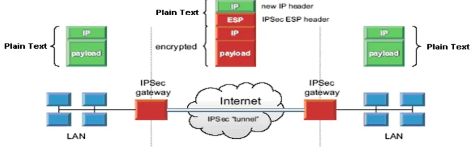
[image:2.612.82.531.338.451.2]Fig. 1 VPN using IPSec
Fig. 2 shows the IPSec Components. It has two core protocols, namely, IPSec protocols, Internet Key Exchange protocol. The IPSec protocols are the protocols used to protect the actual traffic being passed through the VPN. The actual protocols used, and the keys used with them are negotiated by IKE. There are two protocols associated with IPSec, namely, AH and ESP.
Fig. 2 IPSec Protocols and Components
The Internet Key Exchange protocol [3] [4] is a key management protocol standard that is used in conjunction with the IPsec standard. It is a hybrid protocol that integrates the Internet Security Association and Key Management Protocol (ISAKMP) [11], Secure Key Exchange Mechanism (SKEME) [3] [11], Photuris, and a subset of the Oakley key exchange scheme [11]. The purpose of IKE is to allow devices to exchange information required for secure communication. IKE provides authentication of the IPSec peers, negotiates IPSec keys, and negotiates IPSec security associations. It is an IPSec automated key management protocol. IKE eliminates the need to manually specify all the IPSec security parameters. The Ike Functions are to Provide a means for the endpoints to authenticate each other, establish new IPsec connections and manage existing connections. The process of negotiating session parameters consists of a number of phases and modes. IKE parameters such as Tunnel / Transport mode, Main/Aggressive Mode, IPSec Protocols IKE Encryption, IKE Authentication, IKE Diffie-Hellman Group, IKE Lifetime, IPSec Encryption, IPSec Authentication, IPSec Lifetime [14] [18] are used in the negotiation process.
III. SIMULATION DESIGN
International Journal for Research in Applied Science & Engineering Technology (IJRASET)
ISSN: 2321-9653; IC Value: 45.98; SJ Impact Factor: 6.887 Volume 6 Issue VII, July 2018- Available at www.ijraset.com
300
©IJRASET: All Rights are Reserved
IV. SIMULATION TESTING AND RESULTS
[image:3.612.72.538.117.286.2]The testing parameters considered for this work and its result are
Table 1 IPSec and IKE Parameters
Variable Default Value
Encryption algorithm THREE_DES_CBC
Authentication algo.(IKE/IPsec) HMAC_SHA1
Lifetime (IKE) 1000 seconds
Lifetime (IPSec) 400 seconds
Simulation duration 172800 seconds (48 hours)
link delay 50 ms
network interface delay 0 ms
bandwidth (between gateways) 1.5 Mbps
bandwidth (gateway and host) 100 Mbps
Threshold (initiator) 85%
Threshold (responder) 90%
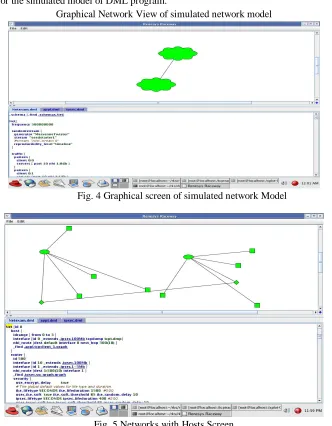
Theresults are analysed for the simulated model of DML program.
[image:3.612.142.474.302.728.2]Graphical Network View of simulated network model
Fig. 4 Graphical screen of simulated network Model
301
[image:4.612.146.465.71.259.2]©IJRASET: All Rights are Reserved
Fig. 3 Timeline Graph Screen
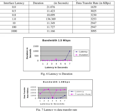
[image:4.612.113.505.317.697.2]Experiment-1: Influence of Router Bandwidth and Data Transfer Rate for the Host Bandwidth-100 Mbps, IKE Life duration -1000 s, IPSec Lifetime- 400 s, IPSec Timer interval-2s, IKE Timer interval- 2 s, the values are interpreted from running a model.
Table 2 Router Bandwidth: 1.5 Mbps
Interface Latency Duration (in Seconds) Data Transfer Rate (in KBps)
0.0 21.076 1639
0.5 11.423 3025
0.8 10.699 3230
1.0 136.369 3253
10 11.349 2947
100 11.727 2947
1000 11.166 3095
B a nd w id th 1 .5 M b ps
0 500 1 000 1 500
1 2 3 4 5 6 7
L aten cy in S ec ond s
D
u
ra
ti
o
n
i
n
S
e
c
o
n
d
s
La te ncy D uration
Fig. 6 Latency vs Duration
B a n d w id th 1 .5 M b p s
0 1 0 0 0 2 0 0 0 3 0 0 0 4 0 0 0
1 2 3 4 5 6 7
L a t e n c y i n S e c o n d s
D
a
ta
T
ra
n
s
fe
r
R
a
te
K
B
/S
e
c
L a t e n c y T r a n s f e r R a t e
Fig. 7 Latency vs data transfer rate
Inference: With increase in Interface latency data transfer rate increases and exceptional behaviour was noted when the Interface
International Journal for Research in Applied Science & Engineering Technology (IJRASET)
ISSN: 2321-9653; IC Value: 45.98; SJ Impact Factor: 6.887 Volume 6 Issue VII, July 2018- Available at www.ijraset.com
302
[image:5.612.101.509.84.193.2]©IJRASET: All Rights are Reserved
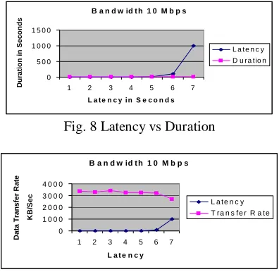
Table 3 Router Bandwidth: 10 Mbps
Interface Latency Duration (in Seconds) Data Transfer Rate (in KBps)
0.0 10.18 3395
0.5 10.5 3291
0.8 10.177 3396
1.0 10.5877 3264
10 10.696 3234
100 10.738 3218
1000 12.788 2702
Inference: As the Interface latency increases the data transfer rate decreases.
B a n d w id t h 1 0 M b p s
0 5 0 0 1 0 0 0 1 5 0 0
1 2 3 4 5 6 7
L a t e n c y i n S e c o n d s
D u ra ti o n i n S e c o n d s
[image:5.612.116.499.122.787.2]L a t e n c y D u r a t io n
Fig. 8 Latency vs Duration
B a n d w id t h 1 0 M b p s
0 1 0 0 0 2 0 0 0 3 0 0 0 4 0 0 0
1 2 3 4 5 6 7
L a t e n c y
D a ta T ra n s fe r R a te K B /S e c
L a te n c y T ra n s fe r R a te
[image:5.612.207.405.217.410.2]Fig. 9 Latency vs Data transfer rate
Table 4 Impact on Bandwidth
Bandwidth (in Mbps) Duration (in Seconds) Data Transfer Rate (in KBps)
1.5 10.81 3214
10 30.5 2448
100 23.5 2444
Im p a c t o n B a n d w id t h
0 5 0 1 0 0 1 5 0
1 2 3
B a n d w id th in M b p s
D u ra ti o n i n S e c o n d s
B a nd w d ith D ura tio n
Fig. 10 Bandwidth vs duration
I m p a c t o n B a n d w i d t h
0 1 0 0 0 2 0 0 0 3 0 0 0 4 0 0 0
1 2 3
B a n d w id t h i n M b p s
D a ta T ra n s fe r R a te in K B /Se c
B a n d w i d th T r a n s f e r R a te
[image:5.612.119.489.434.720.2]303
©IJRASET: All Rights are Reserved
Experiment-2 To measure the influence of Bit rate speed for various Bandwidths, the Bit rate was studied for 100, 1000, 10000 against 1.5 Mbps, 10 Mbps, 100 Mbps router with latency 0. IPSec timer interval 2s.
Router Bandwidth: 1.5 Mbps
Table 5 Bitrate Vs Data Transfer Rate: 1.5 Mbps
Interface Bit Rate Duration (in Seconds) Data Transfer Rate (in KBps)
100 11.561 2989
1000 11.132 3104
10000 11.179 3191
Inference: Data transfer rate Increases with Bitrate for 1.5 Mbps Router Bandwidth: 10 Mbps
Table 6 Bitrate Vs Data Transfer Rate: 10 Mbps
Interface Bit Rate Duration (in Seconds) Data Transfer Rate (in KBps)
100 10.757 3213
1000 10.901 3190
10000 10.887 3174
Inference: As the Bit rate increases the Data transfer rate decreases. Router Bandwidth: 100 Mbps
Table 7 Bitrate Vs Data Transfer Rate: 100 Mbps
Interface Bit Rate Duration (in Seconds) Data Transfer Rate (in KBps)
100 11.297 3059
1000 19.219 1898
10000 18.651 1853
Inference: As the Bit rate increases the Data transfer rate decreases. Experiment-3
This experiment is about study of the influence of IPSec timer interval to the Network.
Table 6.7 Influence of IPSec timer interval IPSec Timer
Interval in Seconds
Total Records
Used Total Bytes
Duration (in Seconds)
Data Transfer Rate (in KBps)
0.1 3456025 691204208 195.196 1.359
100 3481 695408 1.994 348
1000 371 73408 1.708 42
10000 61 11408 1.359 8
Inference: As the IPSec timer interval increases with the Data transfer rate increase.
III. CONCLUSION
International Journal for Research in Applied Science & Engineering Technology (IJRASET)
ISSN: 2321-9653; IC Value: 45.98; SJ Impact Factor: 6.887 Volume 6 Issue VII, July 2018- Available at www.ijraset.com
304
©IJRASET: All Rights are Reserved
impact on packet size, SA latency, rekey, does not give variations. These impacts have been studied using the default encryption, authentication used for the IPSec key management. This study can be extended to give efficient protection against packet at the time of communication by using various efficient algorithms, high speed processors.
REFERENCES
[1] Perlman R., Kaufman C., "Key Exchange in IPSec: Analysis of IKE", IEEE Internet Computing Journal special issue on Security Solutions, vol. 4, no. 6, pp. 50--56, Nov/Dec 2000.
[2] Soussi H., Hussain M., Afifi H., Seret D., “IKEv1 and IKEv2: A Quantitative Analyses”, WEC’05 Conference one security information, Istanbul, Turkey, 24 June 26, 2005.
[3] Okhee Kim, Doug Montgomery, “Behavior and Performance Characteristics of IPSec/IKE in Large Scale VPN’s”, IASTED International conference on communication, network, and information security, Dec 10 –12, 2003.
[4] Carlton R. Davis, “ IPSec: Securing VPNs”, Tata McGraw-Hill, New Delhi, 2001. [5] Douglas E. Comer, “Internetworking with TCP/IP”, Printice Hall of India, New Delhi, 2003. [6] John Mairs, “VPNs A Beginner’s guide”, Tata McGraw-Hill, New Delhi, 2002
[7] Richard Blum, “Network Performance Open Source Toolkit”, Wiley Publishers, India, 2003 [8] Richard E. Smith, “Internet Cryptography”, Addison Wesley, Second Indian Reprint , 2000. [9] William Stallings, “ Cryptography and Network Security”, Printice Hall of India, New Delhi, 2004. [10] Harkins D., Carrel D., “The Internet Key Exchange (IKE)”, RFC 2409, November 1998. [11] Hoffman P., “Algorithms for Internet Key Exchange version 1 (IKEv1) “, RFC 4109, May 2005. [12] Kent S., Atkinson R., "Security Architecture for the Internet Protocol", RFC 2401, November 1998. [13] Kent S., Seo K., “Security Architecture for the Internet Protocol “, RFC 4301, December 2005. [14] Kent S., Atkinson R., "IP Authentication Header", RFC 2402, November 1998.
[15] Kent S., “IP Authentication Header”, RFC 4302, December 2005.
[16] Kent S., “IP Encapsulating Security Payload (ESP)”, RFC 4303, December 2005.
[17] Maughan D., Schertler M., Schneider M., Turner J., “Internet Security Association and Key Management Protocol (ISAKMP)”, RFC 2408, November 1998. [18] McDonald D., Metz C., Phan B., “PF_KEY Key Management API, Version 2”, RFC 2367, July 1998.