580
©IJRASET: All Rights are ReservedEffect of Heat Transfer in a Circular Tube by using
Twisted Tape Inserts of different Material
Mr. Rahul S. Fartode1, Dr. Mangesh R. Dharme2, Mr. Shrikant S. Dandge3, Mr. Kishor R. Gawande4
1
PG Student, 2, 3, 4Assistant Professor, Department of Mechanical Engineering, Dr. Rajendra Gode Institute of technology and Research, Amravati, India
Abstract: An exploratory examination was conveyed for estimating tube-side warmth exchange coefficient, contact factor, warm exchange upgrade proficiency of Fluid (air) for turbulent stream in a round tube fitted with aluminum and copper curved tape as an embed. A steel tube of 19 mm internal diameter and 24 mm outer diameter and 1000 mm test length was used. An aluminum and copper twisted tape was inserted into the smooth tube. A uniform heat flux condition was created by wrapping coil wire heater around the test section and fiber glass over the wire. As the logic concern the 3 cases has been taken in consideration for comparative study between plain tube, aluminum twisted tape and copper twisted tape. The parameters like friction factor, Heat transfer coefficient enhancement factor, thermal performance factor etc. friction is directional to the surface area. As far results are concerned, in the percentage friction factor reduces by 5 to 15 % compared with aluminum twisted tape. Nu no. increases about 28 to 30% aluminum twisted tape and by 47 to 60% in copper twisted tape. Enhancement efficiency obtained by copper twisted tape experimentally is about 22 to 40% greater than plain tube.
Keywords: Reynolds number, twisted tape, Nusselt number, Conduction and convection heat transfer, Fluid flow, Heat transfer augmentation, Axial Convection, Radial Convection.
I. INTRODUCTION
A great deal of research effort has been devoted to developing apparatus and performing experiments to define the conditions under which an enhancement technique will improve heat transfer. Heat transfer enhancement technology has been widely applied to heat exchanger applications in refrigeration, automobile, process industries etc. The goal of enhanced heat transfer is to encourage or accommodate high heat fluxes. The need to increase the thermal performance of heat exchangers, thereby effecting energy, material and cost savings have led to development and use of many techniques termed as heat transfer augmentation. These techniques are also referred as Heat Transfer Enhancement or Intensification. Augmentation techniques increase convective heat transfer by reducing the thermal resistance in a heat exchanger. In order to improve the heat transfer efficiency and operation safety of heat transfer equipment, many techniques have been proposed , such as treated surfaces, rough surfaces, extended surfaces, swirl flow devices, shaped pipes, surface tension devices, technical aids, electrostatic fields, suction or injection. However, all of the above techniques will inevitably bring too much flow resistance, resulting in unnecessary power consumption. An effective method of heat transfer enhancement is required to not only improve the heat transfer greatly, but also minimize the flow resistance as much as possible. Flow resistance lead to increase in pressure drop. So, while designing a heat exchanger device using any of these techniques, analysis of heat transfer rate and pressure drop has to be done.
The major challenge in designing heat exchangers is to make the equipment compact and achieve a high heat transfer rate using minimum pumping power. Techniques for heat transfer augmentation are relevant to several engineering applications. In recent years, the high cost of energy and material has resulted in an increased effort aimed at producing more efficient heat exchange equipment. Furthermore, sometimes there is a need for miniaturization of heat exchangers in specific applications, such as space application, through an augmentation of heat transfer. Furthermore, as a heat exchanger becomes older, the resistance to heat transfer increases owing to fouling or scaling. These problems are more common for heat exchangers most of used in marine applications and in chemical industries. In some specific applications, such as heat exchangers dealing with fluids of low thermal conductivity (gases and oil) and desalination plants, there is a need to increase the heat transfer rate.
581
©IJRASET: All Rights are ReservedII. LITERATURE REVIEW
C. Thianponga [1] carried out an experimental investigation on heat transfer and pressure drop characteristics of turbulent flow in a heating tube equipped with perforated twisted tapes with parallel wings (PTT) for Reynolds number between 5500 and 20500. The design of PTT involves the following concepts: (1) wings induce an extra turbulence near tube wall and thus efficiently disrupt a thermal boundary layer (2) holes existing along a core tube, diminish pressure loss within the tube. The parameters investigated were the hole diameter ratio (d/W = 0.11, 0.33 and 0.55) and wing depth ratio (w/W = 0.11, 0.22 and 0.33). A typical twisted tape was also tested for an assessment. Compared to the plain tube, the tubes with PTT and TT yielded heat transfer enhancement up to 208% and 190%, respectively. The evaluation of overall performance under the same pumping power reveal that the PTT with d/W = 0.11 and w/W = 0.33, gave the maximum thermal performance factor of 1.32, at Reynolds number of 5500. Empirical correlations of the heat transfer, friction factor and thermal performance for tubes with PTTs were also developed. In addition, the swirling/axial flow patterns of tube with PTT were visualized using dye injection technique.
P.Eiamsa-ard et al [2] Investigated Effects of the regularly-spaced twisted tape (RS-TT) on the heat transfer, friction factor and thermal performance factor behavior sin a heat exchanger are reported along with those of a full length twisted tape. The full length(or typical) twisted tapes with two different twist ratios(y¼P/W¼6.0 and8.0),and the regularly-spaced twisted tape(RS-TT) with two different twist ratios(y¼6.0 and8.0)and three free space ratios(s¼S/P¼1.0,2.0,and3.0) were employed for comparative study .The article al so presents the application of a mathematical model for numerical simulation of the swirling flow in a tube induced by regularly-spaced twisted tape(RS-TT) insertion. The numerical simulation was performed in order to gain an understanding of physical behavior of the fluid flow (decaying swirling flow field), fluid temperature and local Nusselt number characteristics of a tube fitted with RS-TT in the turbulent flow regime. The Nervier–Stokes equation in common with the energy equation was solved using the SIMPLE technique with the RNG k–ε turbulence model. The experimental results show that heat
transfer rate and friction increased with decreasing twist ratio and space ratio. At similar conditions, full length twisted tapes (s¼0) offered higher heat transfer rate, friction factor and thermal performance factor than RS-TT ones (s¼1.0, 2.0and3.0) as they induced more consistent swirling flows and thus turbulence. This reveals that it is possible to gain promising tradeoff between enhanced heat transfer and increased friction by selecting the twisted tape with proper geometries.
Sh. Ghadirijafarbeigloo et al [3] studied on 3-D numerical simulation of heat transfer and turbulent flow in a receiver tube of solar parabolic trough concentrator with louvered twisted-tape inserts. Literature shows that absorber tubes with various tape inserts are used and recommended to produce high convection coefficient. Typical twisted-tape (TT) enhances heat exchange between tube surface and working fluid by generating turbulent swirling flow. In this study, enhancement of convection coefficient in the receiver tube of a solar parabolic trough concentrator that the absorber tube is equipped with a new perforated louvered twisted tape (LTT) is studied numerically. For numerical simulations three different twist ratios (TR), TR=y/W= 2.67, 4, 5.33 (y is the length required for one twist and W is the width of the tape) are used in an experimental laboratory trough collector. Flow is assumed turbulent due to louvered perforated surface and rotational shape of the tape. For thermal boundary condition, non-uniform wall solar heat flux is determined by Sol trace code on the outer surface of the absorber tube. Heat transfer rate and pressure drop are determined for fully developed condition for several Reynolds numbers based on the tube diameter and flow mean velocity. Results show that the heat transfer coefficient and pressure drop increase significantly in comparison with a typical plain twisted-tape in the tube and a plain tube.
III. EXPERIMENTALSETUP
The apparatus consists of a centrifugal blower unit fitted with a circular tube, which is connected to the test tube located in horizontal orientation. Flexi glass heater encloses the test section to a whole length of 1m. Input to heater is given through rheostat. Four thermo couples T1, T2, T3 and T4 at an equal distance of 15 cm from the origin of the heating zone are embedded on the walls
of the tube and one thermocouple is placed in the air stream at the exit (T5) of the test section to measure the temperature of flowing
582
©IJRASET: All Rights are ReservedFig. 3.1 Block diagram of required set up
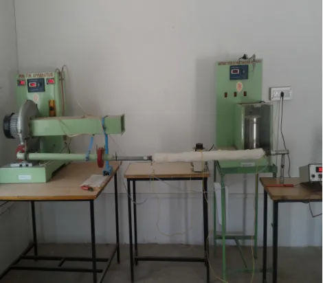
Fig.3.2: Experimental set up
A. Procedure
Air was made to flow though the test tube by means of blower motor. A heat input of 90 W was given to the Flexi Heater Coil wound on the test tube by adjusting the rheostat. The test tube was insulated in order to avoid the loss of heat energy to the surrounding. Thermocouples T1 toT4 were fixed on the test surface and thermocouples T5 were fixed near the exit of tube. The
[image:3.612.189.424.355.561.2]583
©IJRASET: All Rights are ReservedIV. EXPERIMENTALRESULTS
Table: Experimental Results for mass flow rate: 0.0065 kg/sec Parameters Plain Tube Twisted tape with
Aluminum
Twisted tape with Copper
Ti 30.5 31.2 32.4
T0 62 68 74.4
∆h 183.35 225.88 274.45
Re 25777.10 25747.431 25755.89
Nu 58.59 78.21 110.36
h 74.62 106.634 141.788
ff 0.0082 0.0207 0.0184
∆p 98.1 251.25 214.4
∆Pf - 2.5 2
ɳ% - 128.87 182.50
Tpf - 1.24705 1.7223
Comparative data tabulation makes easy to see the numerical values for each case in one line statement, definitely the values of parameters like temperatures, heat transfer coefficient, Re, Nusselt No. Pressure drop, etc. are very easy to understand and make a comparative decision, and opinion about tape or particular case. Above table is for air mass flow rate = 0.0065 kg/sec
V. CONCLUSION
1) The measurements are in good agreement with each other. The maximum error between the averaged experimental heat transfer enhancements with numerically predicted enhancement is 25%.
2) Nu no increases about 28 to 30 % in aluminum twisted tape, and by 47 to 60 % in copper twisted tape. Variations in experimental values are because of manufacturing and measuring errors.
3) Enhancement efficiency obtains by copper twisted tape experimentally about 22 to 40 % greater than plain tube, just due to resistance addition in the form of twisted tape.
4) Heat transfer enhancement in the form of augmented Nusselt number and heat transfer coefficient ratios h/h0 was observed.
Nu/Nu0 values decreased with increasing Reynolds number for both twisted tape. Nu/Nu0 values varied from about 1.2 to about
1.5 for the twisted tape in the Reynolds number range studied from 25000 to 95000. The corresponding values for the aluminum twisted tape was found in the range of 0.80 to 0.87 suggesting lower levels of heat transfer augmentation for the inline array case. The h/h0 values followed similar trend as the values Nu/Nu0.
5) The thermal performance factors were plotted for both the twisted tapes. The thermal performance values decreased with increasing Reynolds number values. Again the thermal performance factor values for the copper twisted tape were more than corresponding practical values for aluminum twisted tape in the Reynolds number range studied.
6) As the friction factor goes on decreasing as Re no increases. Experimentally for highest values of Re no it shows less deviation. 7) The heat transfer co-efficient and Nusselt number characteristics of copper twisted tape were enhanced rapidly
comparable of aluminum twisted tape.
8) The enhancement heat transfer twisted tape was achieved by due to the swirl flow action obtained from circular tube of copper twisted tape inserts.
VI. ACKNOWLEDGMENT
584
©IJRASET: All Rights are ReservedREFRENCES
[1] Thianponga, . Eiamsa-arda, Promvongea, S. Eiamsa-ardb, Effect of perforated twisted-tapes with parallel wings on heat transfer enhancement in a heat exchanger tube, 2nd International Conference on Advances in Energy Engineering (ICAEE2011)
[2] .P.Eiamsa-ard a, N.Piriyarungroj b, C.Thianpong b, S.Eiamsa-ard, A case study on thermal performance assessment of a heat exchanger tube equipped with regularly-spaced twisted tapes as swirl generators, Case Studies in Thermal Engineering 3(2014)86–102
[3] .Sh. Ghadirijafarbeiglooa, A. H. Zamzamianb, M. Yaghoubic, 3-D numerical simulation of heat transfer and turbulent flow in a receiver tube of solar parabolic trough concentrator with louvered twisted-tape inserts, Energy Procedia 49 ( 2014 ) 373 – 380
[4] S.A. Isaev, N.V. Kornev, A.I. Leontiev, E. Hassel, Influence of the Reynolds number and the spherical dimple depth on turbulent heat transfer and hydraulic loss in a narrow channel, International Journal of Heat and Mass Transfer, 2010, 53, pp.178-197.
[5] M.J.Patel1, K.S.Parmar, Umang R. Soni, Enhance the Performance of Heat Exchanger with Twisted Tape Insert: A Review, International Journal on Recent and Innovation Trends in Computing and Communication ISSN: 2321-8169 Volume: 2 Issue: 2
[6] P. Ferroni , R.E. Block , N.E. Todreas, A.E. Bergles, Experimental evaluation of pressure drop in round tubes provided with physically separated, multiple, short-length twisted tapes, Experimental Thermal and Fluid Science 35 (2011) 1357–1369.
[7] K. Wongcharee, S. Eiamsa-ard, Friction and heat transfer characteristics of laminar swirl flow through the round tubes inserted with alternate clockwise and counter-clockwise twisted-tapes, International Communications in Heat and Mass Transfer 38 (2011) 348–352.