Design and Analysis of Pipe Rack System using
STAAD PRO V8i Software
J. K. Sumanth1, Dr. C. Sashidhar2 1
M.Tech (Computer Aided Structural Engineering)Student, Deparment of Civil Engineering, JNTUA College of Engineering Anantapuramu, Andhra Pradesh, India-515002.
2
Professor of Civil Engineering, Department of Civil Engineering ,JNTUA College of Engineering, Anantapuramu, Andhra Pradesh, India-515002.
Abstract: In Industrial Plants like Oil & Gas, Petrochemicals, Refinery etc. Piperacks are most common structures which carries major Pipes with different diameters from one Equipment to another Equipment or from one unit to another unit. Pipe racks are main artery of the Oil & Gas Plants and hence detail planning and study are essential for any industrial projects. As the majority of material involves, there will be cost impact on the project and hence optimization is required. The Pipe racks have to be designed for majority of the loads like primary essential loads and pipe loads .The Analysis of the Pipe rack with suitable loads and with suitable configuration is carried out by using different Software like STAAD Pro, ANSYS, SAP etc. The Members of the Pipe racks has been designed by using Indian Standard, American Standard or British Standard codes as per requirement and location of the project.The Members of the Pipe racks has to be suitable verified for Strength, Vertical and Horizontal Deflection. The overall drift limit of the Pipe racks has to be maintained within the desired limit. A Piperack for the ongoing International project has been Analysed and Design of Super Structure has been carried out by using STAAD Pro software. Keywords: Pipe rack, Pipe sustained loads, Pipe Operating loads, Pipe test loads, Pipe Frictional forces, Pipe Anchor forces, Grids, cross beams, cable trays bracings moment connections, shear connections and Staad Pro V8i
I. INTRODUCTION
A. General
Pipe rack is concrete or steel structure which carries multiple pipes carrying liquid or gas in different tiers and also carries Electrical/Instrument/Telecom Cable trays and supports Auxiliary Equipment like Air Cooler, Pressure sustaining valves etc with service platforms and walkways.
Pipe racks carry large diameter to small bore lines with liquid or gas from one Equipment to another Equipment or from one unit to another unit. These are necessary for carrying large number of Process lines, Utility lines, Flare lines etc. Pipe racks are useful to carry Electrical, Instrumentation and Telecom Cable trays from one Equipment to Equipment and from one unit to another unit. Pipe racks are also useful for supporting Auxiliary Equipment like Air Coolers, Pressure release valves etc.
B. Objective
The main objectives of the thesis have been presented as follows.
1) Analyze and Design of steel pipe rack members using manual analysis as per codes specifications ASCE 07 and PIP(2007)STC
PIP 01015.
2) Model and analyze the steel pipe rack using STAAD Pro V8I.
3) Comparison of Manual Method of pipe rack with STAAD Pro V8I.
II. GENERAL ARRANGEMENT VIEWS
Figure 2.1 PIPE RACK MODEL IN 3D RENDERED VIEW
Figure 2.2 view of length of pipe rack and second bay
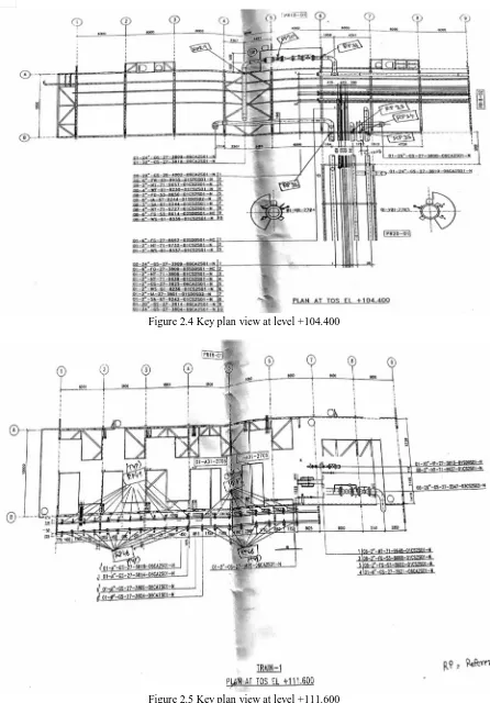
[image:2.612.87.532.480.712.2]Figure 2.4 Key plan view at level +104.400
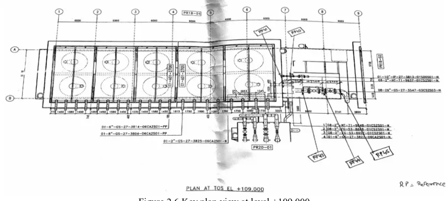
Figure 2.6 Key plan view at level +109.000
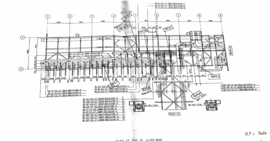
There are 8 Grids along the longitudinal direction (Grid-1,Grid-2, Grid-3 Grid-4 Grid-5 Grid-6 Grid-7 Grid-8)in which each grid is separated with a length of 6 meters.So overall length of the pipe rack is 42 meters.
There are two bays along the lateral direction ( one bay from A to B, and also a carriage way (from B to Grid-B1).From Grid-A to Grid-B distance between them is 10 meters. And from Grid-B to Grid-B1) the distance is 4 meters.
The analysing and assembling of beams, columns ,bracings(longitudinal, intermediate ,horizontal, plan) has been carried out and the pictures of assembling in STAAD is provided above.
As per the code specifications,
1) The length of each module of the pipe rack should be between 30-42m.So it is taken as 42m pipe rack length.
2) As there are two bays and it is more than one bay in transverse direction transverse column bracing is provided at the first bay
and at the bottom tier to top of the base plate.
3) A central longitudinal Tie beam has been provided at the centre as the width of the pipe rack is more than 5m.
4) Plan bracing and vertical bracing are provided as per the requirement in design and also to give clearance for the pipe routing
5) Cable tray supports are provided at 3m as it is maximum spacing.
6) The orientation of the columns is designed and placed as per the maximum moment of inertia.
7) As the width of the pipe rack is more than 4m in both bays. So both the bays are free to access for the human movement below
the bottom tiers.
8) The largest pipe diameter 30’’ is passing through Tier-1 Grid-8,the universal beam UB610X305X149 is used to withstand the
load.
9) Moment and shear connections are provided as per the design of the column and beam.
10) Vertical bracings are provided between Grid-5 and Grid-6 as the 18”and 24” diameter pipes and cable trays are passing through
these grids.
III. DESIGN METHODOLOGY
The design of the pipe rack PR18-01 is done on the basis of the standard load data given from the mechanical and piping department. The design is followed as per the specifications from the ASCE 07 and PIP(2007)STC PIP 01015.How ever the design may also depends upon the
1) Clients financial status and estimation,
2) The pipe rack local environment conditions,
3) Clients specifications, civil design basis.
4) Mechanical load General arrangement drawings.
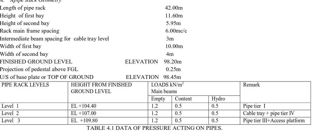
A. Apipe Rack Geometry
Length of pipe rack 42.00m Height of first bay 11.60m Height of second bay 5.95m Rack main frame spacing 6.00mc/c Intermediate beam spacing for cable tray level 3m Width of first bay 10.00m Width of second bay 4m FINISHED GROUND LEVEL ELEVATION 98.20m Projection of pedestal above FGL 0.25m U/S of base plate or TOP OF GROUND ELEVATION 98.45m
PIPE RACK LEVELS HEIGHT FROM FINISHED
GROUND LEVEL
LOADS kN/m2
Main beams
Remark
Empty Content Hydro
Level 1 EL +104.40 1.2 0.5 0.5 Pipe tier I
Level 2 EL +107.00 1.2 0.5 0.5 Cable tray + pipe tier IV
[image:5.612.41.576.83.308.2]Level 3 EL +109.80 1.2 0.5 0.5 Pipe tier III+Access platform
TABLE 4.1 DATA OF PRESSURE ACTING ON PIPES.
B. Design Loads Considered And Code Specifications For These Loads:-
1) Dead Load – DL: Superstructure weight consisting of self-weight of the structural steel members, handrails & grating weight
shall be considered as dead load. The grating self weight shall be considered as 0.5 kN/m2.Additional load of 12% of the
self-weight of structure shall be considered towards connection plates.
2) Live Load – LL: Live loads on the platforms, walkways and staircase are to be considered based on the usage and from design basis.
3) Fire Proofing Load – FP: The weight of fire proofing material applied to protect the structure against firehazards shall be
taken into account. Fireproofing weights shall be determined based on 34mm thick Fendolite - MII (Unit weight = 7 kN/m3)
applied in the shapeof the steel profile for sizes more than 200mm (in either dimension). For steelprofile of sizes 200mm or less solid fill shall be considered. Fireproofing shall be provided based on fire hazard assessments. This load shall be included in DL case.
4) Pipe Empty Load – PE: The Blanket load of 1.1 Kn/m2 for pipes less than 12 inch and actual empty weight for pipes greater than or equal to 12inch as given by piping discipline.
5) Pipe Operation Load – PO: The Blanket load of 0.6Kn/m2 for pipes less than 12 inch and actual content weight for pipes greater than or equal to 12inch as given by piping discipline.
6) Pipe Hydro Test Load – PT: PT is the weight of water in the pipe during the hydro-test. For hydro-test it is assumed that the two largest pipe sizes per tier on the rack are tested at the same time. All other lines are considered empty. For pipes less than
12 inch diameter, a uniformly distributed load of 0.6 kN/m2may be considered when a more definitive value for the weight of
water in the pipes cannot be established. The loads from the weight of water in the lines of 12 inch diameter and above shall be applied as concentrated loads at the pipe locations as given on the piping layouts and load data.
7) Longitudinal Pipe Friction Forces (PFL): A longitudinal horizontal force due to pipe friction equal to 10% of the pipe operating weight (empty pipes + pipe contents) shall be applied on each pipe supporting beam of the pipe rack. For small bore lines (less than 12 inch dia)above loads shall be taken as uniformly distributed. The friction loads shall be considered to be acting at the respective pipe locations on the beam.
8) Transverse Pipe Friction Forces (PFT): A transverse horizontal force due to friction equal to 5% of the pipe operating weight (empty pipes + pipe contents) shall be applied on each pipe supporting beams of the pipe rack. For small bore lines (less than 12 inch dia) above loads shall be taken as uniformly distributed.
9) Pipe Anchor Forces - PAL & PAT: Longitudinal and transverse anchor/guide forces (PAL & PAT) shall be thegreater of:
a) Loads as specified by Piping Department based on stress analysis results.
b) Longitudinal anchor load (PAL) equal to 10% of the pipe operating (emptypipes + pipe contents) weight per tier and transverse
IV. WIND LOADS ON PIPE RACK
A. Wind on Pipe rack Frames
Wind loads on pipe rack frame members shall be calculated using a pressure coefficient (Ct) of 1.2 for circular sections less than 150 mm diameter, 0.8 for circular sections greater than or equal to 150 mm diameter and 2.0 for flat shapes and rolled structural shapes. The effect of increased width / depth of member size due to fireproofing shall be accounted for.
Normal wind forces shall be considered to act during the hydro-testing of the pipes.
B. Transverse Wind Loads (WT) on Cable Trays
Wind load on the cable trays at each tier shall be determined as follows: Fdesign = qh*Ct*D*Lt
Where,
qh = Design wind pressure at height h
Ct = 2 + B/(25*D) ≤ 4
B = Total width across cable trays D = depth of cable tray
Lt =the tributary length of cable trays
C. Thermal Loads On Structure - Tr / Tf
For determining the effect of temperature variations on the exposed pipe rack structure, the temperature variations are computed for summer season and winter season.
The temperature rise in summer TR and the Temperature fall in winter TF shall be calculated.
D. Cable Tray Load – CL
Electrical or Instrument cable load (blanket) shall be 1.00 kN/m2 per cable tray. Incase the actual loading by
Electrical/Instrumentation/Telecom department exceeds the above load, the actual load shall be considered. For vertical drop oftrays along the column locations, uniformly distributed load shall be considered vertically at the respective column locations, for analysis.
E. Snow Load
Snow load shall be ignored for analysis and design of racks.
V. RESULTS AND DISCUSSION
The pipe rack PR18-01 is an international pipe rack project in the Saudi Arabia country. This pipe rack is designed as per the provisions and specifications of the ASCE 7-05 and also PIP(2007)PIP STC01015 and modelled in the STAAD PRO V8i software .The ASCE guideline should be considered as a reference document and not a design guideline.
The STAAD PRO V8i software has analysed this pipe rack in its soft ware in the LRFD method (Load Resistant Factor Design) of AISC 360-10 CODE OF BRITISH PRACTICE.
Various loads have been considered and applied on the structure. The primary loads As per ASCE 7-05 are
1.Dead Load (DL). Live Load (LL).
Empty Weight of Equipment (EE). Operating Weight of Piping (EO). Test Weight of Equipment / Piping (ET). Temperature load TL(+) & TL(-) Thermal friction Load (TF). Thermal Anchor Load (TA). Wind load (WL)
10.Blanket load.
A. Pipe Rack Design
There are 1247 beams,16columns and 86 bracings.All these beams,columns,bracings have
satisfied the allowable and safety requirements of the standard design basis of AISC 360-10 CODE OF BRITISH PRACTICE and the provisions of the PIP(2007)PIP STC01015 piping department.
Various results obtained from the staad model has been provided below in the form of pictures.
B. Model Result For One Column
One of the column result have been given below from the STAAD.PRO CODE CHECKING - (AISC-360-10-LRFD).
Sway Deflection Check
Horizontal Vertical Horizontal Resultant Rotational
Node L/C X mm Y mm Z mm Mm rX rad rY rad rZ rad
388
301 COMBINATION
LOAD CASE 6 6.223 -0.372 0.252 6.239 0 0 0
417
301 COMBINATION
LOAD CASE 6 6.11 -0.47 0.316 6.136 0 0 0
451
301 COMBINATION
LOAD CASE 6 5.575 -0.505 0.375 5.61 0 0 0
486
301 COMBINATION
LOAD CASE 6 4.999 -0.407 0.41 5.032 0 0 0
Height of pipe rack = 5950mm
Allowable deflection = H/325=18.30769mm As per Indian code criteria Actual deflection = 6.223mm<18.30769mm
SO SAFE IN DEFLECTION.
1) Utility Ratio Check
2) Plan Bracings Check
4) Longitudinal Bracings Check
6) Longitudinal Beams Check
VI. DISCUSSION ON RESULTS
1) In this pipe rack model design parameters has been applied in staad model under two different sections namely, Strength Design
& Serviceability.
2) To control the lateral moments the fixed but support is provided i.e,fixed in one direction and pinned in another direction.
3) The STAAD PRO V8i software analyses in the LRFD method so the result can be checked as per the strength.
4) The strength can generally be checked based on the UTILITY RATIO,DEFLECTION
5) According to the column result provided in 6.3.1 the strength ratio is 0.256 which is less than 1 as per AISC 360-10 So the
strength check is safe for this structure.
6) Slenderness ratio allowable is 200.00 an our actual obtained slenderness ratio is 83.000 so safe in slenderness ratio
7) Design parameter KZ is 1.00 for columns. allowable as per code is 1.2.
8) For the deflection check:- Height of pipe rack = 5950mm Allowable deflection = H/325=18.30769mm As per Indian code
criteria Actual deflection = 6.223mm<18.30769mm.SO SAFE IN DEFLECTION.
9) All the utility ratios checked in 6.3.3 are less than the allowable ratios
10) Plan bracings, longitudinal beams, transverse bracings, longitudinal bracings checks provided as in 6.3.4.6.3.5,6.3.6,6.3.7 are all
less than the allowable ratios.
11) Central longitudinal Tie beam has been provided at the centre as the width of the pipe rack is more than 5m as per code
specifications.
12) Plan bracing and vertical bracing are provided as per the requirement in design and also to give clearance for the pipe routing.
13) The orientation of the columns is designed and placed as per the maximum moment of inertia.
14) As the width of the pipe rack is more than 4m in both bays. So both the bays are free to access for the human movement below
the bottom tiers.
15) So the design and analysis has been followed as per the codes AISC 360-10 and PIP(2007)PIP STC01015 piping department
and also as per the clent requirement. So based on the above results we can see that the structure is safe.
VII. CONCLUSIONS
1) The pipe rack steel structure PR 18-01 has been modelled and analysed using LRFD(load resistant factor design) method in
American code AISC 360-10 CODE in STAAD PRO V8i software.
2) The tonnage of the whole structure was 1365.068 TONNES.
3) The orientation of the columns as I shape and H shape depends on the Moment of inertia.This moment of inertia in which shape
it is more, then that shape is opted.
4) All the bracings are provided as per project requirements.
5) Plan bracings are provided so as to resist the lateral deflection.also to transfer wind force,longitudinal forces to braced bay. The
shape of the plan bracings in this project are Rhombus shaped, L shaped.
6) This plan bracing shapes mainly helps to reduce the size of the structure and also to reduce the overall cost.
7) As the wind load and moment is there in the lateral direction so,we opted for fixed but support. This support is fixed in one
direction(x) and pinned in one direction(z).
8) Shear connections are provided as vertical bracings to carry the shear force to the base plates.
9) Moment connections are provided on the plan bracing and transverse bays where the pipe with larger diameters are rested on
this beams.
10) Expansion loop is provided for every 6m so as to control thermal stresses.(temperature load rise,temperature load fall) as per
code specifications).
11) Deflection was found to be under control (Allowable deflection=H/325=18.30679m, Actual deflection=6.223m).
12) The load data for the foundation design is generated and is provided in the results (output).
13) Typical single column member has been added in the result.
14) The governing case for the load combination is DEAD LOAD+WIND LOAD+PIPE OPERATING LOAD.
REFERENCES
[1] “Code of standard practice for Steel buildings and bridges (AISC 303-10)” American institute of steel construction (AISC) (2010) [2] “Minimum design loads for buildings and other structures (ASCE 7-10).” American Society of Civil Engineers (ASCE). (2010)’’ [3] Process Industry Practice PIP (2007), PIP STC01015, Structural Design Criteria,
[5] Nitesh J Singh et.al, “optimised design and analysis of steel pipe racks in oil and gas industries by international codes and standards.”IJRETVolume: 05 Issue: 10(Oct-2016)
[6] Anton stade aarønes et.al, “dynamic response of pipe rack steel structures to explosion loads” Master Thesis,chalmers university(2014)
[7] Preeti Rathore et.al,”Comparative Study and Cost Evaluation of combined pipe rack and Steel Pipe Rack”(IJSRD/Vol. 4/Issue 03/2016/296)(2016).
[8] Sabade Madhuri et.al,“Comparison Study of Effective Length Method (ELM) and Direct Analysis Method (DAM) for Piperack” IJSRSET Volume 3 issue 2(2017)
[9] Rupam saikia et.al,” seismic response of steel braced pipe racks and technological platforms in oil refineries” research gate.net/publication(2015) [10] Sebastián F. Vaquero et.al,“Precast concrete steel-braced, hybrid pipe rack structures" PCI journal(2013).
[11] Fabrizio Paolacci et.al, “seismic analysis and component design of refinery piping systems” III ECCOMAS Thematic Conference COMPDYN (2011) [12] Akbar Shahiditabar et.al, pipe and pipe rack interaction International Journal of Applied Science and Technology Vol. 3 No. 5; May 2013
[13] K. Naga Bharathi et.al,” The structural design and optimization of pre-assembled Piperack” IJOER Vol.5., Issue.2, 2017 March-April
[14] Mohammad Karimi et.al, “seismic evaluation of pipe rack supporting structures in a petrochemical complex in iran” International Journal of Advanced Structural Engineering, Vol. 3, No. 1,
[15] Sabade Madhuri, “Stability analysis of pipe racks in petro chemical Industries” International Journal of Advance Engineering and Research Development Volume 4, Issue 2, February -2017.
[16] STAAD.Pro V8i SS6 (2007). “Technical Reference Manual.” Bentley Systems, Inc., Yorba Linda, CA.
[17] Tekla International-Tekla Structures Construction software. American Institute of Steel Construction (AISC). (2005). “Specification for structural steel buildings (ANSI/AISC 360-05).” American Institute of Steel Construction, Inc. Chicago.
[18] American Institute of Steel Construction (AISC). (2010) “Specification for structural steel buildings (ANSI/AISC 360-10).” American Institute of Steel Construction, Inc. Chicago.
[19] American Society of Civil Engineers (ASCE). (2006) “Minimum Design Loads For Buildings and Other Structures (ASCE 7-05).” American Society of Civil Engineers, Reston, VA.