Abstract—This paper reports the relationship between residual stress distribution and key friction stir welding parameters, transverse and rotational speeds, on 6056-T4 aeronautical aluminium alloy. Standard electric strain gauge based destructive technique was used to measure residual stresses at the top of the weld in the longitudinal direction. Residual stresses across the weld had the “M” distribution with asymmetry across the advancing and retreating sides. Location of retreating side tensile residual stress maximum was the weakest zone and microhardness minimum across the weld. Tensile longitudinal residual stress minimum and maximum at the retreating side of the weld reduced with increased translational speed and advance per revolution.
Index Terms— Advance per revolution, electric strain gauge destructive technique, friction stir welding, residual stress, triflat FSW tool
I. INTRODUCTION
riction stir welding (FSW) is the fastest evolving joining technology and was developed by TWI in 1991. It uses a non-consumable rotating tool, which comprises a shoulder and a profiled probe protruding from it, plunged into the abutting sheets to stir and forge the material as it moves along the joint line, while the trailing side of shoulder consolidates the joint [1]. Friction stir welding (FSW), being a process in solid state, induces frictional heat between the materials and the tool; hence no more than 85% of the melting temperature of the material is reached. This is responsible for the advantages of repeatability, low distortion and absence of solidification cracking in the weld and weldability of all aluminium alloys.
Manuscript received December 30, 2012. This work was supported by the African Materials Science and Engineering Network (AMSEN, A Carnegie-RISE network) and the DST/NRF Centre for Excellence in Strong Materials, University of Witwatersrand, Johannesburg.
O.J. Dada is with the Federal University of Technology, Akure (FUTA), Ondo State, Nigeria, registered at University of the Witwatersrand, Johannesburg, where the research was carried out. (e-mail:
Oluwaseun.Dada@students.wits.ac.za, ojdada@futa.edu.ng, oluwaseundd@yahoo.com).
C. Polese is an Associate Professor, Mechanical, Industrial and Aerospace Engineering, University of the Witwatersrand, Johannesburg. (e-mail: Claudia.Polese@wits.ac.za).
L.A. Cornish is a Professor and the Director, African Materials Science and Engineering Network (AMSEN, A Carnegie-RISE network) and the DST/NRF Centre for Excellence in Strong Materials), School of Chemical and Metallurgical Engineering, University of the Witwatersrand, Johannesburg. (e-mail: Lesley.Cornish@wits.ac.za).
FSW is the leading prospective technology for implementing integral fuselage structure to reduce cost, man-hour, weight, energy consumption and avoid wide spread fatigue damage which is associated with the traditional fastening method of riveting [2]. Despite these undeniable advantages, residual stresses which are thermally induced negatively influence the mechanical properties and stress corrosion behaviour of friction stir welds. This study presents the relationship between rotational and translational speeds, which are key process parameters, on Triflat tool friction stir welded 6056-T4 aeronautical aluminium alloy. The AA6056-T4 is similar to AA6013-T3. It has similar mechanical properties to AA2024 and it was developed to replace it. AA6056-T4 has improved weldability with good strength and corrosion resistance and it is formed by the addition of Si-Mg-Zn-Cu-Mn [3].
II.EXPERIMENTAL PROCEDURE
Aeronautical alloy AA6056-T4 was welded using the Triflat tool (Figure 1) at 300-500mm/min translational speed and 1600-2000rpm rotational speed of the tool (Table 1) on a converted CNC milling machine at University of the Witwatersrand, Johannesburg. The dwell time was 8 secs and depth of penetration below the workpiece surface is 0.1mm. The 300mm × 250mm × 1.6mm plates were welded parallel to the rolling direction. The chemical composition of the alloy is given in Table 3. Surface preparation of sectioned FSW joint was done using Struer’s Labopol-21 and Weck’s reagent was used to reveal the microstructure. Light microscopy was done on the Leica DFC 490C light microscope using polarized light with a sensitive tint. Residual stress measurements were done using the electric strain gauge based destructive method, which is a proven measurement technique [4]. The welded plates were instrumented with Kyowa KFG-2-120-C1-11 and Kyowa KFG-5-120–C1-11 strain gauges at different positions. Strain measurements were taken in the longitudinal direction across the welds at the retreating and advancing sides. The strain measurements were converted into residual stresses by using Hooke’s law.
Relationship between Residual Stresses and
Welding Rates in Friction Stir Welded
AA6056-T4
Oluwaseun John Dada, Member, IAENG, Claudia Polese, and Lesley A. Cornish
Figure 1. Scroll shoulder Triflat (TFT) FSW tool having pin with three equidistant flats (tool).
Table 1. Welding rates of FSW AA6056-T4.
Sample A B C D E
Rotational Speed 2000 2000 2000 1600 1250
Translational Speed
300 400 500 300 300
Table 2. Chemical composition of AA6056-T4 (wt%) [5].
Si Fe Cu Mn Mg Zn Al
0.87 0.07 0.67 0.62 0.71 0.18 Balance
III. RESULTSANDDISCUSSION A. Microstructure across the joint
The microstructure across the joint is given in Figure 2. All FSW microstructural zones were identified namely: (a) Weld nugget: which is the zone of intense stirring and severe plastic deformation, resulting in high thermal evolution and dynamic recrystallization, that brings about the formation of fine equiaxed grains arranged in an onion ring structure. The flow arm zone is above the onion ring, contains finer grains due to more intense deformation from the tool shoulder, (b) Thermomechanically affected zone (TMAZ): which directly adjoins the weld nugget on both sides, where the microstructure have been influenced by both thermal evolution and reaction from tool rotation. On the advancing side (on the right), there was a clear weld nugget/TMAZ interface, but on the retreating side there was no interface. This is due to higher shear rate, higher heat transient generation on the advancing side than the retreating side. (c) Heat affected zone (HAZ): where the state of precipitation has changed and grain have enlarged due to transient heat from the weld nugget [6].
A – Weld nugget B – Flow arm zone C – Weld root
D – Thermomechanically affected zone (TMAZ) E – Advancing side heat affected zone
F – Retreating size heat affected zone G – Unaffected base material
Figure 2.Light microscope image of TFT-1 FSW AA6056-T4 showing the all the microstructural zones.
B. Microhardness distribution
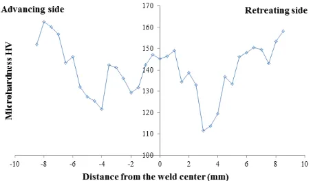
[image:2.612.314.540.425.557.2]Microhardness values across the join exhibited the “W” distribution, typical of most FSW 6XXX alloys [1]. The hardnesses in the weld nugget were slightly irregular and higher than at the TMAZ next to the weld nugget where there were microhardness minima. The microhardness minima on the retreating sides of all the samples were lower than those of the advancing sides. The retreating side hardness minima, which doubled as the static fracture location in the welds, were the weakest part of the weld [6].
Figure 3. Microhardness of Triflat tool FS welded AA6056-T4.
C. Residual stress distribution across the welds
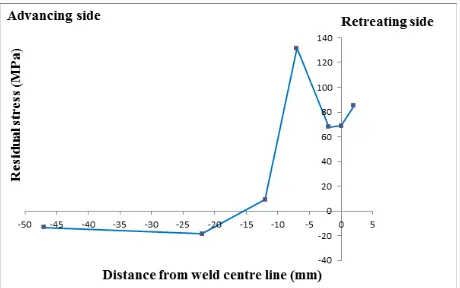
next to the weld nugget. The retreating side maximum tensile residual stresses were lower than those of the advancing side in the welds due to a higher shearing rate and heat generation. However, the retreating side TMAZ’s were found to be the weakest zones in the welds as indicated by micro-hardness results and static fractures. Maximum compressive stresses were at 20mm away from the weld centre line.
The average residual stress in the weld nugget was 50.07 ± 3.63 MPa, which was 16.92% of the yield strength of the base material. The average maximum tensile residual stress on the retreating side was 116.15 ± 9.76 MPa, which was about 39.24% of the yield strength of the base material. Maximum compressive stresses were low, with an average of 14.70 ± 1.98 MPa, which was 4.97% of the yield strength of the base material. The average maximum tensile residual stress on the advancing side were high, with an average of 123.38 ± 8.12 MPa, which was about 41.68% of the yield strength of the base material. Compressive residual stresses on the advancing side were higher than those on the retreating side of the weld, due to higher transient heat and thermal constraint. The average maximum compressive stress was 20.86 ± 0.61 MPa, which was 7.05% of the yield strength of base material, which is fairly low and should have no adverse effects.
[image:3.612.313.543.61.205.2]Figure 4. Residual stress distribution across Specimen C.
Figure 5. Residual stress distribution across Specimen B.
Figure 6. Residual stress distribution across Specimen E.
D. Relationship between residual stresses and translational speed
[image:3.612.69.303.355.496.2] [image:3.612.314.544.431.563.2]The maximum tensile residual stresses, which were near the TMAZ/HAZ junction, reduced with increased welding speed, at constant rotational speed of 2000rpm. The minimum residual stresses which were in the weld nugget, reduced slightly, while maximum compressive residual stresses increased at increased welding speed, as shown in Figure 7.
At increased welding speed, less work was done on the joint per rotation of the FSW tool, hence, lesser mechanical constraint and lower heat that resulted in less residual stresses.
Figure 7. Relationship between overall residual stress data and welding speed at contant rotational speed of 2000rpm in TFT FSW AA6056-T4.
E. Relationship between residual stresses and rotational speed
[image:3.612.71.299.558.704.2]Figure 8. Relationship between overall residual stress data of the plates and rotational speed at contant welding speed of 300mm/min in TFT FSW AA6056-T4.
F. Relationship between residual stresses and advance per revolution
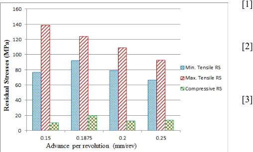
Maximum tensile residual stresses at the retreating side of the weld were found to generally decrease with increasing advance per revolution, as shown in Figure 9. The higher the advance per revolution, the less work was done on the weld per unit revolution of the tool. The residual stresses were inversely proportional to the advance per revolution. Increased advance per revolution is associated with lower temperature, because the tool spends less time in a specific region. The relationship between the minimum tensile residual stresses and compressive with advance per revoluion were the same as that of the maximum residual stresses, except at 0.1875mm/rev advance per revolution which was the highest.
Figure 9. Relationship between overall residual stress data and advance per revolution towards the retreating side of the TFT FSW AA6056-T4.
It was established that maximum tensile residual stresses were lower at the retreating side TMAZ/HAZ junction than at the advancing side of TFT FSW AA6056-T4. However, the microhardness profile, microstructure and the static fracture [6] showed that the TMAZ/HAZ junction on the retreating side was weaker than that on the advancing side. Hence, reduction in welding speed primarily to reduce the retreating side tensile residual stress maximum is required, for not only improving the tensile properties of the joints, but also for optimizing the cyclic mechanical behaviour and
welded integral frame structures in 1.6mm thick AA6056-T4.
IV. CONCLUSION
The residual stress measurements across Triflat tool friction stir welds of AA6056-T4 aeronautical alloy was successfully measured using the electric strain gauge technique and reported in this paper. Residual stress exhibited the “M” distribution, with asymmetry across the advancing and retreating sides of the weld. Reduction in longitudinal residual stress minima and maxima, which may be detrimental to the integrity of friction stir welded AA6056-T4 would generally require an increasing welding speeds and advance per revolution. Future work would include but not limited to the testing of similar alloys welded with broader range of friction stir welding parameters.
ACKNOWLEDGMENT
I acknowledge the support of Daniel Correia and Lumka Msibi of the School of Mechanical, Industrial and Aerospace Engineering, African Materials Science and Engineering Network (AMSEN, A Carnegie-RISE network) and the DST/NRF Centre for Excellence in Strong Materials, University of Witwatersrand, Johannesburg.
REFERENCES
[1] R. S. Mishra and M. W. Mahoney, Friction Stir Welding and Processing. ASM International, 2007, pp. 1–352.
[2] A. Lanciotti and C. Polese, “Impact of Direct Water Cooling on the Quality and Performance of Friction Stir Welded Joints in a AlMgSiCu Aluminium Alloy,” 2004.
[3] S. T. Amancio-Filho, S. Sheikhi, J. F. dos Santos, and C. Bolfarini, “Preliminary study on the microstructure and mechanical properties of dissimilar friction stir welds in aircraft aluminium alloys 2024-T351 and 6056-T4,” Journal of Materials Processing Technology, vol. 206, no. 1–3, pp. 132–142, Sep. 2008.
[4] G. Ivetic, a Lanciotti, and C. Polese, “Electric strain gauge measurement of residual stress in welded panels,” The Journal of Strain Analysis for Engineering Design, vol. 44, no. 1, pp. 117–126, Jan. 2009.
[image:4.612.70.324.410.563.2][6] O. J. Dada, “Characterisation of Innovative Friction Stir Welding for Aeronautical Structures: M.Sc Eng Dissertation Submitted to University of the Witwatersrand, Johannesburg,” 2012.
[7] K. Deplus, A. Simar, W. Van Haver, and B. De Meester, “Residual stresses in aluminium alloy friction stir welds,” The International Journal of Advanced Manufacturing Technology, vol. 56, no. 5–8, pp. 493–504, Feb. 2011.
[8] L. Commin, L. Barrallier, and J. Masse, “Residual stress evolution analysis in AZ31 friction stir welds using X-RAY and neutron diffraction,” JCPDS-International Centre for Diffraction Data, vol. 1097, no. 002, pp. 624–632, 2009.