Abstract—To achieve the high bio-imitability requirements, we propose a novel human jaw movement robot based on mechanical biomimetic principles. First, according to the biomechanical properties of mandibular muscles, such as unsymmetrical distribution, force with different direction and the joints in maxillary and mandible is non-coplanar, a robot that simulates the jaw movements is built based on the 6-PSS parallel mechanism. Then, its inverse kinematics solution equation and Jacobian matrix are driven. Finally, experiment study of jaw movement on the platform of virtual prototype shows that the parallel mechanism can meet the demands, such as reality of mandibular movement trajectory and rationality of occlusal force.
Index Terms—jaw movement robot, parallel mechanism, kinematics analysis, simulation
I. INTRODUCTION
uman mandible system mainly consists of lower jaw, muscle and temporal mandibular joint. Performing complex periodic opening and closing movement relative to the maxillary in three-dimensional space, lower jaw is alternately driven by several opening and closing muscles [1]. Jaw muscles mainly include the masseter, temporallis, and pterygiod muscle, which present symmetric distribution [2]. In the physiological activities of the human body, jaw system assumes the responsibility of several essential physiological functions, like chewing food, expressing language and controlling expressions.
The research of the jaw movement robot which can simulate human mandible movement and reproduce human mandible force began in the 1990 s [3]. In accordance with the application field of the jaw movement robots, they can be classified as follows: In dentistry, such as Alemzadeh etc [4] developed a dental test simulator based on Stewart platform, This work was supported in part by the China State Key Laboratory of Robotics.
Cong Ming is with the School of Mechanical Engineering, Dalian University of Technology, Doctor, Professor, research fields: mechanism and robotics, bionic robot and control, industrial robot technology and application, intelligent control, CO 116024 China (e-mail: congm@ dlut.edu.cn).
Du Jing is with the School of Mechanical Engineering, Dalian University of Technology, Master, research field: bionic robot, CO 116024 China (phone: 18698611837; e-mail: djbld@ qq.com).
Liu Tongzhan is with the School of Mechanical Engineering, Dalian University of Technology, Master, research field: bionic robot, CO 116024 China (e-mail: [email protected]).
Wen Haiying is with the School of Mechanical Engineering, Dalian University of Technology, PHD candidate, research field: bionic robot, CO 116024 China (e-mail: [email protected]).
Xu Weiliang is with the Department of Mechanical Engineering, the University of Auckland, Doctor, Professor, research fields: robot intelligent technology, humanoid robot, chew robot, intelligent electromechanical integration design, CO 1142 New Zealand (e-mail: [email protected]).
which can be used for experiment of dental component material. Callegari etc [5] propose a kind of 3-PUU parallel mechanism that can auxiliary dentist to perform dental disease pathology research in the mandible motion situation. The biological characteristics of human mandible system has not been considered in the two robots above, so they could not really reappear function and environment of the mandible movement; In food science, references [6]–[9] has made the unique contribution to the mastication robot. Among them, the mechanism, which the article [8] proposes, exists serious problems of the singular configuration so that it couldn’t achieve the required mandible movement and bite force during the process of food chewing; In biomechanics, there are Mark Ⅲ mastication mechanism [10], JSN chin simulator [11]-[12], and mandible motion simulator [13] etc, which are mainly used to study the movement characteristics of the mandible system. In addition, Takanobu etc [14] developed a rehabilitate robot aiming at mandible movement, and E. Flores etc [15] propose a language physical therapy robot for the research of perception and comprehension function in the process of talking face to face.
Synthetically considering the biological characteristics of the mandible muscles, including asymmetry distribution, different direction of the force, and non-coplanar junction of the mandible bones, this paper designs a new jaw movement robot based on the mechanical bionic principle. In accordance with the characteristics of the new jaw movement robot, this paper combines with the analytical method, the kinematics simulation and experiment test to analyze and verify the feasibility of the structure design, the reliability of the movement trajectory and the rationality of the bite force.
II. DESIGN OF JAW MOVEMENT ROBOT A. Design of the General Structure
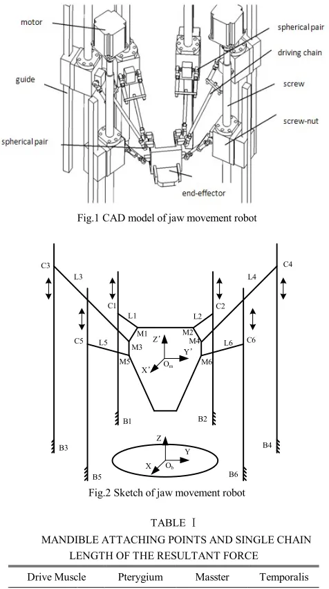
The CAD model and sketch of jaw movement robot, including the end-effector( mandible mechanism) and six branched chains of the kinematic pairs are shown in Fig. 1 and Fig 2. In the CAD model, the support and upper jaw of the structure are omitted to simplify the mandibular structure. The force from mechanism branched chains to mandible, whose point is located at the connection of jaw muscle, works in the direction of muscle action line. In the structure, spherical joint S and shifting pare P are used to simulate the muscle contact point and driving muscle, respectively. The position of the sliders is changed through motors to implement mandible space motion.
Design and Simulation Experiment Research of a
New Jaw Movement Robot
Cong Ming, Du Jing, Liu Tongzhan, Wen Haiying, Xu Weiliang
Fig.1 CAD model of jaw movement robot M1 M2 M3 M4 M5 M6 C1 C2 C5 C6 C3 B5 B3 B1 B6 B4 B2 X’ Y’ Z’ Z X Y L1 L6 L5 L4 L2 L3 C4 Om Ob
Fig.2 Sketch of jaw movement robot TABLE Ⅰ
MANDIBLE ATTACHING POINTS AND SINGLE CHAIN LENGTH OF THE RESULTANT FORCE
Drive Muscle Pterygium Masster Temporalis x 0 20.3 28.3 y -42.2 -45.2 43.3 Mandible
Attaching Points Mi
(mm) z 0 -45.4 5.8 x -96.1 60.3 -30.7 y 60.5 100.5 130.0 Maxilla
Attaching Points Ci
(mm) z 0.3 5.2 55.2 Chain
Length Li(mm)
127.0 121.0 183.9
B. Design of the Mandible Driving Muscle Structure The coordinates of the points connected the drivers and jaw bones coincide with the connection positions of the mandible driving muscles. J.H.Koolstra etc [16] has measured the parameters of those muscles, including position of connection points, length, and cross sectional area etc. Comprehensively considering the high bionic design and feasibility requirements of the mechanism, this paper deduces the action points, which connect each branched chain with upper and lower jaw mechanisms, and the length of each branched chain. Owing to the complete symmetry between both side muscles, the paper just shows the action
points position of the left muscles’ resultant forces in the mandible coordinate, as shown in TABLE Ⅰ.
III. INVERSE KINEMATICS
In order to develop the robotic mechanism, a frame Oxyzb (or static frame) and a frame Oxyzm (or mandible frame) are established based upon the human skull and mandible. The origin of the mandible frame which has a sagittal plane (x-z plane), a frontal plane (y-z plane), and a horizontal plane (x-y plane) is located at the symmetrical center of the mandibular molar. The position of the mandible frame relative to the static frame can be determined by homogenous transform bR
m as follows:
(1)
In which: c―cos,s―sin.
In which,
Tmz b my b mx b m b O O O
O , , is the origin of the Oxyzm with respect to Oxyzb, and
,,
are roll-pitch-yaw rotational angles about the static frame’s x, y and z axes, respectively. The position and posture of the mandible mechanism change from the two group decision variables above.The completed robot displays the following configuration for the initial position:
T
Tmz b my b mx b O O
O , , 0,0,100 ,
,,
0,0,0
On one hand, vector BiMi as shown in Fig. 3 can be found explicitly as follows:BiMi BiObObOmOmMi (2)
zi yi xi b m mz b my b mx b zi yi xi i i B B B R O O O B B B M
B (3)
Where the first term BiObis determined by the location
coordinates of Oyyzb on the static frame; the second term m
bO
O is determined by the initial position and posture of the mandible; and the third term OmMiis determined by the
location of Mi on the mandible.
On the other hand, vector BiMican also be expressed by: BiMi BiCiCiMi (4) Rearranging (4) gives rise to:
CiMi BiMiBiCi (5) Further squaring the norm of the above vector equation yields:
CiMi 2 BiMi 22BiMiBiCi BiCi 2 (6) In which CiMi Li
i1,2,,6
is the length of each bar, and BiMiis calculated by (3).Letting2 2 i i
iM r
The vector direction of BiCi is
Te 0,0,1 , so
BiMiBiCi BiMieqi (8) In which qi BiCi is the motional variation amount of the slider relative to the guide.
Letting ci BiMie, (8) can be re-arranged as: BiMiBiCiciqi (9) Putting (7) and (9) into (6) results in:
qi22ciqiri2Li20 (10) Eventually, the two inverse solutions for each motional variation amount of the slider are found explicitly:
2 2 2 i i i i
i c c r L
q (11)
Fig.3 Sketch of the single chain
IV. DERIVATION OF THE JACOBIAN MATRIX
The spherical joints, with the partial freedom, are used in the both ends of the branched chains so that the jaw movement parallel mechanism also has the partial freedom. However, the partial freedom has no impact on the motion performance of the mechanism. Meanwhile, there is no redundancy drive in the mechanism, so the linear relation between each branch chain pose’s input θ and mandible pose’s output X can be expressed as :
f
,X
(12) Jacobian matrix can be used to describe the relationship between the speed of each branch chain and the mandible platform (the end-effector). According to the (12):f
,X
(13) According to the Jacabian matrix established by the (13), project the velocity of hinge points Mi and Ci along each branch chain:
vOmMi
CiMi vieCiMi (14) In which ν and ω present the translational velocity vector and angular velocity vector, respectively; vi is the velocity ofthe slider;
Te 0,0,1 is the unit vector direction of the guide. (14) can be rewritten by the matrix form as follows:
m m m b m m b m m b m v M C M O R M C M C M O R M C M C M O R M C 6 6 6 6 6 2 2 2 2 2 1 1 1 1 1 6 2 1 6 6 2 2 1 1 0 0 0 0 0 0 v v v e M C e M C e M C
(15)
The matrix form of (15) is:
J
X
JX (16) In which,
Tm m
v
X ,
Tv v v1, 2,, 6
.
V. RESEARCH OF SIMULATION EXPERIMENT A. Establishment of Mandible Simulation Platform and Attitude Definition
First of all, according to the parameters of the mandible platform structure and the muscle insertion points, the paper sets up a virtual prototyping robot model in ADAMS, which can simulate the mandible movement. As shown in figure 4, the simulation of the mandible movement in ADAMS performs 5 periodic motions with interval of 1s and their motion attitude shows as follows: irregular open-closed movement, bite movement, left chew, conventional
open-closed movement, and right chew. The difference of the definition between irregular open-closed movement and conventional open-closed movement lies as follows: Irregular open-closed movement can be considered that the mandible performs certain movement in the direction of right and left during the opening and closing movement;
Conventional open-closed movement has no such right and left movement. Bite movement means that the mandible not only bites up and down, but also has the action of grind and tore. Left and right chewing movement can be deemed as the process of bite and grind with unilateral tooth.
(a) irregular open-closed movement (b) bite movement
(e) right chew
Fig.4 A frame of mandible simulation cartoon in different attitude
To analyze the trajectory of the mandible movement, the following reference points are used to describe mandible motion: IP(incisal point), LMP(left first molar point), RMP(right molar point), LCP(left condylar point), RCP(right condylar point). The position of the reference points in mandible coordinate is presented as in TABLE Ⅱ and Fig.5.
TABLE Ⅱ
POSITION OF REFERENCE POINTS IN MANDIBLE Reference points X(mm) Y(mm) Z(mm)
IP 80.0 0 -38.8
RMP 45.2 -12.2 2.0
LMP 45.2 12.2 2.0
RCP 5.0 -47.3 -5.0
LCP 5.0 47.3 -5.0
Fig.5 Position of jaw reference point
B. Simulation Experiment of Mandible Platform Movement
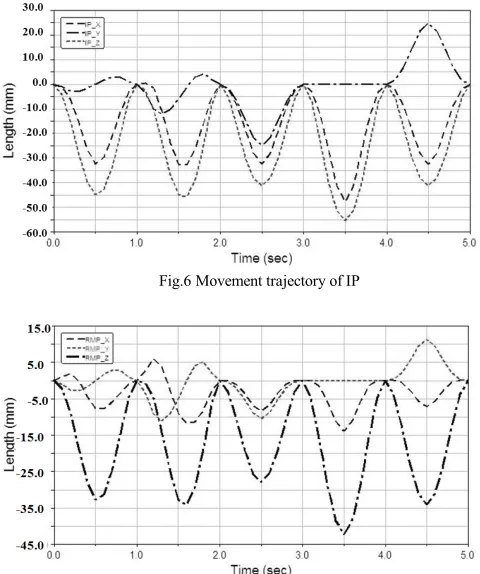
In the cases of five different movement posture defined, considering the symmetry of RCP and LCP as also RMP and LMP, the ADAMS Postprocessor analyzes the reference points IP, RMP, RCP in the X, Y, Z direction of trajectory, as shown in Fig. 6-8 below.
The displacement curves of the three reference points in figures show the relative displacement of the mandible platform from the initial position of the stationary state to the above five kinds of movement.
Through comparisons and analyses, it can be concluded that the relative displacement of IP point in direction Z reaches the largest amount--55.1 mm in 3.5s. At this time the mandible platform is in the stage of the conventional open-closed movement, moreover, the displacement in the direction X of the three reference points is almost zero, which is consistent to human mandible trajectory. In the normal human mandible movement process, the range of mandible upper and lower movement is remarkably large, as also as left
[image:4.595.305.545.216.503.2]and right movement, but the changes are small in the direction of front and back. At 4.5 s, IP point and RCP point in the direction Y have conspicuous mutation, mainly due to the chewing and tearing movement of the mandible platform’s right tooth. In the IP movement situation, for example, the maximum displacement in the direction of X, Y and Z are 47.1 mm, 25mm and 55.1mm, respectively, which is consistent with the movement of human incisal point. The fact shows that the jaw movement robot, considering the biomechanical characteristics of the mandible drive muscles and the feasibility of mechanism design, may truly represent human mandible trajectory.
Fig.6 Movement trajectory of IP
[image:4.595.309.547.537.669.2]Fig.7 Movement trajectory of RMP
Fig.8 Movement trajectory of RCP
mm, which is basically consistent with the movement range of the incisal center point when the opening angle of human mouth is 30 degrees. The result states that the jaw movement robot can meet the reliability requirement of the movement trajectory.
Fig.9 Movement trajectory of reference points
C. Mandible Drive System Analysis
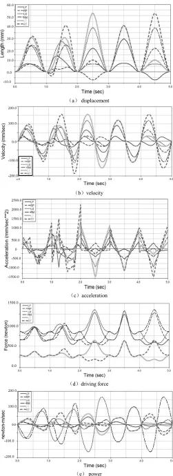
The jaw movement is controlled by the motion of the slider along the guide which is driven by the system consisting of motor and screw-nut , and the branched chains which simulate the closing muscle group drive the mandible platform to realize the human mandible movement trajectory. The posture change of the mandible platform depends on the sliders’ movement range. The figure 10 shows the characteristic curves of the slide movement along the guide in each branched chain.
Figure (a) shows the displacement of the slider, thereupon, it can be concluded that the masseter reaches the maximum displacement at different posture, which is consistent with the characteristics of the masseter in human mandible system. In 4-5 s, the right masseter performs chew movement, whose maximum of the displacement variation is 40 mm, and it can be confirmed that the food is ground manly by the function of masseter at this time. As shown in Fig.(b) and Fig.(c), the velocity and acceleration of the left and right masseters vary alternatively in 1-2 s and 4-5 s periods. The Pterygiumin has the minimal motional variation during the whole mandible movement process, in that the pterygium is near the axis of the temporomandibular joint in the human mandible system (it can be simply thought that the mandible rotates along the axis).So the pterygium plays an insignificant role in the process of mandible biting movement and hard food chewing. As Fig.(d) shows, with definite load, the changes and sizes of the mandible muscles’ driving force are consistent with the mandible posture at this time. The robot performs the mandible bite movement during 3-4 s, because the load forces and driving forces are in opposite directions, the driving force reaches the largest about 1893 N at the same time. Fig.(e) shows the one side chewing movement in 2-3 s and 4-5s. During the movement, the largest driving power of the temporails is about 144.2 W, which is consistent with the position of the load as well and provides the selection basis of the driving device.
In a word, the simulation experiment shows that this jaw
movement robot can truly represent the human mandible movement and the mechanics characteristics.
(a) displacement
(b)velocity
(c)acceleration
(d)driving force
(e) power
[image:5.595.69.270.123.271.2]D. Hardware Configuration and Prototype Model of Mandible Drive System
Under certain load, the jaw movement robot completes such movements as closing, biting and unilateral chewing, so the motors on the drive device should change rotation direction frequently and speed up instantaneously. Considering the gravity of the mandible platform and branched chains, in the process of power up and down, motor brake function should be added to realize the power-off protection, avoiding the sliding of the motors leading to the damage of the mechanism. Meanwhile, as the structure space of the mandible is small, the installing space of the motors should be considered seriously. In a word, in order to meet the motion requirements of the jaw movement robot, including large load, rapid response, and installation requirement, the servomotor which has the advantage of large torque, small moment of inertia, and small volume is chosen. The servomotor parameters of the chewing robot are shown in TABLE Ⅲ.
TABLE Ⅲ
SERVO MOTOR PARAMETERS OF CHEWING ROBOT specification parameter
servo motor JSMA-SC02ABB driver JSDA-16A rated power(W) 200 rated torque(N.m) 0.637 transient maximum torque
(N.m) 1.911
rated speed(r/min) 3000 rotor inertia(Kg.cm2) 0.27 encoder p/r 2500
brake Y
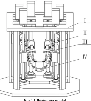
[image:6.595.55.284.326.461.2]As shown in Fig. 11, the prototype of jaw movement robot mainly consists of the static platform I, driving device Ⅱ, branched chain Ⅲ, and mandible platform Ⅳ. The six branched chains should be assembled in the same way, then collectively connect the static and mandible platforms to complete the robot assembly smoothly.
Fig.11 Prototype model
VI. CONCLUSION
By the mechanical bionic principle, considering the jaw size parameters and jaw driving muscles’ biomechanical characteristics of human mandible system, the paper proposes a new jaw movement robot. Compared with the similar robot, it can reconstruct human mandible movement and mechanics characteristics more accurately. Through the motion performance analysis and simulation experiment research, the paper verifies the feasibility of the structure design, the reliability of the movement trajectory, and the rationality of the bite force, which can lay a foundation for the development of the prototype.
REFERENCES
[1] O. Rohrle, A.J. Pullan. Three-dimensional finite element modelling of muscle forces during mastication[J]. Journal of Biomechanics, 2007, 40(15): 3363-3372.
[2] A.C. Hannam. Jaw muscle structure and function[M]. Berlin: C. McNeill, 1997.
[3] Ming Cong, Zhanbo Chang, Yu Du, Weiliang Xu. Modeling and simulation of masticatory robot [C]//Proceedings of 10th IEEE-RAS International Conference on Humanoid Robots. London, England: Springer-Verlag, 2010: 198-203.
[4] K. Alemzadeh, D. Raabe. Prototyping artificial jaws for the bristol Dento-Munch Robo-Simulator[C]//29th IEEE Annual International Conference of EMBS. New York, NY, USA: IEEE, 2007: 1453-1456. [5] M. Callegari, P. Marzetti. Proposal of a mechatronic system for reading
and analysis of jaw movements and denture testing[J]. Healthcare, medical robots and rehabilitation, 2004: 165-171.
[6] C.H. Gibbs, H.C. Lundeen. Jaw movements and forces during chewing and swallowing and their clinical significance[J]. Advances in Occlusion, John Wright, 1981:2-32.
[7] K. Hyodo, et al. Development of the joint simulators applying Ni-Ti shape memory alloy[J]. Seikeigeka Biomechanics, 1985, 7: 231-236. [8] W.L. Xu, J. Bronlund and J. Kieser. A robotic model of human
masticatory system for reproducing chewing behaviours[J]. IEEE Robotics Automation Mag, 2005, 12 (2): 90-98.
[9] W.L. Xu and J. Bronlund. Mastication Robots[M]. Berlin: Springer, Heidelberg, 2010.
[10] C. Bowey, D. Burgess. Robotic temporomandibular joint[R]. Adelaide, University of Adelaide, 2005.
[11] T. Hayashi, S. Tanaka, S. Nakajima, et al. Control mechanism of an autonomous jaw-movement simulator JSN/1C during open–close movement[C]//Proceedings of 18th Annual International Conference of the IEEE Engineering in Medicine and Biology Society. New York, NY, USA: IEEE, 1996:613-614.
[12] T. Hayashi, S. Kato, S. Yamada, et al. A physiological control of chewing-like jaw movement for robotized jaw simulator JSN/2A[C]//Proceedings of the IEEE EMBS International Conference. New York, NY, USA: IEEE, 2000: 730-731.
[13] B. Galer, N. Hockenberry, J. Maloof, et al. Human jaw motion simulator[R]. Boston, Northeastern University, 2007.
[14] H. Takanobu, A. Takanishi, D. Ozawa, et al. Integrated dental robot system for mouth opening and closing training[C]//Proceedings of the IEEE International Conference on Robotics and Automation. New York, NY, USA: IEEE, 2002: 1428-1433.
[15] E. Flores and S. Fels. Design of a 6 DOF antropomorphic robotic jaw[J]. Journal of the Acoustical Society of America, 2005, 117 (4): 2542. [16] J. H. Koolstra, T. M. van Eijden. The jaw open-close movements
[image:6.595.90.249.560.737.2]