Analysis, Design of G +7 Storey Building Structure
with U Boot Beton Slab by using IS Code Method
and Software
Pallavi Vangari1, Imam Usman Shekh2
1
ME II Civil structure student
Abstract: Analysis, Design and Estimation of G +7 Storey Building Structure by using IS Code Methods and by Software's Keyword: SMRF, Seismic behavior and design, Auto-CAD, STAAD Pro, ETABS Revit, Estimation and costing, IS code -Limit State methods
I. INTRODUCTION
Severe damage of buildings in the most distressing consequence of most natural hazards especially earthquake and due to ++. In the past limiting damage was not a prime objective of seismic design codes which concentrated only on providing an adequate level of life safety. Seismic load, wind load, dead load and live load is calculated and applied on structure. From these load combination maximum factor of safety is consider so the structure will not fail during natural hazards or due to overloading. Reinforced concrete special moment frames are used as part of seismic force-resisting systems in buildings that are designed to resist earthquakes. Beams, columns, and beam-column joints in moment frames are proportioned and detailed to resist flexural, axial, and shearing actions that result as a building sways through multiple displacement cycles during strong earthquake ground shaking. STAAD. Pro features a state-of-the-art user interface, visualization tools, powerful analysis and design engines with advanced finite element and dynamic analysis capabilities. From model generation, analysis and design to visualization and result verification. IS codes are used for manual calculations. For manual calculations of G+7 storey building construction limit state method is used. Therefore, it is need of time to analyze & design such hazard resisting structures so as to save human life and avoid property damage.
II. LITERATURE REVIEW
A. Prakash Sangamnerkar et al. (2015). Static and dynamic behaviour of reinforced concrete framed regular building.
He has done the comparative study on the static and dynamic behavior of reinforced concrete framed regular building. Comparison of static and vibrant behaviour of a six storey’s structure is considered in this paper and it is analysed by using computerized solution available in all four seismic zones i.e. II, III, IV and V. This is important for building design and resistant from earthquake.
B. M. S. Aainawala et al. (2014). Comparative study of multi-storey R.C.C. Buildings with and without Shear Walls.
He did the comparative study of multi-storey R.C.C. Buildings with and without Shear Walls. They applied the earthquake load to a building for G+12, G+25, G+38 located in zone II, zone III, zone IV and zone V for different cases of shear wall position. They calculated the lateral displacement and story drift in all the cases. It was observed that Multi-storeyed R.C.C. Buildings with shear wall is economical as compared to without shear wall. As per analysis, it was concluded that displacement at different level in multi-storeyed building with shear wall is comparatively lesser as compared to R.C.C. building without shear wall. Which is important for building design and use of shear walls.
C. P. Rajaram, A. Murugesan, G.S. Thirugnanam (2010).Experimental study and research on behavior of interior RC beam column joint subjected to cyclic loading.
resisting frames for general building using ETABS as per IS 1893-2002 code procedures and detailed as IS 13920-1993 recommendations.
D. Mohit Sharma et. al. (2015). To study the dynamic analysis of multi-storey Building.
He considered a G+30 storied regular reinforced concrete framed building. Dynamic analysis of multi-storey Building was carried out. These buildings have the plan area of 25m x 45m with a storey height 3.6m each and depth of foundation is 2.4 m. & total height of chosen building including depth of foundation is 114 m. The static and dynamic analysis has done on computer with the help of STAAD-Pro software using the parameters for the design as per the IS-1893- 2002-Part-1 for the zones- 2 and 3. It was concluded that not much difference in the values of Axial Forces as obtained by static and dynamic analysis.
E. Anwaruddin M. et. al. Carried out the study on non-linear Static Pushover Analysis of G plus 3 medium rise reinforced cement concrete structure with and without vertical irregularity.
It was seen that irregularity in height of the building reduces the performance point of structure. There was reduction in displacement or deformation of the RCC building also.
III. METHODOLOGY
Process of designing G+7 building structure by using softwares.
FIG 1 Autocad Plan
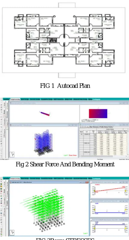
[image:2.612.198.413.309.708.2]Fig 2 Shear Force And Bending Moment
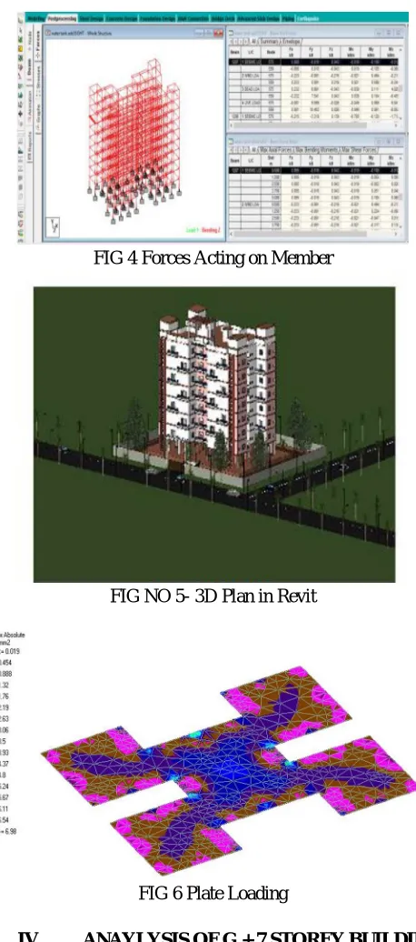
FIG 4 Forces Acting on Member
FIG NO 5- 3D Plan in Revit
FIG 6 Plate Loading
IV. ANAYLYSIS OF G + 7 STOREY BUILDING
1) Material Properties: The analysis has been done considering the following material properties
a) Structural Steel: Tor steel
b) Reinforced Concrete: Reinforced concrete of design mix with grade M 20
c) Steel Reinforced: Fe 415
d) Stirrups and Links: Fe 415
2) Load Calculation: Following assumption are made for load calculation
a) Density of concrete: 20kN/m3
b) Density of brick: 18kN/m3
e) Thickness of wall: 230mm
f) Thickness of brickbat coba : 150mm
g) Floor finish load: 1kN/m
h) LL on floor slabs: 3kN/m2
3) Evaluation of Loads
a) Dead load of slab=
b) 0.20x1x25 = 5 kN/m
c) LL on floors = 3X1 =3kN/m
V. DESIGN AND ANALAYSIS OF G+7 STOREY BUILDING USING STAAD PRO
A. Introduction
Our project is based on the design and analysis of the multi-storied buildings Analysis is done through using the STAAD- PRO Notation adopted through out the project is same as in IS-456-2000
[image:4.612.195.416.276.364.2]CODES IS-456:200 :DESIGN CODE FOR RCC STRUCTURES SP-16 : DESIGN CODE FOR COLUMNS IS-875(PART 1) :CODE FOR DEAD
Table 1 Seismic Zones of India Showing % Town Area LOADS IS-875(PART 2) :CODE FOR IMPOSED LOADS
IS-875(PART 3) :CODE FOR WIND LOADS
B. Softwares
This project is mainly based on software and it is essential to know the details about these software’s
1) Staad pro(v8i)
2) AUTOCAD
3) ETABS
4) ESTIMATION AND COSTING
C. Staad
(Staad stands for structural analysis and design)
1) Staad is the powerful design software licensed by bentley . Staad stands for structural analysis and design
2) To calculate S.F.D and B.M.D of complex loading beam it takes about an hour.
3) So when it comes up to building with several members it will taken a week.
4) Staad pro is a very powerful tool which it does this job in just an hours staad is a best alternative for high rise buildings.
5) Now a days most of the high rise buildings are designed by staad which makes a compulsion for a civil engineer to know about
this software.
D. Auto Cad
Auto cad is powerful software licensed by auto desk company and cad stand for computer aided design.
1) It is used for drawing different layouts, elevations, details, sections different sections can be shown in auto cad.
2) We used for drawing the plan of multi stored building.
3) It is very useful for civil, mechanical, and also electrical engineer.
E. ETABS
F. Statement of The Project
1) Utility of building: Residential building
2) No of storeys :G+7
3) No.of staircases: 8 no's
4) Shape of the building: Rectangular
5) Type of construction: R.C.C framed structure 5.Type of walls :brick wall
a) Floor height :3.2M
b) Height of plinth: 2M from below foundation
c) Depth of foundation: 700MM
d) Material details: Concrete Grade: M20
e) All steel grade: Fe415 grade
f) Type of steel bars: HYSD
g) Bearing capacity of Soil : >180 KN/M2
G. Different Types Of Loads On The Structures
Dead loads Imposed loads Wind loads
Dead loads Involves self weight of RCC slab Beams & columns Plinth Wall
Imposed loads: Imposed also known live loads. Loads over the floor i.e. Load of persons it is calculated as 1 KN/m2. This load is applied over the length of structure
Wind loads Wind is air in motion Wind loads are calculated according to IS:875(part 3) Intensity of wind and exposure are applied in the direction as required
Load combinations The structures should be analysed for combination of loads as in practice we have numbers of loads in various directions act Some of the combinations to be checked are 1.5(DL+LL) 1.5(DL+WL) 1.5(DL+LL+WL)
H. Objectives Of Strucural Deign
Structure designed should satisfy the criteria of ultimate strength. Structures should satisfy the serviceability. It should satisfy the stability against overturning, sliding, and buckling
The main objective of the design are Foundation design Column design
Beam design Slab design
DESIGN PRINCIPLE, ASSUMPTION AND NOTATION ASSUMED
Top cover 25
Aggregate size 40
Bottom cover 25
Concrete grade M20 Side cover 25
Beam segments 12
Main Bar Criteria Top Bar Criteria Bottom Bar Criteria Min. bar size 8 8
Max. bar size 40 40
Link hanger size 8 8
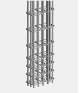
FIG 7 BEAM REINFORCEMENT
I. Analysis
Analysis is done using STAD PRO developed by BENTLEY Once the loads and load combinations are assigned to the structures, analysis is to be done Analysis is done for RCC structure
1) Assign the properties of structures
2) Assign loads on the slab
3) Load assign on the walls
4) Assign wind load on the structures (x+ve direction)
5) Assign wind load on the structures (x-ve direction)
6) Assign wind load on the structures (z +ve direction)
7) Assign wind load on the structures (z -ve direction)
RCC analysis Code is assigned as IS: 456-2000 The parameters are assigned to the structure Commands to be given are 1. Concrete design 2.define parameters 3. Command
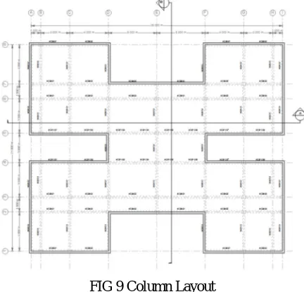
[image:6.612.185.438.398.696.2]FIG 9 Column Layout
Shear design results at distance d (effective depth) from face of the support
shear design results at 535.0 mm away from start support vy = 9.40 mx = -0.02 ld=1 provide 2 legged 8í @ 140 mm c/c shear design results at 535.0
mm away from end supportvy = 9.40 mx = -0.02 ld=1 provide 2 legged 8í @ 140 mm c/c
TABLE NO 2 COLUMN – BAR SCHEDULE
TABLE NO 3 SHEAR BAR CRITERIA
[image:7.612.113.478.334.719.2]VI. ONCLUSIONS
The design of slab, beam, column, rectangular footing and staircase are done in limit state method which is safe at control of deflection and in all aspects Using staad.pro software, the design consideration has been taken as per the is codes. The design is safe in all conditions On comparison with drawing, manual design and the geometrical model using staad.pro the area of AST required for the beam, column, footing and slab are comparatively similar to that of the requirement.
while software also gives required sizes of bar and members but with factor of safety.
Auto-cad plan gives detailed information of the structure members length, height, depth, count etc.
After running model in Revit software it gives more plan details and various design options. This software gives more decorative building structure.
STAAD PRO has the capability to calculate the reinforcement needed for any concrete section. The program contains a number of parameters which are designed as per IS: 456(2000). Beams are designed for flexure, shear and torsion.
From the STAAD PRO result required different types, size and number of bars are found. And final evaluation and valuation is confirmed by estimation and costing software.
[image:8.612.149.453.465.601.2]Due to manual and software calculations, the required amount and material will be minimized so the structure comes under healthy for environment and safe for human beings.
Table NO 6 Slab Reinforcement
Table NO 7 Beam- Main Bar Criteria
VII. SCOPE FOR FURTHER STUDIES
A. All the analysis can be repeated by changing plan dimensions and height of the structure.
B. A comparison of cost may be studied by changing different grade of steel and concrete.
C. Analysis and design of frames with dual systems.
D. Analysis and design of frames with dual systems (moment resisting frames with shear walls)
REFERENCES [1] Ashok Jain, Limit state design.
[2] Fischer Gregor and C. Li Victor, (2003) intrinsic response control of moment resisting frames utilizing advanced composite materials and structural elements. ACI structural Journal V.100, N0.2.
[3] Indian Standard Code Of Practice For Ductile Detailing Of Reinforced Concrete Structures To Seismic Forces IS: 13920-1993, Indian Standard Institute, New Delhi.
[4] Indian Standard Code Of Practice For Plain And Reinforced Concrete IS: 456-2000 Indian Standard Institute, New Delhi. [5] Indian Code For Resistant Design Of Structures IS: 1893-2002 Indian Standard Institute, New Delhi.
[6] Uma S.R. and Prasad Meher A.,(2003) Analytical Model For Beam Column Joints In R/C Moment Resisting Frames Pacific Conference On Earthquake Engineering.Rajaram P.,(2010),Behaviour Of Interior Beam Column Joint Subjected To Cyclic Loading.
[7] Prakash Sangamnerkar et al. International Research Journal Of Engineering And Technology (IRJET) Volume:02 Issue: 04 | July-2015. [8] Piyush Tiwari et al. 07 Oct 2015 International Research Journal Of Engineering And Technology (IRJET).
[9] Dr. S.R. Karve & Dr. V.L. Shah - “Illustrated design of Reinforced concrete Buildings” [10] N. Krishna Raju - “Advanced Reinforced Concrete design”
[11] “STAAD Pro 2004 – Getting started & tutorials” - Published by: R .E. I. [12] “STAAD Pro 2004 – Technical reference manual” - Published by: R.E.I.
BIBLIOGRAPHY
[1] Structural analysis by S.RAMAMRUTHAM For load calculation on structure by pankaj agrawal IS456-2000 CODE used SP16 CODE used AUTO CAD & STAAD PRO packages