Orcad
®
Layout
Cadence PCB Systems Division Trademarks
Allegro, Ambit, BuildGates, Cadence, Cadence logo, Concept, Diva, Dracula, Gate Ensemble, NC Verilog, OpenBook online documentation library, Orcad, Orcad Capture, PSpice, SourceLink online customer support, SPECCTRA, Spectre, Vampire, Verifault-XL, Verilog, Verilog-XL, and Virtuoso are registered trademarks of Cadence Design Systems, Inc.
Affirma, Assura, Cierto, Envisia, Mercury Plus, Quickturn, Radium, Silicon Ensemble, and SPECCTRAQuest are trademarks of Cadence Design Systems, Inc.
Alanza is a service mark of Cadence Design Systems, Inc.
All other brand and product names mentioned herein are used for identification purposes only and are registered trademarks, trademarks, or service marks of their respective holders.
Part Number 60-30-650 Second edition 31 May 2000
Cadence PCB Systems Division (PSD) offices
PSD main office (Portland) (503) 671-9500
PSD Irvine office (949) 788-6080
PSD Japan office 81-45-682-5770
PSD UK office 44-1256-381-400
PSD customer support (877) 237-4911
PSD web site www.orcad.com
PSD customer support web page www.orcad.com/technical/technical.asp
Contents
Before you begin v
Welcome to OrCAD . . . v
How to use this guide . . . vi
Symbols and conventions . . . vi
Introduction to autorouting 1
Chapter 1
Gridded autorouter . . . 2Sweep technology . . . 2
Shove technology . . . 2
Interactive routing tools . . . 3
Gridless shape-based autorouter . . . 3
Using autorouting and interactive routing 5
Chapter 2
Loading a routing strategy file . . . 7Routing power and ground on predominantly through-hole boards . . . 8
Fanout on boards with surface mount devices . . . 10
Implementing power and ground fanout . . . 11
Implementing full board fanout . . . 14
Using interactive routing tools . . . 15
Using shove track mode . . . 15
Using auto path route mode . . . 17
Pre-routing critical nets . . . 18
Autorouting a board . . . 19
Disabling power and ground . . . 19
Running the autorouter . . . 19
Generating test points automatically . . . 20
Routing single-sided boards . . . 23
Using routing strategy files 29
Chapter 3
Editing strategy files . . . 30
Editing route sweep parameters . . . 31
Editing route pass parameters . . . 34
Editing route layer parameters . . . 38
Editing route spacing parameters . . . 40
Before you begin
Welcome to OrCAD
OrCAD offers a total solution for your core design tasks: schematic- and VHDL-based design entry; FPGA and CPLD design synthesis; digital, analog, and mixed-signal simulation; and printed circuit board layout. What’s more, OrCAD’s products are a suite of applications built around an engineer's design flow—not just a collection of
How to use this guide
The OrCAD Layout Autorouter User’s Guide contains information about autorouting in OrCADLayout and Layout Plus.
To help you learn and use the autorouter efficiently, this manual is separated into the following sections:
• Introductin to autorouting discusses Layout’s two
autorouting options: a gridded autorouter, and a gridless, shape-based autorouter.
• Using autorouting and interactive routing explains
how to prepare a board for autorouting, how to route a board using autorouting, and how to otptimize autorouting results usnig interactive routing tools.
• Using routing strategy files discusses the purpose and
use of routing strategy files.
Symbols and conventions
OrCAD printed documentation uses a few special symbols and conventions.
Notation Examples Description
C+r Press C+r Means to hold down the C key while pressing r.
A, f, o From the File menu, choose Open (A, f,
o)
Means that you have two options. You can use the mouse to choose the Open command from the File menu, or you can press each of the keys in
parentheses in order: first A, then f, then o.
How to use this guide
vii UPPERCASE In Capture, open CLIPPERA.DSN. Path and filenames are shown in
uppercase. In the example, you open the design file named CLIPPERA.DSN. Italics In Capture, save design_name.DSN. Information that you are to provide is
Introduction to autorouting
1
Gridded autorouter
Layout’s gridded autorouter has two key features: sweep technology, which allows you to specify the directional emphasis for routing different boards, and shove
technology, which minimizes vias and allows extremely dense autorouting. In addition, you can use interactive routing tools (see Interactive routing tools below) with the gridded autorouter to refine the process of autorouting.
Sweep technology
The autorouter routes the board using sweeps, which are successive routing passes. Beginning at a specified point, Layout routes the board continually according to the sweep direction you specify. For example, if you want the sweeps to progress up first and then to the left, the autorouter routes vertically and then horizontally, working through the entire board.
Shove technology
The autorouter finds the optimal space for a given track and then moves or “shoves” other tracks out of the way before routing in that area. If a pad or via is blocking the routing path, then the autorouter attempts to go around the blockage by routing to a different layer using a via. The autorouter also checks to see if there are obstructing tracks that can be rerouted or moved to an entirely different location on the board.
Gridless shape-based autorouter
3
Interactive routing tools
Though not part of the autorouter itself, interactive routing tools complement the gridded autorouter by allowing you to refine an autorouted board. Using auto path route mode and shove track mode, you can route critical nets and dense boards with minimal effort.
Gridless shape-based autorouter
Layout Plus provides a gridless shape-based autorouter called SmartRoute. Exclusive to Layout Plus, SmartRoute has fast routing speeds, high completion rates, and high router quality.For information on auto path route mode and shove track mode, see Using interactive routing tools on page 15.
Using autorouting and
interactive routing
2
This chapter explains how to prepare a board for
autorouting, how to route a board using autorouting, and how to optimize autorouting results using interactive routing tools.
Note
This chapter describes processes and modes relevant to autorouting
and interactive routing tools. Layout commands and modes for
manual routing are covered in Chapter 8, Routing the board in the
OrCAD Layout User’s Guide.
You probably performed the following tasks when you set up the board and placed components. If not, you need to do so to prepare the board for routing.
n Designate appropriate layers as plane layers or
routing layers
n Define vias
n Set or verify net properties
n Run Placement Spacing Violations and correct any
Note
For information on designating plane layers, defining vias, and
setting net properties, see Chapter 4: Setting up the board in the
OrCAD Layout User’s Guide. For information on running Placement
Spacing Violations, see Chapter 7: Placing and editing components
in the OrCAD Layout User’s Guide.
After you have completed the above items, you are ready to begin the routing process. The steps in the autorouting process are:
n Check the board outline, via definitions, and routing
and via grids
n Load a routing strategy file
n On predominantly through-hole boards, verify
connections to the planes
n On SMT boards, implement fanout for power and
ground
n Pre-route critical nets
n Implement autorouting
n Optimize routing using the interactive routing tools
n Check for route spacing violations and check routing
statistics
n Optimize routing using Layout’s routing commands
For information on checking for route spacing violations and checking routing statistics, see Checking routing in Chapter 8, Routing the board in the OrCAD Layout User’s Guide.
Loading a routing strategy file
7
Loading a routing strategy file
A routing strategy file determines which default routing layers to use, when to use vias, which direction the track should travel, which colors to use for routes, and the size of the active routing window. There are many routing strategy files provided with Layout, among which are files for two-layer, four-layer, six-layer, and eight-layer boards. Load the routing strategy file that is most suitable for your board.
Note
For a complete list of the routing strategy files provided with
Layout, see Strategy files in Appendix A, Understanding the files
used with Layout in the OrCAD Layout User’s Guide.
To load a routing strategy file
1 From the File menu, choose Load. The Load File
dialog box displays.
2 If necessary, change Files of type to Strategy.
3 Select a routing strategy file (.SF), then choose the OK
button.
Routing power and ground on
predominantly through-hole
boards
If you are working with a through-hole board, you must verify that all power and ground nets are connected to the proper plane layers before autorouting. If they are not, you must complete these connections (for example, an edge finger needs to be routed to a via for connection to the plane).
On through-hole boards, the appropriate nets are automatically attached to the plane layers with thermal reliefs. If the power or ground nets did not connect to the plane layers, one of three errors may have occurred in the netlist:
n The global power pin is not defined in the part.
n The pin is not connected to the proper signal.
n If the pin is connected, it does not have the correct
signal name.
To remedy the problem, either modify the schematic and annotate it again, or modify the board by adding a pin to the signal. Keep in mind that this board modification cannot be back annotated to the schematic.
Layout automatically recognizes nets that have been properly connected to plane layers by making these nets invisible. You may also use the Nets spreadsheet to verify connections to plane layers prior to post processing.
If the board has a split plane, you can verify that the power and ground nets are properly connected to the
appropriate plane areas by viewing the plane layers. If power and ground display as thermal reliefs, then they are indeed connected.
Routing power and ground on predominantly through-hole boards
9 Note
For information about split planes, see Creating split planes in
Chapter 8, Routing the board in the OrCAD Layout User’s Guide.
You can also view the thermal connections using the post process
preview. For information about viewing thermal reliefs, see
Previewing thermal reliefs in Chapter 9: Using thermal reliefs and
copper pour zones in the OrCAD Layout User’s Guide.
Connections to the planes can be verified prior to post processing by verifying that only nets connected to the planes are enabled, then viewing the Statistics
spreadsheet to verify that these nets are 100% routed.
To verify connections to the planes
1 Choose the spreadsheet toolbar button, then choose
Statistics. The Statistics spreadsheet displays.
2 If necessary, respond to the message asking if you
want to repour copper by choosing the Yes button.
3 Scroll until you find the Routed row, which is the
beginning of the routing data. You should see a value of 100% in the Enabled column for % Routed, which indicates that the appropriate nets are connected to the plane layers.
4 If the value is anything less than 100%, choose the
refresh all toolbar button.
5 If the value is still anything less than 100%, minimize
the Statistics spreadsheet, choose a routing tool, and route the net to the appropriate plane layer.
6 Maximize the Statistics spreadsheet, then choose the
refresh all toolbar button.
7 After you’ve verified that the value in the Enable
Fanout on boards with surface
mount devices
Before routing a board with surface mount devices (SMDs), you must perform fanout to connect the power and ground nets to the plane, then run Design Rule Check (DRC) to verify that fanout is complete.
Fanout is a method for facilitating route operations for surface mount pads on a board. It is the process of routing an SMD pin to a via so that the connection to the
component can be routed on other layers. For power and ground pads, the target via is attached to a power or ground plane using a thermal relief.
Fanout is especially useful for:
n Multilayer boards that include power and ground
planes
n Densely packed boards that do not permit routing on
surface layers
n Boards that include fine-pitch components that
impede surface routing
Fanout is commonly used to route the power and ground layers of an SMT board. However, you can also perform full board fanout, which is sometimes helpful for routing dense, multilayer SMT designs.
Layout has three fanout commands: Board, DRC/Route Box, and Component.
n Board implements fanout for the entire board.
n DRC/Route Box implements fanout for all SMD
components within the DRC/Route Box (represented on screen by a rectangle with a dashed border).
n Component implements fanout for a selected SMD
Fanout on boards with surface mount devices
11
Each command performs fanout on a different scale: at the board level, a user- specified area (the DRC/Route Box) and the component level. You can modify options for all three within the Fanout Settings dialog box (available by choosing Fanout Settings from the Options menu).
Implementing power and ground fanout
Power and ground fanout must occur before any signal routing. Power and ground fanout connects all surface mount power and ground pins to the appropriate plane layer. This is done by means of a via that extends to the thermal relief connection.
Before you implement power and ground fanout, you must assign the power and ground nets to plane layers so that the router will recognize these nets as voltage nets rather than signal nets.
To fanout power and ground
1 From the Options menu, choose Fanout Settings. The
Fanout Settings dialog box displays.
2 Select the Fanout Power/Gnd option and your choice
of the options under it. (See the description of the options in this chapter.)
3 Deselect the Fanout Signals option.
4 If you want fanout to place vias inside (or under)
SMDs, select the Inside option.
5 If you want fanout to place vias outside SMDs, select
the Outside option.
6 In the Maximum Fanout Distance text box, specify the
maximum distance from the SMD pad to the fanout via, then choose the OK button.
7 From the Auto menu, choose Fanout, then choose
Board.
8 From the Auto menu, choose Design Rule Check. Select the SMD Fanout Violations option in the Check Design Rules dialog box, then choose the OK button.
9 If necessary, use the interactive routing modes to route
all fanout failures (such as No Connection to Plane), using the error markers as a guide.
10 Repeat steps 7 through 9 until all power and ground
[image:20.612.236.387.260.513.2]pins are properly fanned out.
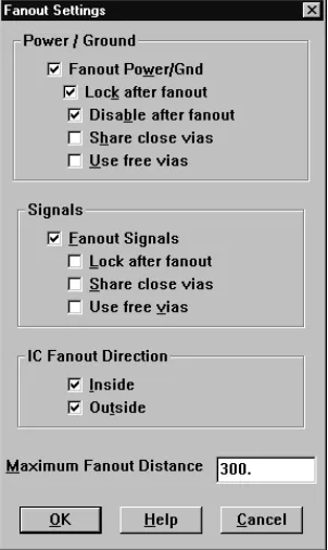
Figure 1 The Fanout Settings dialog box
Fanout Power/Gnd
Determines whether Layout implements fanout for power and ground SMD pads. Power and ground pads are identified by being enabled on an appropriate plane layer, as shown in the Nets spreadsheet.
Lock after fanout. Locks the fanout tracks and vias for For instructions on using the interactive
Fanout on boards with surface mount devices
13
Disable after fanout. Prevents power and ground nets from being routed after fanout is complete. This is especially advantageous if you plan to perform autorouting immediately after fanout is complete. If fanout fails to complete all pads for the power and ground nets that are enabled, a message displays to that effect.
Share close vias. Permits tracks belonging to the same power or ground net to share a single via. Use discretion before selecting this option: via sharing can result in long fanout tracks or large currents.
Use free vias. Permits the use of free vias for optimal implementation of power and ground fanout. If this option is not selected, regular vias are used.
Fanout Signals
Determines whether Layout implements fanout for signals connected to SMD pads. A signal is any net that is not enabled on a plane layer.
Lock after fanout. Locks the signal tracks and vias after fanout is complete. In general, it is best to leave signal tracks unlocked, so the autorouter can move them as necessary to finish routing the board.
Share close vias. Permits tracks belonging to the same signal to share a single via. Via sharing for signals reduces the number of vias on (and, therefore, the congestion of) the board.
Use free vias. Permits the use of free vias for optimal fanout of signals connected to SMD pads. If this option is not selected, regular vias are used.
Inside
Allows Layout to place fanout vias inside (or under) the SMD.
Outside
Maximum Fanout Distance
The value you set for this option determines the
maximum distance from an SMD pad to a fanout via. This distance is the Euclidean distance (measured from the center of the SMD pad), not the cumulative distance of the associated track segments. By default, the value for this option is 300 (mils).
Note
Layout places vias on grid points only. If there is no grid point
within the maximum distance you specified, a via may be placed on
a grid point beyond this distance.
Implementing full board fanout
It is not necessary to implement fanout for all pads that are not connected to power and ground, because the router can route pads for which it could not place a fanout via. For multilayer SMD boards, you should normally let the router determine via locations, rather than implement fanout. The sheer number of vias created with fanout can block too many channels for the router to work efficiently, especially on dense SMD boards.
However, for fine pitch components, it is useful to run component fanout, since this is typically the only way you can fanout all pins without blocking off one or more pins in the process.
Before you implement full-board fanout, ensure that power and ground are disabled for routing and that all other signals are enabled.
To complete full board fanout
1 From the Options menu, choose Fanout Settings. The
Fanout Settings dialog box displays.
2 Deselect the Fanout Power/Gnd option.
Using interactive routing tools
15
4 If you want fanout to place vias inside (or under)
SMDs, select the Inside option.
5 If you want fanout to place vias outside SMDs, select
the Outside option.
6 In the Maximum Fanout Distance text box, specify the
maximum distance from the SMD pad to the fanout via, then choose the OK button.
7 From the Auto menu, choose Fanout, then choose
Board.
Using interactive routing tools
Online DRC (design rule check) is automatically activated whenever you choose either of the interactive routing tools (shove track or auto path route). In addition, you can only use the interactive routing tools on connections within the DRC box.Shove track mode is considered interactive routing because you are interacting with the automatic
push-and-shove routing capabilities of Layout when you are routing a track.
Auto path route mode (not available in Layout Engineer’s Edition) is considered interactive routing because you are interacting with the autorouter when it suggests tracks and suggests via placement (if you select the Suggest Vias option in the Route Settings dialog box).
Using shove track mode
When you use shove track mode, Layout shoves other tracks out of the way of the track that you are currently routing. With this mode, you can pick up individual connections and route them aided by the shove capability, manually route critical tracks, and edit tracks and vertices.
To set routing parameters for shove track mode
1 From the Options menu, choose Route Settings. The
Route Settings dialog box displays.
2 Select the Shove Track Mode option, select one of the
following options, then choose the OK button.
Low Power The router moves tracks only slightly, or conservatively, in an attempt to move them out of the way as you add new tracks.
Medium Power The router shoves tracks, and may even push routes over other items (such as pads) and around other tracks in an attempt to move them out of the way as you add new tracks.
High Power The router rips up, shoves, and reroutes existing tracks as you add new tracks.
To use shove track mode
1 Choose the shove track toolbar button.
2 Define the DRC box size to encompass your area of
interest.
3 Select a connection with the left mouse button. The
connection attaches to the pointer.
4 Drag the pointer to draw a track on the board.
5 Click the left mouse button or press the SPACEBAR to
create vertices (corners) in the track.
6 When drawing the last segment for the connection,
choose Finish from the pop-up menu. The track automatically connects to the center of the pad. A complete connection is indicated by the cursor changing size and the ratsnest disappearing from the pointer.
Using interactive routing tools
17 Tip
While routing, if you press the
ALTkey and click the left mouse
button on a track, you can begin a new track on another track of
the same net, which is known as T-routing.
Using auto path route mode
When you use auto path route mode (not available in Layout Engineer’s Edition), Layout suggests a possible track when you select a ratsnest or pin. As you move the cursor, the suggested track changes position. When you click the left mouse button, auto path route mode places the suggested track using the push-and-shove routing capabilities of the autorouter, thereby clearing away any imposing tracks. Note that the final track may not look like the suggested track. You can only use auto path route mode with online DRC enabled. Attempting to disable online DRC takes you out of auto path route mode.
When you use auto path route mode with the Suggest Vias option selected in the Route Settings dialog box (from the Options menu, choose Route Settings), Layout displays potential via locations as you’re routing, and removes them if they’re not needed in the final version of the track.
To set interactive autorouting options for auto path route mode
1 From the Options menu, choose Route Settings. The
Route Settings dialog box displays.
2 Select the Auto Path Route Mode option, select one of
the following options, then choose the OK button.
Allow Off-Grid Routing This option allows auto path route mode to display possible routing paths without regard to the routing grid. Selecting this option is the only way to permit auto path route mode to end tracks at an obscure angle of approach. Off-grid routing is almost always needed for mixed-pitch boards.
Shove Components This option allows auto path route mode to shove components in much the same way as it shoves tracks. That is, when you place a
vertex using the left mouse button or SPACEBAR, any
imposing components are moved away from the vertex (unless those components are locked).
Maximize 135 Corners This option allows auto path route mode to optimize routing space with vertices of 135° or 90°. If deselected, the autorouter creates 90° corners only.
Pre-routing critical nets
Before autorouting, you should route critical nets manually and lock them to the board.
To route a critical net
1 Choose an interactive routing tool and route a critical
net by following the instructions given in To use shove
track mode earlier in this chapter.
To lock a critical net
1 Choose the spreadsheet toolbar button, then choose
Nets. The Nets spreadsheet displays.
2 Select the appropriate row using CTRL and the left
mouse button.
Autorouting a board
19
Autorouting a board
Once you’ve routed the power and ground nets, you should disable them for routing, and enable the other nets on the board for routing.
Disabling power and ground
To disable the power and ground nets and enable other nets
1 Choose the spreadsheet toolbar button, then choose
Nets.
2 Click once in the title cell of the Routing Enabled
column. The entire column is highlighted.
3 From the pop-up menu, choose Enable<->Disable.
The Routing Enabled for the VCC and GND nets changes to No*, and the Routing Enabled changes to Yes for the rest of the nets.
Running the autorouter
The autorouter initiates a series of routing passes that systematically route an entire board.
Tip
Before you begin routing the board, save your board file.
The routing strategy file you loaded determines which passes are performed on your board during autorouting. You can see which passes are enabled and alter the number of passes performed using the Route Pass spreadsheet.
The autorouter begins its initial pass inside the DRC box. By default, the DRC box is located on the densest area of a board. You may choose, however, to customize and specify the size and location of the DRC box.
Each pass is described and the process for enabling passes is explained in Editing route pass parameters on page 34.
To run the autorouter
1 From the Auto menu, choose Autoroute, then choose
Board. The autorouter runs the passes specified by the routing strategy file you loaded.
2 Either run additional passes on the board, or optimize
the board using Layout’s interactive routing tools.
Generating test points
automatically
Before you can have Layout generate test points
automatically, you must specify which vias and nets you want to use for this purpose. Having done this, you can run the test point routine, which adds test points to vertices (corners) on relevant nets. After Layout completes this process, you can check the board for test point violations and create an index of test points in a test points text file (*.TXT).
Note
Do not use Via 1 as a test point. It is used as the default by the
router.
To generate test points automatically
1 Choose the spreadsheet toolbar button, then choose
Padstacks. The Padstacks spreadsheet displays.
2 Select a cell in the Padstack or Layer Name column
that contains the name of a via that shows all layers as Undefined. All of the cells pertaining to that particular via are highlighted in black.
3 From the pop-up menu, choose Properties. The Edit
Padstack dialog box displays.
Generating test points automatically
21
5 Choose the spreadsheet toolbar button, then choose
Nets. The Nets spreadsheet displays.
6 Using the left mouse button and the CTRL key, select
nets that need test points.
7 From the pop-up menu, choose Properties. The Edit
Net dialog box displays.
8 Select the Test Point option, then choose the OK
button. Close the Nets spreadsheet.
9 Route the board to completion.
10 From the Options menu, choose Test Point Settings.
The Test Point Settings dialog box displays.
11 Select the options of your choice (see the description of
the options in this chapter), then choose the OK button. Layout places test points on each of the nets you specified.
12 From the Auto menu, choose Design Rule Check. The
Check Design Rules dialog box displays.
13 Choose the Clear All button, then select Test Point
Violations and choose the OK button. Layout notifies you of any errors that were found.
14 Correct any test point violations.
15 From the Auto menu, choose Create Reports. The
Generate Reports dialog box displays.
16 Select the Test Points option, select the Save As File
option, then choose the OK button. The TPOINT.TXT file is created.
17 From the File menu, choose Text Editor. A Notepad
window displays.
18 From the Notepad window’s File menu, choose Open.
19 Locate and select the TPOINT.TXT file, then choose
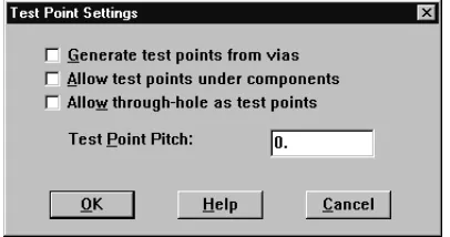
Figure 2 Test Point Settings dialog box
Generate test points from vias
When selected, this option creates test points from vias that are defined in the Padstacks spreadsheet.
Allow test points under components
When selected, this option allows Layout to position newly created test points under board components. If you do not select this option, Layout can only place test points outside of component outlines.
Allow through-hole as test points
When selected, this option allows Layout to use through-hole pins as test points.
Test Point Pitch
Routing single-sided boards
23
Routing single-sided boards
When routing a single-sided board, start with a netlist and a technology template optimized for single-sided boards. Layout provides three such technology templates: JUMP5535.TCH, JUMP6035.TCH, and JUMP6238.TCH. After you create a new board, you must create a board outline (technology templates do not contain board outlines), place the board, and load a strategy file that allows for jumper wires. Two strategy files for jumper wires are provided with Layout. They are JUMPER_H.SF (for horizontal jumpers) and JUMPER_V.SF (for vertical jumpers). You can also create a single-sided board using an existing board file. This section describes both
processes.
To route a single-sided board starting from a netlist
1 Choose the library manager toolbar button. The
library manager displays.
2 Create route keepouts for all of the footprints that will
be placed on the jumper layer (this keeps the jumper vias outside of the components) by selecting a library and a part in the library manager. The relevant footprint displays in the footprint editor.
3 Select the place outline of the footprint by clicking on
it with the left mouse button. Choose Copy from the pop-up menu, then choose Properties from the pop-up menu. The Edit Obstacle dialog box displays.
4 Select an Obstacle Type from the drop-down list, then
choose the OK button.
5 Place the route keepout on the jumper layer.
6 When opening a new board, select one of the
following technology templates in the Load File dialog box: JUMP5535.TCH, JUMP6035.TCH, or
JUMP6238.TCH.
7 Create a board outline, and set up other desired board
criteria using the instructions in Chapter 4, Setting up
the board in the OrCAD Layout User’s Guide.
Note Do not permanently alter or modify any standard footprints. Use the Save As command in the library manager to create new footprints.
For information on editing and copying obstacles, see Editing obstacles and Copying obstacles in Chapter 5, Creating and editing obstacles in the OrCAD Layout User’s Guide. For information on the library manager, see Chapter 14, Creating and editing footprints in the OrCAD Layout User’s Guide.
8 Open the Layers spreadsheet and double-click on the jumper layer. The Edit Layer dialog box displays.
9 Choose the Jumper Attributes button. The Jumper
Lengths dialog box displays.
10 Enter the appropriate values, then choose the OK
button.
11 Select preplaced components by pressing CTRL and
clicking the left mouse button. Press L to lock the
components in position.
12 Place the rest of the board.
13 From the File menu, choose Load. The Load File
dialog box displays.
14 Select one of the two jumper strategy files:
JUMPER_H.SF (for horizontal jumpers) or
JUMPER_V.SF (for vertical jumpers). You should choose the strategy that corresponds to the longer axis of your board (horizontal or vertical). Choose the Open button.
15 Adjust the DRC box to encompass the entire board. If
this is not possible, make the DRC box as large as possible.
16 Route the board.
17 From the Options menu, choose Jumper Settings. The
Jumper Lengths dialog box displays.
18 Enter the appropriate data, then choose the OK
button.
19 From the Tool menu, choose Jumper, then choose
Convert to Components. All of the jumpers created during routing are automatically converted into jumper components, and display both in the parts list and on the silkscreen layer.
Routing single-sided boards
25
To route a single-sided board starting with an existing board file
1 Choose the spreadsheet toolbar button, then choose
Layers. The Layers spreadsheet displays.
2 Double-click on the row of the layer that you want to
designate as a jumper layer. The Edit Layer dialog box displays.
3 Select the Jumper Layer option, then choose the OK
button. The router automatically creates a jumper on that layer, if needed.
4 In the Layers spreadsheet, double-click once again on
the layer that is now designated as the jumper layer. The Edit Layer dialog box displays.
5 Choose the Jumper Attributes button. The Jumper
Lengths dialog box displays.
6 Enter the appropriate data, then choose the OK
button.
7 Secure components that must stay in their current
position on the board by selecting them and choosing Lock from the pop-up menu. This locks the
components on the board.
8 Create route keepouts for all of the components on the
jumper layer (to keep the jumper vias outside of the components). The easiest way to do this is to make a copy of the place outline and define the copy as a route keepout using the Edit Obstacle dialog box. Then, place the route keepout on the jumper layer.
9 From the File menu, choose Load. The Load File
dialog box displays.
10 Select one of the two jumper strategies: JUMPER_H.SF
(for horizontal jumpers) or JUMPER_V.SF (for vertical jumpers). You should choose the strategy that
corresponds to the longer axis of your board (horizontal or vertical). Choose the Open button.
11 Adjust the DRC box to encompass the entire board. If
this is not possible, make the DRC box as large as possible.
12 Route the board.
13 From the Options menu, choose Jumper Settings. The
Jumper Lengths dialog box displays.
14 Enter the appropriate data, then choose the OK
button.
15 From the Tool menu, choose Jumper, then choose
Convert to Components. All of the jumpers created during routing are automatically converted into jumper components, and display both in the parts list and on the silkscreen layer.
Creating jumpers for single-sided boards
Using the Convert to Components command, you can replace “fake” jumpers with jumper components selected from the footprint library.
To create jumpers for single-sided boards
1 Choose the spreadsheet toolbar button, then choose
Layers. The Layers spreadsheet displays.
2 Double-click in the row of the layer that you want to
designate as a jumper layer. The Edit Layer dialog box displays.
3 Select the Jumper Layer option, then choose the
Jumper Attributes button. The Jumper Lengths dialog box displays.
4 Set options to specify the jumper lengths, footprints,
direction and designator, then choose the OK button twice to close the dialog boxes. Close the Layers spreadsheet.
5 From the Tool menu, choose Jumper, then choose
Routing single-sided boards
27
Error markers are created wherever Layout is unable to find a suitable jumper component for a via pattern that exists on the board, or if component-to-component violations are created in the process of inserting the jumpers.
Layout replaces the padstacks originally assigned to the jumpers with the padstacks assigned to the vias that were used during routing, as long as you use the default jumper padstack name J1.
Using routing strategy files
3
Routing strategy files determine which default routing layers to use, when to use vias, in which direction the track should travel, and the size of the active routing window. They also set up the appropriate graphical display for routing. This chapter lists and describes the routing strategies included with Layout, and explains how to edit routing strategy files.
The parameters for the strategy files provided with Layout are set according to the type of board (component type and number of layers) for which the strategy file is intended. In most circumstances, these parameters do not need to be changed. Changing the parameters can
negatively affect routing results.
Editing strategy files
The strategy files are based on information in four sets of data: sweep parameters, pass parameters, layer
parameters, and spacing parameters. You can view these four data sets in spreadsheet form by using the
spreadsheet toolbar button. By editing the parameters in these spreadsheets, you can create new strategy files (.SF) and edit the existing strategy files that drive autorouting. The spreadsheets are listed below.
Route Sweep
Using the Route Sweep spreadsheet, you can edit the existing route sweep parameters.
Route Pass
During autorouting, the router makes a specified number of cycles or sweeps through the current working area (component, DRC Box, or board). During the sweeps, the autorouter uses different routing mechanisms in the attempt to route the connections. Using the Route Pass spreadsheet, you can enable and disable sweeps and sweep passes.
Route Layer
This spreadsheet contains information such as the
primary direction in which tracks should travel on a given layer (horizontal or vertical), between pins cost, and layer cost. Using the Route Layer spreadsheet, you can edit the route layer parameters set for the board.
Route Spacing
Editing strategy files
31
Editing route sweep parameters
A sweep is the automatic movement of an active routing window over the entire board area. You set general routing criteria, such as the size of the DRC box and the sweep direction, by editing the data in the Route Sweep spreadsheet. The autorouter uses the criteria from Sweeps 1 through 6, but not from Sweep 0. Sweep 0 influences the behavior of the interactive routing tools: shove track and auto path route.
The differences among the sweeps are explained below.
Sweep 0 (Win/Comp)
This sweep sets the criteria for a single window or a component within a window; it affects the behavior of the interactive routing tools, shove track and auto path route.
Sweep 1 (Preliminary Route)
This sweep most effectively routes memory components and tracks that can be routed using simple patterns.
Sweep 2 (Maze Route)
Sweeps 3, 4, and 5 (Next 1, Next 2, and Next 3)
The Next sweeps should be used after the autorouter has completed a full sweep through the board, preferably when the board has been routed to 93% or better. The first Next sweep cycles through the remaining connections on the design quickly, completing the board if possible, but leaving any extremely difficult connections for later sweeps. The second and third Next sweeps attempt each remaining connection up to 100 times, in order to route the board to completion.
Unlike a sweep that has a primary and secondary direction, a Next sweep uses the Route Next Connection setting as its guide. As a result, the router does not follow a set pattern through the board, but instead searches for unrouted connections, centering the routing window on each one in turn.
If you run the Next sweeps and there are still connections left to route, you can run another Next sweep using one of the other two passes.
Sweep 6 (Special Options)
This sweep has three distinct purposes: to run a fast route to determine routing ability, to reduce the number of vias on a board, and to smooth and straighten corners.
To edit route sweep information
1 Choose the spreadsheet toolbar button, choose
Strategy, then choose Route Sweep. The Route Sweep spreadsheet displays.
2 Double-click in a cell in the Route Sweep spreadsheet.
The Sweep Edit dialog box displays.
3 Edit the options as desired, then choose the OK button
Editing strategy files
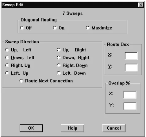
[image:41.612.100.338.135.358.2]33 Figure 3 The Sweep Edit dialog box
Diagonal Routing
Enable or disable diagonal routing. If you select the
Maximize option, Layout uses a 45° angle to route a
connection whenever possible (except if a 90° angle is
necessary to clear pads and obstacles during routing).
Maximize is the default, because routing at 45° angles is
recommended, to minimize the number of segments on the board.
Sweep Direction
During routing, the router travels up and down and across the board using these columns in the direction you specify. For example, if you select the Up, Left option, the router travels up and down the columns from the defined DRC box, working first from the right to the left side of the board. That is, it finishes routing each column before moving to the next column to the left. Each time the router reaches the edge of the board, it returns to the defined DRC box before continuing.
Route Box
You can change the size of the DRC box using this option. Changing the size of the DRC box is usually the only adjustment you have to make in the Sweep Edit dialog box. The default route box size is 250 x 200.
The following values are recommendations:
Overlap X, Y
The Overlap percent determines the amount of space the router uses to reroute tracks as it moves from window to window. It is recommended that you leave these values at the default. If the overlap is too small, you could end up with many small partial routes. If the overlap is too big, the router will tend to try to rip up unneeded routes.
Editing route pass parameters
You can enable and disable sweeps and sweep passes using the Route Pass spreadsheet. You can also access and
20 mils or 25 mils grid 5 mils, 81/3 mils, or 10
mils grid Default 250 x 200 250 x 200
Maximum 300 x 250 350 x 300
Editing strategy files
35 Note
There is usually no benefit in running multiple passes per sweep.
The three passes per sweep listed in the Route Pass spreadsheet are
there as alternatives and are intended to be run one pass per
sweep.
To edit route pass information
1 Choose the spreadsheet toolbar button, choose
Strategy, then choose Route Pass. The Route Pass spreadsheet displays.
2 Double-click in a cell in the Route Pass spreadsheet.
The Edit Route Pass dialog box displays.
3 Select the Enabled option to enable the pass for
[image:43.612.101.270.332.586.2]autorouting.
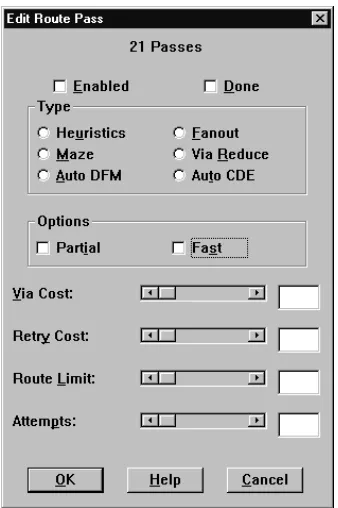
Figure 4 The Edit Route Pass dialog box
Enabled
Done
The Done checkbox is selected after the autorouter has completed the pass you’re editing.
Type
Select the type of pass that you want the autorouter to perform.
Heuristics. Sweeps through the design in an attempt to
route connections using simple wire patterns defined by the router.
Fanout. Routes most SMT pads to through vias. The router
uses a simple pattern search to locate legal locations inside, and then outside, the IC. In some cases, especially on a doubled-sided SMT board, neither path is clear. In that case, the router will drop the connection and go on to the next one. You can ignore failures during this sweep, because the router will connect them later. This option is not recommended.
Maze. Sweeps through the design attempting different
paths to make connections.
Via Reduce. Use the VIARED_H or VIARED_V strategies
to run via reduction on the fully routed board. In most cases, Via Reduce is unnecessary, since the router minimizes vias as it progresses through the routing operation.
Auto DFM (Automatically Design for Manufacturer).
Attempts to straighten tracks and clean up the board. You usually do not need to run Auto DFM, because the router straightens and cleans up the board on its own.
Auto CDE (Automatically Clear Design Errors). Attempts to
remove incomplete tracks from the board so that the design is clean for rerouting.
Editing strategy files
37
Options
The Partial option allows tracks to be partially routed during a sweep if the track extends beyond the active routing window. The Fast option is recommended for a quick routing or place check; it is not recommended for production board routing.
Via Cost
Indicates how conservatively or freely the router will use vias to make connections. In other words, via cost is calculated as the approximate distance that the router travels in the perpendicular direction (the non-standard direction, horizontal or vertical, for the layer) before choosing to use a via. The default Via Costs are 70 for two- and four-layer, through-hole boards, and 40 for almost all other multilayer and SMT boards.
Retry Cost
Represents the approximate number of times the router tries to shove tracks aside before it rips up the track or routes through the track. Using values of 30 or 60, the router is not likely to rip up the track, unless the board cannot be easily routed using shove. If the router rips up a track or routes through a track, it returns to the track to find a new path for it and completes the connection.
Route Limit
Controls the amount of effort the router will use to route a given track. That is, the higher the route limit, the harder the router will try to make a connection, regardless of how long or winding the track becomes. A Route Limit of 75 or 80 is the recommended value for route limit.
Attempts
Specifies the number of tries that the router makes on each connection in the current routing window. Attempts should be set within the range of 2 to 25, depending on whether you want the router to route 100% of the connections or not.
An Attempts setting of 25 routes to 100% (or very close). A setting of 10 routes 98% of most boards, a setting of 5 routes 95% of most boards, and a setting of 2 routes 90% of most boards. On the other hand, a low number of attempts routes the board more quickly.
Editing route layer parameters
You set general routing criteria, such as layer cost, primary direction, and between pins cost, by editing the data in the Route Layer spreadsheet.
To edit route layer information
1 Choose the spreadsheet toolbar button, choose
Strategy, then choose Route Layer. The Route Layer spreadsheet displays.
2 Double-click in a cell in the Route Layer spreadsheet.
The Edit Layer Strategy dialog box displays.
3 Set the parameters for Layer Cost, Primary Direction,
Editing strategy files
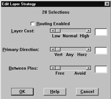
[image:47.612.100.289.136.305.2]39 Figure 5 The Edit Layer Strategy dialog box
Layer Cost
Determines how expensive it is to route on a given layer. For example, for an SMT design, you may want to avoid the outer layers because that is where the pins are located. Layer Cost should generally be set within the range of 40 to 60, except for some special cases. For example, if you want to avoid routing on a particular layer, except when needed, set the overall cost of that layer to 90.
Primary Direction
Primary Direction is not set on a scale from 0 to 100. Vertical layers are assigned a value between 0 and 49, and horizontal layers are assigned a value between 51 and 100. The closer the value is to 50, the more freedom the router has to route in any direction on a given layer. The closer the value is to 0, the more strictly vertical the layer. The closer the value is to 100, the more strictly horizontal the layer. For most boards, 80 and 20 (for horizontal and vertical layers, respectively) will suffice.
For the Next sweep, move the values towards 49 (vertical) and 51 (horizontal), in order to give the router the
maximum amount of freedom, while still giving the router guidance as to which layer goes in which direction.
Between Pins
Gives the router the best possible path selection, and saves the channels between IC pins for short tracks. That is, the higher the Between Pins option is set, the less likely tracks are to be routed between pins.
Editing route spacing parameters
You set general spacing, such as track to track, track to via, track to pad, via to via, via to pad, and pad to pad, by editing the data in the Route Spacing spreadsheet.
To edit route spacing information
1 Choose the spreadsheet toolbar button, choose
Strategy, then choose Route Spacing. The Route Spacing spreadsheet displays.
2 Double-click in a cell in the Route Spacing
Editing strategy files
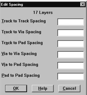
[image:49.612.101.253.135.301.2]41 Figure 6 The Edit Spacing dialog box
Track to Track Spacing
Track-to-track spacing specifies the minimum space required between tracks of different nets, and between tracks and obstacles of different nets. Note that the generic track-to-track spacing set here can be overridden on a “per-net” basis using the Net Spacing By Layer dialog box, which is accessed from the Edit Net dialog box, from within the Nets spreadsheet.
Track to Via Spacing
Track-to-via (and obstacle-to-via) spacing specifies the minimum space required between vias and tracks of different nets.
Track to Pad Spacing
Track-to-pad (and obstacle-to-pad) spacing specifies the minimum space required between pads and tracks of different nets.
Via to Via Spacing
Via to Pad Spacing
Via-to-pad spacing can be used to specify the minimum space required between pads and vias of the same net (as well as different nets, which is the usual case). For example, if you wish to keep a distance of 25 mils between your SMT pads and the fanout vias that are connected to the pads, set Via to Pad Spacing to 25.
Pad to Pad Spacing
Index
A
Attempts, 38
auto path route mode, 17
allow off-grid routing, 17 maximize 135 corners, 17
shove components, 17 Autoroute command, 20
autorouting, 19
connecting nets to plane layers for boards with through-holes, 8 SMT boards, 10
gridded, 1 gridless, 1, 3
layer parameters, 38 passes, 34
pre-routing critical nets, 18 single-sided boards, 23
spacing parameters, 40 sweeps, 19, 31
B
Between Pins, 40
Board command, 10–11, 14, 20
C
commands Autoroute, 20
Board, 10–11, 14, 20 Component, 10
Convert to Components, 24, 26 Copy, 23
Create Reports, 21 Design Rule Check, 11, 21
DRC/Route Box, 10 EnableDisable, 19
Fanout, 10–11, 14 Fanout Settings, 11, 14
Jumper, 24, 26
Jumper Settings, 24, 26
Load, 7, 24 Lock, 18, 25
Properties, 20–21, 23 Route Settings, 16–17
Test Point Settings, 21 Component command, 10
connecting nets to plane layers, 8 Convert to Components command, 24, 26
Copy command, 23
creating jumpers for single-sided boards, 26 critical nets, pre-routing, 18
D
Design Rule Check command, 11, 21 disabling nets for routing, 19
DRC/Route Box command, 10 DRC/Route Box, resizing, 34
E
editing
route layer information, 38
route pass information, 34 route spacing information, 40
route sweep information, 31 EnableDisable command, 19
F
fanout, 14 full board, 14
power and ground, 11 Fanout command, 10–11, 14
Fanout Settings command, 11, 14
G
gridded autorouting, 1
interactive routing tools, 3 shove technology, 2
sweep technology, 2 gridless autorouting, 1, 3
SmartRoute, 3 ground
connecting to plane layer, 8 fanout, 11
verifying connection to plane layer, 9
I
interactive routing, 15
interactive routing tools
J
Jumper command, 24, 26
jumper layer, 23
Jumper Settings command, 24, 26
jumpers, 23
jumpers, creating for single-sided boards, 26
L
Layer Cost, 39
layers, parameters for autorouting, 38
library manager, 23 Load command, 7, 24
loading, routing strategy file, 7 Lock command, 18, 25
N
nets
connecting to plane layers, 8
disabling, 19
pre-routing critical, 18
verifying connection to plane layer, 9
P
passes, in autorouting, 34
plane layers
connecting nets, 8
verifying connection of nets, 9 power
connecting to plane layer, 8 fanout, 11
verifying connection to plane layer, 9 pre-routing critical nets, 18
Primary Direction, 40
Properties command, 20–21, 23
R
resizing, DRC/Route Box, 34 Retry Cost, 37
Route Layer spreadsheet, 30
Index
45 Route Sweep spreadsheet, 30
routing
auto path route, 15 interactive, 15
shove track, 15
shoving tracks interactively, 15, 17
routing modes
auto path route mode, 17
interactive, 3 shove track mode, 16
S
shove technology, defined, 2 shove track mode, 16
high power, 16 low power, 16
medium power, 16
shoving tracks interactively, 15, 17
single-sided boards, 23 SMT boards
performing fanout, 10 preparing for routing, 10
spacing, parameters for autorouting, 40 spreadsheets
Route Layer, 30 Route Pass, 30
Route Spacing, 30 Route Sweep, 30
strategy files, loading, 7 sweep technology, defined, 2
sweeps
autorouting, 19
editing, 31 Maze Route, 31
Next, 31
Preliminary Route, 31
Special Options, 31 Win/Comp, 31
T
technology templates, 23 Test Point Settings command, 21
test points, generating automatically, 20 thermal reliefs, 8
through-holes
connecting nets to plane layers, 8
preparing boards for routing, 8
V