Casting Pressure in Two Types of Titanium Casting Equipment
Kouichi Watanabe
1and Toru Okabe
2;*1Division of Dental Biomaterials Science, Department of Oral Health Science, Graduate School of Medical and Dental Science, Niigata University, Niigata 951-8514, Japan
2
Department of Biomaterials Science, Baylor College of Dentistry, Texas A&M University System Health Science Center, 3302 Gaston Ave., Dallas, Texas, 75246 USA
This study theoretically examined the relationship between mold permeability and the casting pressure acting on the molten titanium in two types of pressure casting equipment [two-chamber and one-chamber] for preparing titanium dental castings in order to select the most effective investment material and optimal casting conditions. The casting pressure exerted on the melt can be defined as the pressure difference between the melting chamber and the mold cavity after the molten titanium drops and seals the entrance to the cavity sprue. Differential equations describing the pressure in the mold cavity were derived from the equation of the state of gas as a function of time. Analysis revealed that mold permeability and the operation of each casting unit affect how the casting pressure acts on the melt: a low-permeability mold is appropriate for the one-chamber type but intermediate permeability molds are desirable for the two-chamber type. Using the results of this study and published permeability data on investments, an optimum investment material can be selected for each type of equipment.
(Received July 14, 2003; Accepted September 17, 2003)
Keywords: titanium, casting equipment, casting pressure, castability, permeability
1. Introduction
Titanium has been increasingly chosen for prosthetic applications because of a growing number of allergic reactions to dental casting alloys.1) Although titanium is inherently difficult to cast using the lost-wax method, worldwide efforts at overcoming the technical problems associated with titanium have made it possible to prepare acceptable clinical dental prostheses.2) One of the most
notable developments is the evolution of various types of casting equipment specifically made for making dental appliances. This equipment can be divided into two classes, based on the way in which the casting pressure is generated: one of them utilizes gas pressure while the other uses centrifugal force.
The present article discusses the casting pressure in pressure casting equipment that is constructed with either two chambers or one chamber. The first one will be referred to as ‘‘two-chamber’’ casting equipment, and the second one as ‘‘one-chamber’’ casting equipment. In both types of equipment, inadequate mold filling and intolerable porosity are sometimes observed in titanium castings.3,4)One reason for these poor results is that there are not enough basic data about the casting process itself, and therefore, dental technicians are unable to choose the most appropriate casting conditions, including the selection of an optimal investment material.
Dental castings made from either conventional metals or titanium are generally cast in thin cross sections in a very short time. When the melt (molten titanium) is forced into the cavity of a mold kept at a much lower temperature than the melt (which is the case for most dental casting), rapid cooling and the resultant rapid solidification occur due to the large temperature difference between the mold and the melt. Therefore, applying appropriate power to the melt within a short time (less than one second) is critical for obtaining
sound castings. In spite of the importance of this subject, no one has yet rigorously analyzed the exact casting pressure created in a dental titanium casting unit. For example, the pressure difference between the upper and the lower chambers in a two-chamber unit is often considered to equal the casting pressure exerted on the melt. However, the true casting pressure is believed to be the pressure difference between the upper chamber and the mold cavity.5) In addition, the pressure in the mold cavity changes with time during the casting process.6) In the case of one-chamber
casting equipment, the pressure in the chamber increases quickly with the introduction of argon gas. However, the casting pressure is not the pressure of the introduced gas itself but is the pressure difference between the chamber and ‘‘the mold cavity.’’6)
Other factors to consider are the permeability of the burned-out mold and the influence of the migration of gas through the mold. Several investigators pointed out the importance of selecting an investment material with desirable permeability.7–10) A few research groups determined the permeability values of some burned-out investments as a material constant.11,12)However, no analysis has been done that uses this type of information to evaluate the casting pressure based on the pressure change in the mold cavity.
The purpose of this study was to theoretically evaluate the casting pressure acting on the melt based on an investigation of the pressure changes in the mold chamber both in a two-chamber and a one-two-chamber pressure casting unit and to use the results to identify the optimal investment material for each type of casting equipment.
2. Methods and Results
The theoretical analysis developed in this paper is based on two principles. The first is that the performance of a pressure casting machine is determined by the pressure difference exerted on the melt, which can be called ‘‘casting pressure.’’ The second principle is that pressure difference essentially
*Corresponding author, E-mail: [email protected]
depends on the pressure in the mold cavity, which changes during casting because of the migration of the gas.
Before continuing, it is necessary to explain why the term ‘‘casting pressure’’ is being used in this study instead of ‘‘casting force.’’ The values shown on the gauges of the equipment are only the pressure values in each chamber. To derive the velocity of the metal flow from the equation of motion, one possible way is to estimate each ‘‘internal’’ force exerted on a fluid segment (a small part of the melt) based on Newton’s third law and to treat it as a many-body problem originating from Newton’s second law. As a result, it seems we could calculate the velocity of the small segment of the melt. However, this approach is not possible because the exact force acting on each small segment cannot be estimated. Instead of directly solving Newton’s equation of motion, the flow velocity can be evaluated by using the energy conservation law, where no force is required. In other words, the exact force applied to the melt may still be unknown even though the velocity can be estimated. There-fore, using the term ‘‘casting force’’ is not appropriate for analyzing the mechanics of the pressure casting equipment.
The Bernoulli equation is an energy conservation law13)
that can be applied to the action of the molten metal dropping into the mold through the opening of the mold duplicated from the sprue former (hereinafter, this portion of the cavity will be referred to as the ‘‘sprue former cavity’’) and through the sprue. Thus,
v12=2þgh1þP1=¼v22=2þgh2þP2= ð1Þ
wherev,P,hare velocity, pressure, and height, respectively. The subscript numbers ‘‘1’’ and ‘‘2’’ indicate the locations of the ‘‘top surface’’ and ‘‘bottom surface,’’ respectively, of the melt in the sprue former cavity. In our study, the bottom of the melt is equivalent to the entrance of the sprue. The density of the melt,, is constant. According to the continuity theory,
v1A1¼v2A2 ð2Þ
whereA1is the area on the top of the melt andA2is the
cross-sectional area of the sprue. Typical diameters of the melt surface in the crucible former and of the sprue are 30 and 3 mm, respectively. Thus, the ratio of the areas at these two locations is one hundred. Accordingly, the velocity of v1 is
negligible compared tov2. Therefore, eq. (1) can be rewritten
as follows:
v22=2¼gðh1h2Þ þ ðP1P2Þ= ð3Þ
Since the height difference, (h1h2), is usually a few
centimeters, the geometrical term, gðh1h2Þ, is negligible
compared to the pressure term,ðP1P2Þ=. Thus, the final
equation is derived as follows:
v2 ¼ f2ðP1P2Þ=g1=2 ð4Þ
Namely, the melt velocity in the sprue is proportional to the square root of the pressure difference. This relationship means that the pressure difference is the essential factor to evaluate the performance of pressure casting equipment, as described in Ref. 5.
The casting pressure depends on the pressure in the mold cavity, which changes with time because of the diffusion of
the argon gas with time. The amount of diffusion depends on several factors, for example, the pressure difference between the chamber and the cavity. This phenomenon is a typical example of Fick’s first law.14)
An estimate of the pressure change in the mold cavity should begin with the equation of state,15) which can be
applied to a thermodynamic system bounded by an arbitrary surface:
P¼nRT=V ð5Þ
wherePis the pressure of the gas,nis the mole number of the gas,Ris the gas constant,T is the absolute temperature, and V is the volume in this system. In this study, P is argon pressure,nis the mole number of argon, andVis the volume of the mold cavity.
Using eq. (5), an infinitesimal pressure change in the mold cavity,dPðtÞ, during an infinitesimal interval,dt, is expressed with the following equation:
dPðtÞ ¼ fðRT=VÞ@n=@tgdtþ ðnRT=VÞ
fð1=TÞ@T=@t ð1=VÞ@V=@tgdt ð6Þ
The first, second, and third terms in the above equation represent the change of the amount, the temperature and the volume of gas, respectively. The value ð1=TÞ@T=@t in the second term is small compared to the first term because the average gas temperature in the cavity doesn’t suddenly change. We believe that this assumption is reasonable in the early stage of filling by the melt since the thermal conductivity of argon gas (0.18 mW/MK, at 27C)16) is small compared to that of titanium (220 mW/MK, at 27C).17)Our assumption is also reasonable if we consider
the fact that the entire filling process is completed within about 0.5 sec.18)However, in the later stage of casting, some
modification must be made to take into consideration the temperature changes of the argon gas. The third term,
ðnRT=VÞð1=VÞ@V=@t, can be ignored at the first approxima-tion because the rate of volume change is minimal compared to the change of the amount of gas, and the factor of volume change is implicitly included in the first term. Thus, the most significant term acting on the pressure changes in the cavity is the term concerning the migration of the gas, as follows.
dPðtÞ ¼ fðRT=VÞ@n=@tgdt ð7Þ
Since the mechanism for generating pressure difference is quite different in the two-chamber and one-chamber casting equipment, we will present our analysis of the casting pressure for the two types separately.
2.1 Two-chamber casting equipment
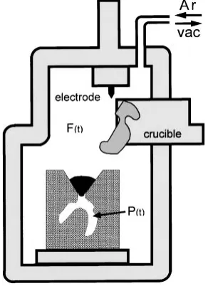
The prototype of a two-chamber casting unit is the Cyclarc (Morita, Japan). It consists of an upper and a lower chamber, with the casting mold in between (Fig. 1). Figure 1 illustrates one moment in the entire casting process when the arc-melted titanium has just dropped into the entrance of the sprue, which is connected to the mold cavity.
changes in pressure occur. At step I, both chambers are evacuated simultaneously to 1.4 kPa. At step II, argon gas (230 kPa) is introduced into the upper chamber. At the same time, the argon arc starts to melt the titanium ingot in the copper crucible in the upper chamber. The pressure in the upper chamber increases to about 200 kPa while the lower chamber is kept at a low pressure (about 20 kPa). At this time, the pressure in the mold cavity is the same as that in the upper chamber because the aperture to the cavity (the sprue) is open to the upper chamber. At step III, the melt drops to the sprue entrance and completely seals off the mold cavity from the upper chamber. The pressure thus increases in the upper chamber and decreases in the lower chamber. At step IV, the pressure in the mold cavity starts to drop since the argon in
the cavity diffuses into the lower chamber through the mold. The pressure on the bottom surface of the melt thus decreases although the pressure on the upper surface of the melt remains constant. This pressure difference generated when the melt flows into the cavity constitutes the casting pressure in this type of casting equipment.
Taking the above sequence of events into consideration, the pressure change can be expressed based on the flow rate formula14)as follows, since@n=@tin eq. (7) means the amount
of gas moving through a porous medium under different levels of pressure:
dPðtÞ ¼ ðRT=VÞðk0S=tdÞfPðtÞ PLgdt: ð8Þ
wherePL is the pressure of the lower chamber,Sis the net
area of the cavity, andk0is the investment permeability. The
net area, S, of the mold cavity at the start of casting is equivalent to the surface of the wax pattern. Term td, the
average thickness of the mold around the cavity, is the average distance from the surface of the mold cavity to the cylindrical surface of the mold. This dimension depends on both the size of the casting ring and the invested position of the pattern. NeitherSnorV(cavity volume) is a constant but they decrease individually with time during the filling process. However, for mathematical simplicity, the ratio S=Vcan be assumed to be constant. Whilek0depends on the
temperature and, thus, on the time during the casting process, there is little change in a short period of time because the investment is a poor heat conductor. At this stage, a new constant, the mold factor,k, is introduced ask¼k0SRT=Vtd.
This constant is considered to be a parameter of the time-dependent casting pressure and is composed of the perme-ability factor (k0S=td), volume of the cavity (V), and the
temperature factor, RT. Thus, eq. (8) can be simplified as follows:
dPðtÞ ¼ kfPðtÞ PLgdt ð9Þ
The solution of eq. (9) is expressed as eq. (10), which indicates the pressure changes in the mold:
PðtÞ ¼PLþ ðPUPLÞekt ð10Þ
where the starting time is defined as the moment when the melt reaches the sprue entrance of the mold, and thenPð0Þis equal to PU. Therefore, the casting pressure, which is the
pressure difference calculated asPUPðtÞ, is expressed as
follows:
PUPðtÞ ¼ ðPUPLÞð1ektÞ ð11Þ
Although the casting pressure is initially zero, it increases with time and finally approaches a constant, (PUPL). Note
that the (PUPL) depends on the mold permeability, as
explained in the next paragraph.
The ultimate value, (PUPL), itself is dependent on the
mold permeability since some argon migrates from the upper chamber to the lower chamber through the mold. In an earlier study,20)the values of (PUPL) were measured (220 kPa for
k¼1and 140 kPa fork¼30) with the pressure gauge of the equipment. Using these data, other values were estimated as follows by means of interpolation or extrapolation; the values of (PUPL) are 220 kPa, 190 kPa, 160 kPa, 140 kPa, and
120 kPa fork¼1, 3, 10, 30, and 100, respectively.
Fig. 1 Two-chamber casting unit shown at the moment the melt drops into the mold;PU: pressure in upper chamber;PL: pressure in lower chamber, P(t): pressure in mold cavity.
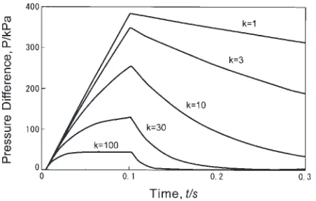
[image:3.595.84.255.68.285.2] [image:3.595.68.270.339.542.2]In Fig. 3, the relationship between pressure difference and time is depicted for variouskvalues [1 (low permeability), 3, 10, 30, and 100 (high permeability)]. These k values were chosen since the published permeability values measured for various presently available investments11) fall into these
ranges. The time range up to 0.3 second was chosen based on previous experimental data,18) where the time needed to
completely fill the mold cavity of a simple plate pattern was within 0.2 second. A complicated cavity, such as a partial denture framework, probably needs two or three times longer to be completely filled.
2.2 One-chamber casting equipment
The prototype of the one-chamber casting equipment is the Autocast (GC, Japan). Unlike the two-chamber casting equipment, the melting crucible and mold are housed in a single chamber (Fig. 4). The way in which the pressure changes with time in each operational step is shown schematically in Fig. 5. At step 1, the chamber is evacuated to 1 kPa. Low-pressure (10 kPa) argon is then introduced at step II, and the argon-arc mechanism starts to melt the
titanium ingot in the copper crucible. The molten metal drops (step III) into the mold as the copper crucible is tilted. As soon as the melt reaches the entrance of the sprue (Fig. 4), high-pressure (400 kPa) argon is introduced into the chamber. As a result, the pressure of the chamber, FðtÞ, increases quickly at step IV and maintains the maximum value (Fig. 5). When the argon is introduced, the pressure increases not only in the chamber but also in the mold cavity. The increase in the mold cavity occurs because some of the argon moves from the chamber to the inside of the mold through its porous media (note that the direction of gas migration is opposite in the two types of casting equipment).
The underlying principle for the basic equation describing the one-chamber equipment is similar to that for the two-chamber type. The infinitesimal pressure change in the mold cavity,dPðtÞ, during an infinitesimal interval,dt, is expressed in the following equation, which corresponds to eq. (9) for the two-chamber type:
dPðtÞ ¼kfFðtÞ PðtÞgdt ð12Þ
where k represents the mold factor, as defined above. Equation (12) can be solved by means of the ‘‘variation of constants’’ technique.21)The general solution is thus given
by:
PðtÞ ¼
Z
kFðtÞektdt
ekt ð13Þ
Note that the initial pressure (10 kPa) in the mold cavity can be ignored in this solution, since the initial pressure acts in both the cavity and the chamber. As a result, the value is canceled when we think of the pressure difference. The integration (eq. 13) can be carried out ifFðtÞ is given as a simple function. Taking into consideration the measured values of the pressure changes with time in the chamber,6)we
assume that the pressure of the chamber initially increases linearly, as shown in step IV with coefficient A (the
Fig. 3 Relationship between pressure difference and time of two-chamber unit.
Fig. 4 One-chamber casting unit shown at the moment the melt drops into the mold; F(t) and P(t) indicate pressure in the chamber and in the cavity, respectively.
[image:4.595.321.530.68.278.2] [image:4.595.57.283.69.217.2] [image:4.595.96.242.548.749.2]instrumental constant) untilt1, the time when the introduced
argon gas reaches a pressure equilibrium in the chamber space outside of the mold; afterwards, it becomes a constant value, At1. Accordingly, the pressure rise in the chamber is
expressed as follows:
FðtÞ ¼At ð0tt1Þ ð14aÞ
FðtÞ ¼At1¼constant ðt1tÞ ð14bÞ
Inserting eqs. (14a) and (14b) into eq. (13), we now have a set of general solutions for the pressure changes in the mold cavity:22)
PðtÞ ¼ ðA=kÞðkt1þektÞ ð0tt1Þ ð15aÞ
PðtÞ ¼ ðA=kÞðkt1þektekðt1tÞ ðt1tÞ ð15bÞ
Thus, the pressure differences between the chamber and the mold cavity can be expressed by the following set of equations:
FðtÞ PðtÞ ¼ ðA=kÞð1ektÞ ð0tt1Þ ð16aÞ
FðtÞ PðtÞ ¼ ðA=kÞðekt11Þekt ðt
1tÞ ð16bÞ
The casting pressure approaches the maximum value at t1
(16a) and then decreases exponentially (16b). Note that in eq. (16), the coefficient (A=k) drastically changes depending on thekvalue.
The changes in pressure difference with time are plotted in Fig. 6 according to eq. (16). In the same manner as for the two-chamber type, results are shown fork¼1(low perme-ability) through 100 (high permeperme-ability). To make Fig. 6, the previous experimental data,6)A¼2000kPa/s andt1¼0:2s,
were employed.
3. Discussion
3.1 Mold factor,k
In the above mathematical development, we introduced the mold factor,k, in the basic differential eqs. (9) and (12). This constant is defined as k¼k0SRT=Vtd, which is the specific
value for each mold at temperature T. We will present the evaluation of thekvalue from the known data and show its validity.
Togaya et al.9) obtained permeability data for various commercial investments by measuring the volume of argon flowing through a disk-shaped investment specimen. They defined the investment permeability,kT, as follows:
kT¼(volume fraction)(thickness)
(pressure difference)(section area)(time) ð17Þ
The amount of gas flow was measured as the volume fraction of gas passing through the investment disk speci-mens in a unit of time under atmospheric pressure (101 kPa) at room temperature. The volume fraction in this formula implicitly contains the pressure factor because the amount of gas is expressed as the product of pressure and volume. Moreover, this factor is equivalent to nRT because the equation of state isPV ¼nRT. That is, the factor,RT, was included implicitly in their result, ‘‘kT’’. The pressure
difference was measured in units of cmH2O. To unify the
unit, we must multiplykTby a factor of 1033, since 1 atm =
1033 cmH2O. In addition, to convert the time from minute to
second, we must dividekTby 60. Nowk0, which is obtained
by multiplying kT by 17.2, represents a general constant of
investment permeability and is more widely applicable because this constant is independent of the pressure unit. Therefore, the mold factor can be estimated based on the experimental valuekT and geometrical factor,S=Vtd.
k¼kT17:2S=Vtd ð18Þ
Typical (S=V) values estimated by Ida23) are 1.3 (crown
and bridge), 2.5 (simple crown), and 5 (total denture plate). Considering these values and the average wall thickness, we adopted 2 as the geometrical factor (S=Vtd). ThekT values
estimated by Togayaet al.11)are 0.03 (Selevest CB; Selec), 0.22 (Titavest CB; Morita), and 3 (Titanmold; Ohara). Using eq. (18), the kvalues now become approximately 1, 8, and 100, respectively, for the above corresponding investment materials. Therefore, Figs. 3 and 6 demonstrate the casting pressure when the k value is between 1 and 100.
3.2 Two-chamber casting equipment
Figure 3 indicates that all the pressure difference curves are equal to zero at t¼0 and increase exponentially with time. With increasing permeability, the pressure difference reaches the final value more quickly, and therefore, a low-permeability mold, such ask¼1, should not be used for this type of two-chamber equipment. However, a high-perme-ability mold (k¼100 in the present analysis) is also unsuitable since the maximum level (120 kPa) is relatively low. Therefore, considering that the actual filling time is 0.2 second, a mold with moderately permeable investment is recommended (for example,k¼30) for this equipment. The experimental data by Togaya et al.11) showed that the
investment recommended by the manufacturer (Titavest CB, Morita, Japan) had intermediate (moderate) permeability (kT¼0:3; this corresponds tok¼10). Our analysis suggests
that an investment with this level of permeability would make an appropriate mold for optimal casting from the standpoint of casting pressure.
Syverud and Her7)estimated mold permeability based on
the pressure differences between the upper and lower chambers and investigated the relationship between cast-ability and permecast-ability. For this purpose, they used custom-built equipment, where the pressure of each chamber could be set up independently. The pressure combinations used for the upper and lower chambers were 53 kPa and 0.1 kPa for
[image:5.595.57.283.71.215.2]the low-permeability mold and 79 kPa and 20 kPa for the high-permeability mold. The pressure differences (PUPL)
were nearly equal under each condition, and therefore, the casting pressure depended on only the exponential factor in the eq. (11). They reported7) that complete castings were
made with a high-permeability mold but not with the low-permeability mold. Their results agree with our present analysis, because the casting pressure of a low-permeability mold is small, as shown in Fig. 3 (for example,k¼1).
3.3 One-chamber casting equipment
In the one-chamber casting equipment, the pressure difference, as well as the mold permeability, changes drastically with time (Fig. 6). Each pressure difference curve has the maximum value at time 0.1 s after initiating the operation; this time is the critical point for the pressure changes in the chamber because a large amount of argon is introduced and the pressure increases according to eqs. (14a) and (14b). After that, the pressure difference decreases because the cavity pressure increases due to the inflow of argon from the outside of the mold. Equations (16a) and (16b) indicate that the time-independent coefficient is inversely proportional to thekvalues. Results of our earlier study24)were consistent with this finding. We examined the
relationship between mold permeability vs. various types of defects in castings made in mesh patterns. When a mold with high permeability (T-invest, GC, Japan:kT¼1,k¼30) was
used, incomplete castings were made, whereas sound cast-ings with no defects were obtained when a low-permeability mold was used (Selevest CB, Selec, Japan: kT ¼0:03,
k¼1). Therefore, note that when a mold with high permeability is used, large casting pressure cannot be attained; an incomplete casting is the result, particularly for complicated geometry. In other words, the casting pressure in the one-chamber type is more clearly influenced by mold permeability than it is in the two-chamber unit.
Moreover, when using investment with high permeability, special techniques are necessary for obtaining a sound casting, such as using a large mold for the casting. Researchers in two studies have carried out mold filling experiments in one-chamber equipment using molds with diameters two to three times larger than the conventional size.8,10)Both of these studies found that castability increased when the larger molds were used. These results also corroborate the present analysis. An important issue here is that the permeability of the mold is inversely proportional to the diameter of the mold, as shown in eq. (18).
4. Conclusions
In this study, we mathematically solved the basic differ-ential equations for the changes in the casting pressure in titanium casting equipment with two chambers and one chamber. Mold factors (the kind of investment material, size of the mold, position of the wax pattern) play a decisive role in developing a desired pressure difference, or casting pressure, for a successful casting. The amount of time to attain maximum pressure difference in the two-chamber equipment is shortened when a high-permeability mold is used. On the other hand, a high maximum pressure difference
can be obtained in the one-chamber casting equipment if a low-permeability mold is used. Therefore, special attention should be paid to factors that influence the mold perme-ability, such as the investment and the size of the mold (casting ring), as well as the position of the wax. By combining analytical results and permeability data, we should be able to match the mold with the type of casting equipment for optimal operation.
Acknowledgments
The authors wish to acknowledge the support for this work from NIH/NIDCR grant DE11787. They are also grateful for editorial assistance with this paper from Mrs. Jeanne Santa Cruz.
Nomenclature
A instrumental constant of a one-chamber casting equipment, Pat1
A1,A2 areas of top and bottom parts of the melt
on the mold crucible, m2
C,C1,C2 integral constants
FðtÞ pressure in the chamber of a one-chamber casting unit, Pa
g gravity constant, mt2
h1,h2 heights of the melt on the mold crucible, m
k mold constant including permeability, mold size, and temperature, t1 k0 investment permeability, m2t1
kT investment permeability reported
by Togaya, m2Pa1t1
n amount of gas in a defined system, mole P pressure of a defined system
at temperature T, Pa
P1,P2 pressures of top and bottom of the melt
on the mold crucible, Pa PL pressure in the lower chamber
of a two-chamber casting unit, Pa PU pressure in the upper chamber of
a two-chamber casting unit, Pa PðtÞ pressure in the cavity, Pa R gas constant, Jmol1K1 S net area of cavity, m2
t time at the initiation of pressure, t td average thickness of the mold around
the cavity, m
t1 time for maximum pressure to be
reached in a one-chamber unit, t v1,v2 melt velocities of top and bottom parts
on the mold crucible, mt1
V total volume of cavity, m3
density of the melt, kgm3
REFERENCES
1) S. Canay, N. Hersek, A. Culha and S. Bilgic: J. Oral. Rehabil.25(1998) 759–764.
3) H. Her, M. Syverud and M. Waarli M: Dent. Mater.9(1993) 15–18. 4) H. S. Al-Mesmar, S. M. Morgano and L. E. Mark: J. Prosthet. Dent.82
(1999) 15–21.
5) K. Watanabe, S. Okawa, O. Miyakawa, S. Nakano, H. Honnma, N. Shiokawa and M. Kobayashi: J. Jpn. Dent. Mater.12(1993) 496–505. 6) S. Okawa, K. Watanabe, M. Kanatani, S. Nakano and O. Miyakawa: J.
Jpn. Dent. Mater.19(2000) 108–114.
7) M. Syverud and H. HerH: Dent. Mater.11(1995) 14–18. 8) Y. Inoue: J. Jpn. Dent. Mater.14(1995) 302–312.
9) I. Watanabe, J. H. Watkins, H. Nakajima, M. Atsuta and T. Okabe: J. Dent. Res.76(1997) 773–779.
10) T. Yoneda and A. Kuroiwa: J. Jpn. Dent. Mater.18(1999) 79–88. 11) T. Togaya, S. Tsutsumi, Y. Tani, Y. Yabugami, H. Hiroshima, S. Iwaki,
S. Ohyagi and S. Shimakawa:Proc., 7th Dental Titanium Conference, Tohoku University, Sendai, Japan; 1994 (Society for Titanium in Dentistry) pp. 11–12.
12) E. Yasuda, A. Kuroiwa, T. Yoneda, A. Ogata, Y. Igarasi, K. Wada and H. Hashimoto: Proc., 7th Dental Titanium Conference, Tohoku University, Sendai, Japan; 1994 (Society for Titanium in Dentistry) pp. 13–14.
13) F. M. White:Fluid Mechanics.2nd ed., (McGraw-Hill, New York, 1986) pp. 147–150.
14) A. G. Guy:Introduction to Materials Science, International Student Edition, (McGraw-Hill Kogakusha, Ltd., Tokyo, 1972) pp. 248–251. 15) P. W. Atkins: Physical Chemistry, 5th ed., (Oxford Univ. Press,
Oxford, 1995) pp. 28–29.
16) D. R. Lide, editor-in-chief:Handbook of Chemistry and Physics, 76th ed., (CRC Press, New York, 1996) section 6, p. 24.
17) D. R. Lide, editor-in-chief:Handbook of Chemistry and Physics, 76th ed., (CRC Press, New York, 1996) section 12, p. 173.
18) K. Watanabe, S. Okawa, O. Miyakawa, S. Nakano, N. Shiokawa and M. Kobayashi: J. Jpn. Dent. Mater.10(1991) 77–96.
19) Operation instruction manual No. 1, Cyclic casting system (for cast titanium frameworks)(J. Morita Co, Kyoto, Japan) pp. 8–9. 20) K. Watanabe, S. Okawa, M. Kanatani, T. Okabe and O. Miyakawa: J.
Jpn. Dent. Mater.18(Spec. Iss.) (1999), 34, #212.
21) A. J. Washington:Basic Technical Mathematics with Calculus, 7th ed., (Addison Wesley Longman Inc., Boston, 1999) pp. 895–896. 22) A. J. Washington:Basic Technical Mathematics with Calculus, 7th ed.,
(Addison Wesley Longman Inc., Boston, 1999) pp. 832–833. 23) K. Ida:Guidebook to Dental Casting (Shika tyuzou no hanashi), 1st ed.,
(Quintessence Co., Tokyo, 1987) pp. 177–180.