Microstructural Refinement of Hyper-Eutectic Al–Si–Fe–Mn Cast
Alloys to Produce a Recyclable Wrought Material
Osamu Umezawa
1;*, Munefumi Nakamoto
1, Yoshiaki Osawa
2, Kenta Suzuki
3and Shinji Kumai
31
Division of Mechanical Engineering and Materials Science, Graduate School of Engineering, Yokohama National University, Yokohama 240-8501, Japan
2National Institute for Materials Science, Tsukuba 305-0047, Japan
3Department of Materials Science and Engineering, Tokyo Institute of Technology, Yokohama 226-8502, Japan
Although the cascade of material flow is presently suitable for the aluminum recycling, a better utilization of secondary alloys is required. In order to establish an upgradeable recycling design for developing wrought products from secondary aluminum alloys, a fine distribution of the primary phases in hyper-eutectic Al–Si–Fe–Mn cast materials has been achieved. Two novel processes were adopted. One was repeated thermomechanical treatment (RTMT), which involves a repetition of a multi-step cold-working followed by heat treatment. The other was rapid solidification by high-speed twin-roll casting to develop a fine solidification structure in a thin sheet. By applying these processes, refined microstructures were successfully obtained. Microstructural refinement by RTMT resulted in the avoidance of early fracture that was detected in the cast material by a tensile test. The RTMT imparted good ductility; therefore, it was possible to allow greater flexibility in the cold working of Al–Si–Fe–Mn cast materials.
(Received June 27, 2005; Accepted August 8, 2005; Published December 15, 2005)
Keywords: aluminum cast alloy, recycle, refinement, thermomechanical treatment, twin-roll casting
1. Introduction
In view of global environmental issues, it has become essential to conserve resources and energy and to reduce environmental pollution, waste and by-products. The recy-cling of aluminum and steel scrap assumes importance, since the production of primary aluminum from bauxite ore consumes a large amount of energy. Moreover, remelting of the aluminum scrap requires only several percent of the energy needed to produce the same weight of the primary aluminum. However, the application of secondary (scrap) alloys has been almost limited to castings. The question arises as to why the cascade of material flow is suitable for aluminum recycling. The products generally consist of many types of materials. Even after a bulk sorting, the elements such as Si, Fe and Mn in secondary aluminum alloys are contaminated. These contaminants are detrimental to lead to very poor formability of wrought products, and their refining is difficult and higher costly. On the other hand, the alloy compositions for casts is simplified by blending aluminum scraps. Spray-forming has been used for refining primary Si crystals in hyper-eutectic Al–Si alloys,1,2)but it is not suitable for mass production. Thus, a new technological model has been developed to make the secondary materials be innoc-uous from the contaminants for their widespread use.
For promoting this model, we have proposed a kind of prototype process for recycling products from aluminum cast alloys,3)and have also examined the statistics of aluminum material flow in Japan. Alloying Si, Fe and Mn, which leads to the formation of primary Si crystal or compound in Al–Si based alloys, provides a good wear resistance, low thermal expansion, and high Young’s modulus and strength at higher temperatures. The Al–Si–Fe–Mn system having multiple phases with low mutual solid solubility is effectively as an in-situ composite. The content ratio of Mn to Fe affects the
morphology of the compound. The hexagonal form of not only the primary Si crystal but also the compound is desirable for the homogeneous distribution after thermomechanical treatment, although Al5SiFe compound exhibits an acicular
form.4)Hence Al–Si–Fe–Mn alloys possess the advantage of recyclable material design. To control balanced properties with ductility and strength, a fine microstructure with multiple phases, mesocomplex structure, is one of the candidates for an alloy design.5) However, the heavy cold working cannot be applied, because it causes severe cracking in the coarse Si crystals and/or compounds.
Therefore, to provide greater flexibility in the cold and/or warm working of Al–Si–Fe–Mn cast materials, a fine distribution of secondary particles in the microstructure has been achieved by employing novel processes such as repeated thermomechanical treatment (RTMT)6) and twin-roll casting.7,8)Microstructural refinement by the addition of elements such as P and Sr into the melt has not been adopted in the present study in order to evaluate the effects of the novel processes on microstructural refinement for hyper-eutectic Al–Si based alloys. The RTMT, which involves a repetition of the multi steps cold-working followed by heat treatment, is a candidate to apply for producing forged parts. A combination of the modified RTMT using a drawing-annealing step and isothermal warm-forging on an Al–Si alloy has already been applied to the manufacture of motorcycle engine pistons.9)The products manufactured by this process have the advantage of requiring considerably less machining and are lighter than the die-cast ones, since they are shaped almost accurately. On the other hand, the strip casting has potential to meet the demand of accommodating more aluminum scrap in the thin sheets such as brazing sheet filler layer.10)Solidification is very rapid in twin-roll casting, leading to a fine and even distribution of secondary particles in the microstructure as well as a marked supersaturation of relatively insoluble elements.
*Corresponding author, E-mail: [email protected]
Special Issue on Growth of Ecomaterials as a Key to Eco-Society II
2. Procedure
2.1 Input and output data of aluminum materials
Input and output data of aluminum materials and products were obtained from the trade statistics reported by the Ministry of Finance, Japan, and the annual report of resources made available by the Research Institute of Economy, Trade and Industry, Japan. Statistics given by Japan Aluminum Association and Japan Aluminum Alloy Refiners Associa-tion, and a document from the Industrial Structure Council, Ministry of Economy, Trade and Industry, was referred. The amount of new scrap was estimated from the project report11) of the Japan Research and Development Center for Metals (JRCM).
2.2 Test materials and microstructural analyses
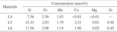
Three types of hyper-eutectic Al–Si–Fe–Mn casts with a diameter of 40 mm were examined by thermomechanical treatment. The casts, L4, L5 and L6, were fabricated by gravity casting with a permanent mold. The chemical compositions (in mass%) of the casts are listed in Table 1. Materials with almost the same compositions and high Si content were examined using the rapid solidification method described in below.
The microstructure was analyzed by using an optical microscope (OM), scanning electron microscope (SEM) equipped with energy dispersive spectroscopy (EDS), differ-ential scanning calorimetry (DSC), and X-ray diffraction (XRD). Both heating and cooling rates in the DSC measure-ment were maintained at 1 K/s in order to detect melting and solidification phases.
2.3 Thermomechanical treatment
When cooling large ingots slowly, the cast materials exhibit extremely low workability at and below room temperature since they involve very large Si crystals and compounds. A hot-working step needs to be introduced to provide a certain cold-workability for the RTMT, such as a 20% reduction without visible cracks.12) The casts were heated at a temperature between 673 and 693 K and were either swaged (L4) or extruded (L5 and L6) with a working strain of 0.97 (¼ln A0=A, A0: section area of sample, A:
section area of worked sample).
Rods with a diameter of 21 mm were annealed at 793 K for 3.6 ks, followed by repeated thermomechanical treatment (RTMT)6)was conducted. Cold swaging was carried out in several steps; intermediate annealing operations were intro-duced at 793 K for 1.8 ks. Each working reduction was approximately 10% in section area, and the working-anneal-ing cycle was repeated seven times. The total reduction in area was approximately 70%.
2.4 Tensile test
Tensile testing was conducted in a motor-driven testing machine at 293 K (in air) under displacement control. The displacement rate for each specimen was chosen to corre-spond to an engineering strain rate of approximately 2104s1within the plastic regime. Specimen elongation was monitored by using a clip gauge with the knife edges set onto the tensile specimen at both ends of the gauge length
(25 mm). Engineering stress and strain data were converted to true stress and true strain values by assuming volume conservation during uniform elongation. The tensile speci-mens were machined from rods parallel to the longitudinal direction.
2.5 Twin-roll casting
By using a vertical-type twin-roll caster,7)a thin cast strip with a thickness of approximately 2 mm was fabricated using four types of hyper-eutectic Al–Si mother alloys such as Al– 20Si (TR3), Al–7Si–2Fe–2Mn (TR4), Al–15Si–2Fe–2Mn– 2Cu (TR5) and Al–18Si–2Fe–2Mn–2Cu (TR6), expressed in mass%. The roll caster was equipped with a pair of water-cooled copper rolls, and no lubricant was applied to the roll surface. The roll diameter was 300 mm, and its face width was 100 mm. A casting nozzle made of a heat-insulating material was mounted on the twin roll. A cooling slope inclined at 45 degrees and composed of a mild steel plate with a length of 400 mm and width of 100 mm was used for low superheat and semisolid casting. The alloy was melted and poured into the nozzle at 998 or 968 K (Table 2) through the cooling slope. The casting temperature was determined with 50 K superheat from the liquidus temperature in each material. The roll speed was 0.5 m/sec. A very small separating force (0.14 kN/mm) was applied in order to prevent the strip from sticking to the roll.
The skin-pass rolling and annealing cycle was introduced in order to stretch the cast strips with a smooth surface. The annealing condition was maintained at 793 K for 3.6 ks.
3. Results and Discussion
3.1 Aluminum material flow analysis
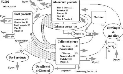
[image:2.595.305.549.85.152.2]Figure 1 summarizes the statistics of the aluminum material flow in Japan for the year 2002. Although the generated aluminum scraps are estimated at approximately 3.5 million ton, the amount of scrap collected from markets and factories (in-house scrap) is 1.5 million ton and 1.6 million ton, respectively. New scrap is estimated at approx-imately 0.4 million ton, and the remaining is old scrap. A large amount of reusable products, parts, scraps and mixed-metals with an estimated 0.3 million ton of aluminum
Table 1 The chemical compositions of test materials in mass pct.
Materials Concentration (mass%)
Si Fe Mn Cu Mg Zr
[image:2.595.305.549.187.261.2]L4 7.56 2.56 1.83 <0:01 <0:01 — L5 15.33 2.03 1.79 2.31 0.01 0.40 L6 17.56 2.08 1.74 1.96 0.02 0.45
Table 2 Twin-roll casting temperature and strip thickness.
Materials Casting temperature (K)
Strip thickness (mm)
Rolled sheet thickness (mm)
TR3 968 2.0 1.5
TR4 998 2.2 1.8
TR5 998 2.2 1.8
TR6 998 2.2 1.8
resources has been exported. Approximately 1.1 million ton of secondary alloys is produced in refineries. The supply of domestic scraps for the secondary alloys satisfies about 50 percent of the demand, and secondary alloys and scraps (0.13 million ton) have been imported from North America etc. The total inputs of secondary alloys and new ingots from abroad are about 1 million ton and 1.8 million ton, respectively. Secondary alloys are in demand mainly for automotive casting parts, except beverage cans. The appli-cation of secondary alloys to wrought products may be advantageous primarily in Al–Si alloys since the cascade of aluminum material flow is still suitable for aluminum recycling due to less or no dilution by raw materials.
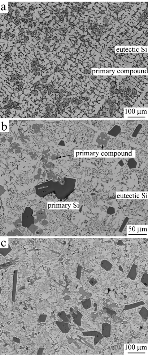
3.2 Microstructure
Figure 2 shows the solidification structure of the test materials. Each cast material contains primary intermetallic compounds and/or coarse primary Si crystals. Both primary compounds (light gray color) and Si (dark gray color) crystals are hexagonal in shape and several ten mm in diameter. Eutectic Si exhibits a needle- or plate-loke form. The EDS analysis results showed that the compound contained the elements Al, Si, Fe, and Mn. The approximate composition of the compound was Al6Si1:5FeMn1:5. Copper was soluble with
less than 0.5 mass% in the compound of both L5 and L6. In the solidification stage of the test materials, the temperature of the eutectic reaction was the same at 843 K, at which a large emission peak was detected in the DSC measurement, as shown in Fig. 3; however, their liquidus temperatures were different. In L4, a large emission peak for -solidification was also observed at 863 K. For the primary compound, a small emission peak corresponding to the liquidus temperature was detected at 948 K. Two other small peaks were detected at 898 K in L5 and 933 K in L6; these are
related to the primary Si crystal. The phase identification of the compound with XAD analysis was not carried out.
The secondary dendrite arm spacing (DAS) of primary aluminum in L4 is about 25mm, as shown in Fig. 2(a). The relationship between the DAS and the cooling rates has been investigated for A356 alloys.7)Based on this relationship, the cooling rate of these permanent mold casts was estimated as several K/s.
3.3 Fragmentation of primary phases
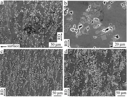
Through the hot and cold workings, the primary Si crystals and compounds were broken into a few pieces with a decrease in size. In L4, the compounds are refined to less than tenmmin diameter near the sample surface only through the hot-swaging operation [Fig. 4(a)]. After RTMT, even in the central part of L4, the compounds are broken into pieces of less than a few tenmmin diameter [Fig. 4(b)]. The eutectic Si is also fragmented. These dispersed crystals are spheroidized. On the other hand, in L5 and L6, which have higher Si content, both primary Si crystals and compounds are refined to less than a few tenmmin diameter, as shown in Figs. 4(c) and 4(d). This remarkable refinement near the sample surface is comparable to that in L4. The eutectic Si crystals are also divided and dispersed as fine particles. Although the Si crystals and compounds are mostly aligned along the longitudinal direction (RD), the second phases are distributed in the matrix with a high density and fine size. They are also partially spheroidized.
3.4 Improvement of ductility
[image:3.595.85.510.76.334.2]markedly increases due to the RTMT. The L4-RTMT sample exhibited the necking instability, but the cast ones fractured before approaching it. Hence, microstructural refinement could result in the avoidance of early fracture that was characteristic of the cast material.
The RTMT materials in both L5 and L6 did not overcome the early fracture since the dispersion of the fragmented primary Si crystals and/or compounds in the aluminum
matrix through the RTMT was possibly insufficient. The solidification structure strongly influences the fragmentation of the primary phases.13)In fact, as compared with conven-tional direct chill casting, in fact, the casts were slowly cooled without modification. The local density of the primary Si crystals and/or compounds was considerably high, and their size in the solidified state was relatively large [Figs. 2(b) and 2(c)].
The yield stress of the RTMT materials is lower than that of the cast ones since the working and annealing operations may result in a decrease in the solute content in the aluminum matrix. This imparts a significantly enhanced ductility for the RTMT materials. Therefore, in L4-RTMT, a heavy plasticity of over 90% reduction in the section area was achieved. This indicates the possibility of designing balanced properties with cold or warm working.
3.5 Microstructural modification with rapid
solidifica-tion
The twin-roll casting was successfully carried out for producing a thin sheet. The resultant thickness of the cast strips is summarized in Table 2, and their chemical compo-sitions are listed in Table 3. The twin-roll cast plate exhibits a fairly refined primary dendrite and eutectic solidified structure, as shown in Fig. 6(a). The DAS of the mid-thickness region is approximately 10mm. This value is less than half that of the permanent mold cast L4. The cooling rate of the cast strips is estimated as several ten K/s.7)This is almost ten times that of the permanent mold cast materials.
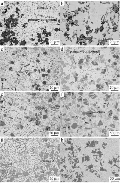
Figure 6 shows the solidification structure and micro-structure of the cast strips after skin-pass cold rolling. Each strip contains primary compounds and/or primary Si crystals. They exhibit a hexagonal form similar to those of the permanent mold casts; however, their size is refined to approximately half that of the cast materials (Fig. 2). Since their liquidus temperatures are much higher than the primary solidification or eutectic temperature, as shown in Fig. 3, the size of both primary Si and compounds depends not only on cooling by twin-roll casting but also on the cooling rate in the cooling slope. Consequently, a higher cooling rate around the liquidus temperature is required to obtain much finer primary phases in the structure. The photographs in Fig. 6 show a mid-thickness region in the transverse (TD) section. The primary compounds and/or primary Si crystals were segregated in this region. These phases were less distributed near the strip surface and therefore they may condense in the liquid phase during-solidification or the eutectic reaction. Fig. 2 Microstructure showing a center part of cast materials in the
transverse section: (a) L4, (b) L5 and (c) L6.
[image:4.595.50.289.71.642.2] [image:4.595.311.541.71.177.2]As shown in Fig. 6(f), cracks were formed in the primary phases with a small amount of cold working, although eutectic Si crystals and smaller particles were finely dispersed and spheroidized. A thermomechanical treatment such as hot working or long-time annealing may be required to improve the ductility of the cast strips.
4. Conclusions
A new design concept for the recyclable Al–Si–Fe–Mn cast materials has been proposed, wherein a combination of multiple phases with fine microstructure is considered in order to achieve balanced properties. The main results are summarized as follows;
(1) Although the cascade of material flow is presently suitable for the aluminum recycling, a better utilization of secondary alloys is required. The application of secondary alloys to wrought products may be advanta-geous in Al–Si alloys firstly.
(2) A novel process, repeated thermomechanical treatment (RTMT), was successful in the achieving microstruc-tural refinement of hyper-eutectic Al–Si–Fe–Mn cast materials. The RTMT brought about the fine dispersion of both Si crystals and compounds, and their spheroid-ization was also achieved.
(3) Microstructural refinement by the RTMT resulted in the avoidance of the early fracture that was characteristic of the cast material in the tensile test. The RTMT imparted Fig. 4 SEM microstructures: (a) one forth depth of hot-worked L4 material in the longitudinal section, (b) a center part of L4 RTMT
material in the transverse section, (c) one forth depth of L5 RTMT material in the longitudinal section, and (d) a center part of L5 RTMT material in the longitudinal section.
50 100 150 200
0 0.05 0.1 0.15 0.2
Engineering strain, ε
293 K L4 RTMT L5 RTMT
L4 AC L5 AC
Engineering stress,
σ
/ MPa
[image:5.595.82.515.72.401.2]Fig. 5 Engineering stress versus engineering strain curves at 293 K for L3 and L4 materials in both as cast and RTMT conditions.
Table 3
Materials Concentration (mass%)
Si Fe Mn Cu Mg
TR3 20.6 0.13 0.01 0.03 0.01
TR4 7.37 2.31 1.99 <0:01 <0:01
TR5 14.92 2.23 2.07 1.94 0.01
[image:5.595.57.283.469.630.2]good ductility and indicated the possibility of designing balanced properties with cold or warm working. (4) Another novel process, twin-roll casting, directly
produced a thin sheet that exhibited a finer solidification structure in the hyper-eutectic Al–Si–(Fe,Mn,Cu) al-loys.
Fig. 6 Microstructure showing a mid-thickness region of cast strips in the transverse (TD) section: (a), (b) TR4, (c), (d) TR5, (e), (f) TR6 and (g), (h) TR3. Photographs (a), (c), (e) and (g) show the strips as cast condition. Photographs (b), (d), (f) and (h) show the rolled sheet after two cycles of rolling-annealing operations. Reference direction (RD) indicates casting or rolling direction. ND stands for normal direction of the strips. Crackings in either primary Si crystal or compound are detected in the rolled sheet materials.
[image:6.595.98.501.70.679.2]Acknowledgement
This work has been supported by RISTEX of Japan Science and Technology Agency. One (O.U.) of the authors would like to thank Mr. T. Suzuki (YNU, now Aisin AW Ltd.), Mr. M. Ohkubo (JAA) and Dr. S. Takamori (NIMS) for their help.
REFERENCES
1) K. Shibue and N. Tokizane: Materia Japan34(1995) 736–740, (in Japanese).
2) N. Tokizane, H. Sano, K. Shibue and Y. Ohkubo: J. Jpn. Soc. Powder Powder Metall.41(1994) 927–932, (in Japanese).
3) O. Umezawa, H. Ohya, T. Yoshioka, S. Kumai and C. Nishimura: Trans. MRS-J29(2004) 1829–1832.
4) C.-Y. Lim, O. Umezawa and K. Nagai: Met. Mater. Inter.4(1998)
1027–1031.
5) O. Umezawa and K. Nagai: Trans. MRS-J20(1996) 190–193. 6) O. Umezawa and K. Nagai: Metall. Mater. Trans. A30A(1999) 2221–
2228.
7) S. Kumai, K. Suzuki, Y. Saito and T. Haga: Trans. MRS-J29(2004) 1817–1822.
8) T. Haga, M. Ikama and S. Kumai: Trans. MRS-J29(2004) 1823–1828. 9) H. Sakurai, Y. Amaki, M. Kunii, T. Oka, N. Miyamoto and M. Nakai: Proc. 18th Inter. Forging Congress, (Jpn. Forging Soc., Tokyo, 2005) pp. 48–66.
10) T. Doko, Y. Yanagawa and S. Tanaka: Furukawa-Sky Review1(2005) 27–32, (in Japanese).
11) R&D on advanced aluminum recycling technologies, (JRCM, Tokyo, 2005).
12) H. Yokoyama, O. Umezawa, K. Nagai and K. Kokubo:Proc. 4th Inter. Conf. ECOMATERIALS, (The Soc. Non-traditional Tech., Tokyo, 1999) pp. 491–494.