In the past they were developed several types of loading and testing devices for measurement of trac-tor engine horsepower (PETRANSKÝ 1989). The first devices were usually hydrodynamic types known as water hydrodynamic brakes. During the test of trac-tor engine trac-torque and speed of the power take off shaft were measured. On the base of the measured values i.e. torque and speed the horsepower of engine was calculated. Nowadays the water hydrodynamic brake is presented as out-dated type which is used only seldom in practice (PETRANSKÝ et al. 2004).
Electric loading device is other type of the engine brake and usually is called as electric dynamometer or eddy current brake according to the used load-ing principle. This type of the engine brake is also programmable to permit various loading regimes of the tested engine.
Growing requirements on functional ability of constructions and their reliability, lower mass, re-duction of negative influence on environment have evoked unprecedented interest in possibilities and methods of laboratory test and also in methods of mathematic modeling of dynamically strained
ma-chines and their parts (PETRANSKÝ in TKÁČ, ŠKULEC 2000). On this occasion there is a question how to transmit the measured and recorded operational process to input of loading system as a controlling signal or how to realize equivalent process by com-puter (TKÁČ et al. 2001b).
In this contribution the results have been obtained in research of loading device for static and dynamic tests of the tractor engines by power take off shaft. At Department of Vehicle and Heat Device, Faculty of Agriculture Engineering, Slovak Agricultural Uni-versity in Nitra we carry out research of hydraulic systems of tractors and other agricultural machines since 1970. For this reason we try to use obtained knowledge and experiences in the area of hydraulics.
MATERIAL AND METHODS
The goal of this contribution was to design test-ing device for measurement of speed and dynamic characteristics of tractor engines by power take off shaft to accelerate development of the tractors. This testing device and dynamic loading methods allow
Supported by the Scientific Grant Agency VEGA, Research project No. 1/0588/03 Reduction of Pollution of Soil and Environ-ment by Agricultural Technique.
Testing device with opened hydrostatic circuit for dynamic
loading of the tractor engine by power take off shaft
Š. DRABANT
1, M. BOLLA
2, A. ŽIKLA
1, I. PETRANSKÝ
1, J. ĎUĎÁK
11
Slovak Agricultural University, Nitra, Slovak Republic
2
Peugeot Citroën Automobiles Slovakia, s. r. o., Trnava, Slovak Republic
ABSTRACT: The developed loading device with opened hydrostatic circuit for measurement of speed and dynamic characteristics of the tractor engine by power take off is presented. This loading device may also be used as a portable type for field measurement. At present for development of these loading devices controlled hydrogenerators and electro-hydraulic proportional pressure valves directed by computer may by used to adjust geometrical volume of the hydrogenerator from zero to maximum value. There is a possibility to built these devices which consist of one hydro-generator and one by-pass valve for the maximum power of internal combustion engine 420 kW which is sufficient from the point of view of practical need. Thus optional loading regime may be used according to the tractor engine horsepower to achieve the required accuracy of measurement.
several times to accelerate development of the trac-tor when the testing device is suitable for this pur-pose (PETRANSKÝ 1989). There are several systems of using of hydraulic loading elements. However we have decided for hydrostatic elements suitable added by measurement, evaluation and control electrical technique (TKÁČ et al. 2000). As is known thus designed testing device has great technical, economical and also environmental advantages (TKÁČ et al. 2001a). For determination of require-ments on testing device essential technical data and parameters of tested tractors loading hydrostatic generators, hydraulic and electro-hydraulic ele-ments, measurement, control and evaluation equip-ment must be known.
Theoretical assumptions for measurement and evaluation of loading torques by
hydrostatic circuits
Static loading during measurement of speed characteristic of engine and also dynamic loading necessary for simulation of dynamic regimes of engine may by realized by two methods. Either by change of pressure of hydrogenerator under constant geometric volume of hydrogenerator or by change of geometric volume hydrogenerator under constant pressure of hydrogenerator.
For the network driving simulater unit the differ-ence between torques is expressed by formula:
dωa
Mka – Mkz = (Ia + Is) × (N×m) (1) dt
where: Mka – torque on the connecting shaft of the network (driving unit- loading device- simulator) (N×m),
Mkz – loading torque (N×m),
Ia – moment of inertia of driving unit (kg×m2),
Is – moment of inertia of simulator unit (kg×m2),
ωa – angular speed of output shaft of driving unit (rad/s),
t – time (s).
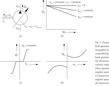
The loading torque Mkz on the output shaft of driving unit (e.g. internal combustion engine-gear box-power take off shaft) will be produced by hy-drostatic circuits of simulator. The basic element of the loading hydraulic circuits will be hydrostatic generator. Characteristics and values describing the hydrogenerator are shown in Fig. 1. The hydrostatic generator may be described by following equations. The flow is expressed by formula:
VG
QG = × ωG – ZG × ∆pG (m3/s) (2) 2π
where: QG – flow of hydrogenerator (m3/s),
VG – geometric volume of hydrogenerator (m3),
ωG – angular speed of hydrogenerator (rad/s),
ZG – penetrability of hydrogenerator (m5/N/s), ∆pG – pressure declination of hydrogenerator (Pa).
The input torque of hydrogenerator will be:
������������� ��
���
������� ��
���
��
���
������������ �����������
������� ������������� ������������
��
�� ��
�����������
���
�� ��
[image:2.595.68.454.458.761.2]�� ��
�
Fig. 1. Characteristics of described hydrogenerator
(a) graphic mark of rotary one-way controlled hydrogenerator and his basic parameters,
(b) characteristics QG = f(∆pG) for various values of penetrability ZG
when geometric volume VG and angular speed ωG are constant, (c) characteristics QG = f(VG) when angular speed is constant, (d) characteristics MkT = f(ωG)
(a) (b)
(c) (d)
constant
constant constant; ωG = constant
constant
VG dωG
MkG = × ∆pG + MkT + IG × (N×m) (3) 2π dt
where: MkG – input torque of hydrogenerator (N×m),
MkT – torque necessary for overcoming passive resistances of hydrogenerator (N×m),
IG – moment of inertia of hydrogenerator (kg×m2).
The torqueMkT necessary for overcoming passive resistances of hydrogenerator is expressively nonlin-ear due to changes of friction of the functional parts in the area of low speed.
The input power on the shaft of hydrogenerator will be calculated by this formula:
VG dωG
PG1= × ∆pG × ωG +MkT × ωG + IG × ωG × (W)(4) dt
After adaptation it will be:
dωG
PG1 = QGt × ∆pG × MkT × ωG + IG × ωG × (W) (5) dt
It is necessary to secure possibility of input pressure change it is change of pressure ∆pG. As originates from the formula 3 torque MkG is possible to be changed by the pressure decline ∆pG when VG = constant or by change of geometric volume VG when ∆pG = constant. The geometric volumeVG = αG × VGmax is possible to be changed in certain range by the adjustment of param-eter αG of which maximum value is αGmax = 1.
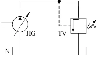
When geometric volume VG = constant pressure decline ∆pG is possible to be changed by pressure valve which is connected to the output of hydrogen-erator (Fig. 2).
Pressure valves present automatic control systems so their controlled value is pressure. Static character-istic of the pressure valve is shown in Fig. 3a where pT1 is pressure and QT1 flow when the valve is entirely opened. Dynamic characteristic of the pressure valve is shown in Fig. 3b.
Proposal of loading regimes
Basic scheme of network for measurement of load-ing regimes of internal combustion engines by power take off shaft is shown in Fig. 4. The proposed loading regimes realized by brake (simulator) are following: – loading by constant torque,
– loading by jumping torque, – loading by sinusoidal torque, – loading by transitional torque, – loading by operational torque.
During simulation of the dynamic regimes of engine and power take off shaft in laboratory con-ditions the required loading course is realized by change of the pressure decline of hydrogenerators or by change of the geometric volume of hydromotors. Loading torque MkVH on the power take off shaft will be realized by the output pressure pG of hydrogen-erator HG when geometric volume VG = αG.VGmax. Loading torque MkVHon the power take off shaft is realized by output pressure of the hydrogenerator HG with given geometric volume VG = αG × VGmax. The loading torqueMkVH and loading pressure pG is realized by hydrostatic circuits of the loading device. The basic hydraulic elements of the loading hydrau-lic circuits are hydrogenerators and valves. There is a need to secure change of output pressure pG it is pressure diference ∆pG to use hydrogenerators in the loading devices.
The loading torqueMkGin the input of hydrogene-rator is possible to be changed by change of pressure pG when VG constant or by change of the geometric volume VG when ∆pG = constant. The geometric vol-ume of controlled hydrogenerators may be changed by change of adjustment αG in the range from zero to one. When hydrogenerator with constant geometric
��
��
���
���
���
���
�
��
��
� �
��
��
�
�� ��
[image:3.595.65.296.59.154.2]�
�
Fig. 2. Hydrostatic scheme of connecting of pressure valve in function as by-pass valve
Fig. 3. Characteristics of pressure valve: (a) static characteristics, (b) dynamic characteristics
(a) (b)
[image:3.595.87.251.486.583.2]volume is used then pressure pG may be changed by pressure valve connected to the output of hydrogen-erator according to scheme shown in Fig. 4.
The pressure valves present automatically con-trolled systems of which pressure is the concon-trolled value. For the hydrostatic circuit shown in Fig. 4 we can write following formula:
αmax × VGmax × ∆pG = 2π × MkZ (N×m) (6)
where: VG – geometric volume of hydrogenerator (m3), ∆pG – pressure declination of hydrogenerator (Pa),
Mkz= MkG – loading torque (N×m),
αG – adjustment of hydrogenerator, for one-way hydrogenerator αG є
<
0.1>
,VGmax – maximum geometric volume of hydrogenera-tor.
From the formula (6) after adaptation we get: αG × VGmax × ∆pG
MkZ = (N×m) (7)
2π
According to the formula (7) the value of torque Mkz may be changed as follows:
– by change of ∆pG when αG = constant then formula (7) after adaptation will be:
Mkz = k1 × ∆pG (N×m) (8) where:
αk G× VGmax
1 = (9)
2π
by change of values αG when ∆pG = constant then formula (7) will be as follows:
Mkz = k2 × αG (N×m) (10) where:
k VGmax× ∆pG
2 = (11)
2π
– by change of values αG and ∆pGat the same time. When loading device consists of two separated loading circuits formed by two hydrogenerators HG1
and HG2 and two by-pass pressure valves TV1 and TV2 the loading by constant torque Mkz1 is realized by pressure decline ∆pG1 when geometric volume VG1 of the hydrogenerator HG1 is constant. In this case the simulation of torque M´kz will be realized by change of geometric volume VG2 of the controlled hydrogenerator HG2 when pressure decline ∆pG2 is constant.
The resultant instantaneous loading torqueMkz on the shaft of loading device is given by formula:
Mkz = Mkz1 + M´kz (N×m) (12) Operational loading is also possible to realize by suitable electro-hydraulic proportional valves. By these valves change of the pressure declination is re-alized when loading hydrogenerators with constant volume are used. The operational loading may be also realized by servo-valves in connection with suitable computer control system when the hydrogenera-tors are suitable for this purposes. In this case the hydrogenerators must be equipped with control of geometric volume by servo-valves and then during simulation the output pressure of the hydrogenera-tors is constant.
IMPLEMENTATION OF RESULTS
Description of the testing device for measurement of speed characteristic and
dynamic loading of tractor engine by power take off shaft
The power take off shaft VH is connected with in-put shaft of the loading hydrogenerator HG without gear box (Fig. 5). In this case speed of the input shaft of hydrogenerator is the same as speed of the power take off shaft. Required change of dynamic loading of the hydrogenerator HG is continuously control-led by the electro-hydraulic proportional pressure valve EHTV. Oil filter F is connected to the input of hydrogenerator.
�
��
��
�� ���
��
���
��
���������
� ��
�
��� ��
���
�������������
[image:4.595.104.486.61.181.2]�
The electro-hydraulic proportional pressure valve EHTV is the active part of electro-hydraulic sys-tem which realizes continual transmission of the controlling signal into the proportional pressure of liquid. The pressure valve TV serves as a safety valve. A suitable numeric controlling system which consists of computer PC and D/A converter is need to originate required loading by electro-hydraulic proportional valve.
When rated speed of the power take off shaft and rated speed of the input shaft of hydrogenerator is unequal gear box must be used. The gear box is placed between the power take off shaft VH and the hydrogenerator HG.
For the scheme (without gear box) shown in Fig. 5 the torque MkVH on the power take off shaft is given by formula:
∆pG × αG × VGmax
MkVH = (N×m) (13)
ηGm × 2π
where: MkVH – torque on power take off shaft (N×m), ∆pG – pressure decline in output of hydrogenerator
(Pa),
αG – adjustment of hydrogenerator,
VGmax – maximum geometric volume of controlled hydrogenerator (m3),
ηGm – mechanical efficiency of hydrogenerator.
Value of the torque MkVH is determined by calcula-tion and for this reason the speed of engine, pressure decline ∆pG and adjustmentαG must be measured. Other values required for the calculation according to the formula (13) are given.
When the gear box between power take off shaft and input shaft of hydrogenerator is used then the torque MkVH will be expressed by formula:
∆pG × αG × VGmax
MkVH = (N×m) (14) iG × ηGm × ηPrGm× 2π
where: iG – gear ratio of gear box,
ηPrGm – efficiency of gear box,
ηGm – mechanical efficiency of hydrogenerator.
Both measurement methods of torque MkVH mentioned above are indirect so called informative. These measurement methods are not recommended for precise measurement. For the precise measure-ment torque transducer is necessary that is placed between power take off shaft and input shaft of hydrogenerator.
Description of the open hydrostatic circuit of loading device for measurement of characteristics of tractor engines
by power take off shaft
The loading device shown in Fig. 8 consists of open hydrostatic circuit equipped with controlled hydro-generator HG1 type PV 3K-20 (made by AHP, a. s., Turčianske Teplice, Slovakia) and controlling also measurement system. Other basic element is electro-hydraulic proportional pressure valve EHTV type NW 10 (made by ORSTA HYDRAULIC, Germany) shown in Fig. 6. It is possible to use also other types of hydraulic elements. Concrete type of the basic hydraulic element must be chosen with respect to more requirements as reliability, life, possibility of controlling and other technical data. The generators
��
� ����
�������� ������ �
��
�� �
� ��
���
����
���
��
���
�������������
[image:5.595.70.518.57.174.2]�
Fig. 5. Principle scheme of testing device (without rear box) for measurement of speed and dynamic characteristics of tractor engine
�
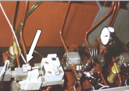
Fig. 6. View of electro-hydraulic proportional pressure valve connected in hydraulic circuit of loading device
Controlling signal
[image:5.595.306.533.563.724.2]type PV 3K-20 have accomplished parameters and required reliability.
For example when this type of hydrogenerator of size number 119 with mass 102 kg is used the maximum horsepower of the tested engine may be 205 kW in maximum pressure 40 MPa and maximum geometric volume VGmax = 118.7 cm3. The parameters mentioned above are without competition and let as try to compare them with electromotor. This cannot compare with that.
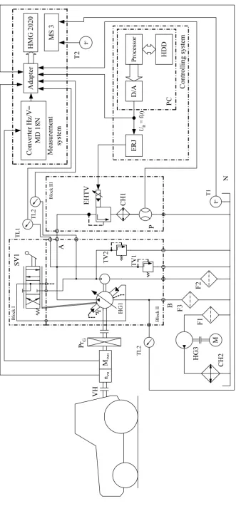
Generally the hydrostatic circuit shown in Fig. 8 may be divided into three block:
– Block I presents manually controlled servo-valve SV1 for adjustment of the geometric volume of the hydrogenerator HG1.
– Block II presents one-way controlled hydrogen-erator HG1 type PV 3K-20. Internal connection of this hydrogenerator is shown in Fig. 8. Input of the hydrogenerator HG1 is connected to the tank N by the filter F3. So called controlling hydro-generator is a component of the hydrohydro-generator HG1. The controlling hydrogenerator serves to hydraulic control of geometric volume VG of the hydrogenerator is connected to the tank N by the filter F2. The pressure valve TV1 is as a safety valve to protect the hydrogenerator against overload and valve TV2 serves to adjustment of controlling pressure.
– Block III presents electro-hydraulic proportional pressure valve EHTV type NW 10, cooler CH2 and flowmeter P (see Fig. 8).
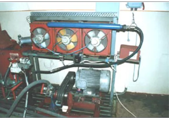
There is also a separate hydraulic circuit for cool-ing of hydraulic liquid (Fig. 7). The coolcool-ing circuit consists of hydrogenerator HG3, cooler CH2, filter F1 and electromotor M (Fig. 8).
After building of the loading device the hydraulic circuit mentioned above was tested by biodegradable oil EKOHYD 68 S.
RESULTS AND DISCUSSION
On the basic of obtained results during function-al tests of the designed loading device it is possible to state that all hydraulic circuits and elements are suitable for required functions and purposes. In comparison with other loading devices for example electrical designed device has some advantages. First of all this device is programmable that al-lows the loading of the tractor engine by various regimes. The next advantage is that the tractor engine may be tested without demounting of the engine. That is very advantageous mainly when tractors are tested in the operational conditions for long time. Generally in this case a horsepower of the tractor engine is measured after working of certain number of motorhours. The designed loading device also may be built as a portable type in various size according to the horsepower of trac-tor engine. From the advantages mentioned above it results that present hydraulic elements allow to build perfect loading devices equipped by modern measurement, controlling and recording equip-ment. In future the design loading device may be innovated and improved with respect to require-ments of research.
CONCLUSION
The loading device described in this paper will be used for measurement of speed and dynamic charac-teristics of tractor engines in laboratory conditions. We suppose that designed loading device makes easier and accelerates demanding experimental measurements. Also by using of this loading device accuracy of measurement will be higher as compared with present state.
[image:6.595.65.356.54.257.2]�
�
��
������
�
��
�
���
�
��
�
��
�
�
�
�
�
��
����
��
��
�
�
������ ��
��
�
�
�
�
�
�
�
�
�
�
�
�
�
��
��
���
�
�
�
��
��
����������
���
��
��
��
��
�
��
�
��
�
��
������
��
�
��
�
�
�������
���
��
��
��
�
�
�
��
��
��
���
�
��
�
�
�
�
��
��
�����
��
�
�
�
�
���
�
�
�
��
�
�
�
�
�
�
�
��
��
�
Fig
. 8. F
unc
tional s
cheme of t
esting de
vic
e f
or me
asur
emen
t of sp
ee
d and dy
namic c
harac
ter
istic
s of trac
tor eng
ine
[image:7.595.64.396.50.769.2]SYMBOLS
D/A – digital-analogue converter,
EHTV – electro-hydraulic proportional pressure valve,
ERJ – electronic control unit, F – filter,
HDD – hard disc, HG – hydrogenerator,
HMG 2020 – hand-held measuring unit HMG 2020 made by HYDAC,
CH – cooler, M – electric motor,
MS 3 – digital recording equipment type MS 3 made by COMET,
N – tank,
P – flow meter, PC – personal computer,
PrG – input gear box of hydrogenerator, PVH – power take off shaft gear box, SM – combustion engine,
SV – servo valve, T – thermometer, TL – pressure transducer, TV – pressure valve, VH – power take-off shaft.
References
AHP, 1999. Technické podmienky pre axiálne hydrostatické prevodníky – séria 3K-10. GTN T-005. Podnikový katalóg. (Axial hydrostatic transducers technical conditions – series
3K-10. Corporate catalogue.) Turčianske Teplice, AHP, a. s.: 33.
HP ENGINEERING, 2003. Axial piston pumps. Corporate catalogue.
PETRANSKÝ I., 1989. Hydrostatické simulátory dynamického zaťažovania mobilných energetických prostriedkov a ich uzlov. [Doktorská dizertačná práca.] Nitra, VŠP: 476. PETRANSKÝ I., DRABANT Š., ŽIKLA A., BOLLA M., TKÁČ
Z., KLEINEDLER P., 2004. Skúšobné stavy pre životnostné skúšky hydrostatických prevodníkov. [Vedecká monogra-fia.] Nitra, SPU: 164.
TKÁČ Z., ŠKULEC R., 2000. Aplikácia bioodbúrateľného oleja v prevodovom a hydraulickom systéme traktora. Košice, Acta Mechanica Slovaca, 6: 267–270.
TKÁČ Z., ŠKULEC R., HUJO Ľ., JABLONICKÝ J., 2001a. Skúška traktora s biologicky odbúrateľným olejom EKO-UNIVERZAL. In: III. mezinárodní vědecká konference mladých. Praha, ČZU: 127–132.
TKÁČ Z., ŠKULEC R., LENĎÁK P., VITÁZEK I., 2000. Sle-dovanie životnosti hydrogenerátora UN 10L.21 s biologicky odbúrateľnou kvapalinou. In: II. medzinárodná vedecká konferencia mladých 2000. Nitra, SPU: 80–89.
TKÁČ Z., ŠKULEC R., POKORNÝ K., 2001b. Elektroriadiaci systém traktora. In: Spoľahlivosť a kvalita strojov. 6. medzi-národné vedecké sympózium. Nitra, SPU: 211–213.
Received for publication August 5, 2005 Accepted after corrections September 1, 2005
Skúšobný stav s otvoreným hydrostatickým obvodom pre dynamické
zaťažovanie traktorových spaľovacích motorov cez vývodový hriadeľ
ABSTRAKT:V príspevku sú uvedené vývojové riešenia zaťažovacieho otvoreného hydrostatického zariadenia na meranie otáčkových charakteristík traktorových motorov a meranie ich dynamických charakteristík (vrátane prevádzkových) cez vývodový hriadeľ traktora. Tieto zariadenia je možné konštrukčne riešiť aj ako prenosné na meranie priamo v prevádzke. Pri vývoji v súčasnosti je možné u týchto zariadení využiť regulačné hydrogenerátory, čo umožňuje nastavenie geometric-kého objemu hydrogenerátora od nulovej až po maximálnu hodnotu a elektrohydraulické proporcionálne tlakové ventily riadené počítačom. Takéto zariadenia – 1 hydrogenerátor a 1 prepúšťací ventil – je možné postaviť do výkonu spaľovacieho motora 420 kW, čo je z praktického hľadiska dostatočné, a umožňujú využívať optimálne zaťažovacie režimy pre jednotlivé výkonové triedy traktorov a tak dosiahnuť maximálnu presnosť meraní.
Kľúčové slová:vývodový hriadeľ traktora; meranie otáčkovej charakteristiky; hydraulické kvapaliny; hydrostatické gene-rátory; elektrohydraulické proporcionálne tlakové ventily
Corresponding author:
Doc. Ing. ŠTEFAN DRABANT, CSc., Slovenská poľnohospodárska univerzita v Nitre, Mechanizačná fakulta, Katedra vozidiel a tepelných zariadení, Trieda A. Hlinku 2, 949 76 Nitra, Slovenská republika