Microstructural Evolution during Austenitization
and Quenching of a 5
%
Cr Work Roll
Minwoo Kang
1, Minsu Jung
1, Hyongjik Lee
2and Young-Kook Lee
1,+ 1Department of Materials Science and Engineering, Yonsei University, Seoul 120-749, Korea2Technical Research Laboratory, POSCO, 1, Goedong-dong, Nam-gu, Pohang, Gyeongbuk 790-785, Korea
The effects of a slow heating rate and a long austenitizing time with various cooling rates on the carbide dissolution and phase transformations of a 5%Cr work roll steel was investigated based on actual austenitization and quenching conditions and a large roll size using transmission and scanning electron microscopy, dilatometry, and thermodynamic calculations. When the roll temperature reached the austenitization temperature of 1173 K, the dissolution of pre-existing carbides was nearly complete due to the slow heating rate of 100 K/h, indicating that the austenite matrix had an equilibrium chemical composition at 1173 K before quenching. After quenching at cooling rates ranging from 0.1 to 3.0 K·s¹1along the radial direction of the roll, the core of the roll contained ferrite, pearlite, bainite and undissolved carbides,
while the surface consisted of martensite and undissolved carbides. [doi:10.2320/matertrans.M2012238]
(Received July 4, 2012; Accepted August 22, 2012; Published October 11, 2012)
Keywords: 5%chromium steel, austenitization, quenching, work roll, carbide dissolution
1. Introduction
Roll performance can be evaluated in many different ways depending on working conditions such as rolling temper-ature, thickness reduction, and friction. For cold rolling, the wear resistance of the roll is considered to be one of the most important properties to evaluate because the barrel part of a work roll undergoes a large amount of friction and load. Therefore, the lifetime of a work roll for cold rolling is greatly influenced by the wear property of the roll material, which depends on the matrix hardness, the size, amount, and hardness of the carbides, and the depth of the hardened layer. Due to the high hardness of the carbide precipitates, a high fraction of fine and randomly distributed carbides helps improve the wear resistance of the roll. The 5% Cr (in mass%) steel has been widely used as a cold work roll for its excellent hardenability and wear resistance, which can be attributed to M7C3-type Cr-rich carbides and MC-type V-rich carbides.15) Some amount of Ni in the 5% Cr steel also increases the austenite stability, enhancing the hardenability of the steel.
In general, the heat treatment process of cold work rolls consists of preliminary and final heat treatments.6) The purpose of the final heat treatment is surface hardening for wear resistance, and the final heat treatment is usually conducted by induction heating, spray-water quenching, and low-temperature tempering. The preliminary heat treatment is employed to endow the roll with machinability, hardness, toughness, and the proper microstructure for the final heat treatment. The preliminary heat treatment typically consists of spheroidizing annealing, austenitization and quenching, and high-temperature tempering.
There are many reports about the effects of Cr content, austenitizing temperature, and tempering conditions on microstructure, wear resistance, shock resistance, and fracture mechanisms in the 5% Cr roll steel.712) However, some studies were conducted with a short austenitizing time,10)a
fast heating rate,12)or a fast cooling rate,12)all of which are far from actual austenitizing and quenching conditions. In addition, many of the abovementioned studies were uncon-cerned with the heating or cooling rate and the austenitizing time.79,11)The large size of the cold work roll leads to a slow heating rate, a long austenitization time, and a severe gradient in the cooling rate between the surface and the core during quenching. Typically, the austenitizing time of the 5%Cr roll is more than 10 h, the heating rate is approximately 100 K/h in a gas furnace. The cooling rate varies from approximately 0.1 K·s¹1at the core to approximately 3.0 K·s¹1at the surface along the radial direction of the roll during quenching into an oil bath at 333 K in the actual quenching process.
Therefore, the present study was aimed at investigating the effects of a slow heating rate, a long austenitizing time, and various cooling rates during the preliminary heat treatment on the phase transformations and microstructure in the 5% Cr work roll steel. During the austenitization, a quantitative examination of the amount and size of carbides and the compositional change in the matrix was conducted based on image analyses and thermodynamic calculations using Thermo-Calc. After austenitization, the effect of the cooling rate on the decomposition of the austenite with varied chemical composition due to undissolved carbides was also investigated.
2. Experimental Procedure
A 50 kg ingot with the chemical composition listed Table 1 was made using a vacuum induction furnace. The ingot was homogenized at 1523 K for 3 h, hot-rolled to a plate of 30 mm thick at temperatures ranging from 1373 to 1523 K with a thickness reduction of approximately 80%, and then air-cooled to room temperature. The plate was spheroidized at 1143 K for 2 h, followed by furnace-cooling to room temperature.
To examine the microstructural change during austenitiza-tion, small specimens were heated to 1173 K at a rate of 100 K/h and held for 0, 5 and 11 h using a vacuum tubular
+Corresponding author, E-mail: yklee@yonsei.ac.kr
process due to the large size of the rolls.
Microstructures of the austenitized and quenched speci-mens, including precipitates, were observed using a fi eld-emission scanning electron microscope (FE-SEM, JEOL, JSM-7001F). The SEM samples were mechanically polished and then etched using a mixed solution of picral (4 g dry picric acid and 100 cm3 ethanol) and a few drops of concentrated hydrochloric acid (1 cm3per 100 cm3 of picral solution). To obtain quantitative information on the changes in amount and size of carbides with austenitizing time in the three different specimens, image analyses were conducted using ten SEM images taken at a magnification of 3000 at random locations of each specimen. The equilibrium fractions of carbides were calculated using a Thermo-Calc software (TCCS with TCFE7 database). Detailed analyses of carbides were conducted using a transmission electron microscope (TEM, JEOL, JEM-4010) equipped with an energy dispersive X-ray spectroscope (EDXS, Oxford, INCA Energy). Thin foils for TEM observations were prepared by twin-jet polishing at 288 K at conditions of 15 V and 20 mA in a mixed solution of 90% glacial acetic acid and 10% perchloric acid.
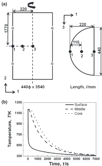
To investigate the variation of cooling rate along the radial direction of the roll during quenching, the finite-element (FE) calculation for quenching of the barrel part of a 5%Cr roll was performed using a commercialized FE software DEFORM·(version 10.0). Figure 1(a) shows the shape and dimension of the barrel part of the 5% Cr roll. A tetrahedral element was used and total numbers of nodes and elements were 7081 and 31629, respectively. The initial temperature of the roll was assumed to be 1173 K, and the quenchant (oil) temperature was given to be 233 K. The heat transfer coefficient as a function of surface temperature during oil quenching was quoted from a reference article13) and used as the boundary condition. The heat capacity and thermal conductivity of a 5% Cr steel were taken from the literature.14,15) Figure 1(b) shows the calculated cooling curves during quenching at three different positions: surface (0 mm), middle (110 mm) and core (220 mm), respectively. The cooling rate was between 1173 and 473 K was 0.24 K·s¹1 at the core, 0.28 K·s¹1 at the middle and 2.5 K·s¹1 at the surface, respectively. Experiments were conducted with the range of from 0.1 to 3.0 K·s¹1, wider than the range of calculated cooling rate, cooling rate during quenching of a roll should vary with size of roll and quenching conditions.
To investigate the decomposition behavior of austenite during the quenching after austenitization, dilatometric tests
were performed using a dilatometer (Theta, Dilatronic III). Dilatometric specimens measuring 3©1©1 mm3 were austenitized at 1173 K for 11 h in a vacuum chamber at 10¹3Pa and then cooled to room temperature at different rates of 0.1, 0.5 and 3.0 K·s¹1. Microstructures of the dilatometric specimens were observed using an optical microscope (OM, Olympus, BX41M) and the FE-SEM. The volume fraction of retained austenite at room temperature was measured using X-ray diffraction (XRD) with Cu-K¡ radiation, a scanning range of 40 to 100°, and a scanning speed of 2°/min.
3. Results and Discussion
3.1 Microstructural change during austenitization
Figure 2(a) shows a FE-SEM image of the 5% Cr work roll spheroidized at 1143 K for 2 h before austenitization. The microstructure consisted of lamellar pearlite, degenerate pearlite, and spheroidized pearlite. The broken lamellar carbides, which were located between lamellar and sphe-roidized pearlite regions, seem to be degenerated from pre-existing lamellar carbides during spheroidization, indicating incomplete spheroidization. The carbides were classified into four different types according to their shape and size: lamellar, broken lamellar, spherical, and tiny spherical. The broken lamellar (Fig. 2(b)) and spherical (Fig. 2(d)) carbides were identified as Cr-rich M7C3 carbides with a hexagonal
(b)
[image:2.595.322.527.68.403.2] [image:2.595.47.289.104.159.2]crystal structure from their selected area diffraction patterns (SADP) in Figs. 2(c) and 2(e). As reported in the previous work,16)tiny spherical carbides of less than 50 nm (Fig. 2(f )) are deemed to be V-rich M(C,N) carbides with a face-centered cubic (fcc) structure, which was confirmed by the EDXS spectrum shown in Fig. 2(g).
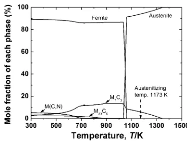
The 5%Cr content prevented the formation of cementite, thus enhancing the precipitation of M7C3 carbides as was expected from both an FeCrC ternary phase diagram17)and equilibrium fractions of carbides calculated by Thermo-Calc. As shown in Fig. 3, the austenitizing temperature signifi -cantly affects the equilibrium fractions of carbides. The equilibrium fraction of M7C3 carbide in the austenite of 1173 K was 5.1% (mole fraction), corresponding to approx-imately 5%volume fraction.
Fig. 2 SEM micrograph of the spheroidized specimen showing three different carbide morphologies (a), bright-field TEM micrographs indicating broken-lamellar (b), spherical (d), andfine spherical carbide (f ). The corresponding SAD patterns (c) and (e) of the broken-lamellar and spherical carbide in (b) and (d), respectively, and the EDXS spectrum (g) offine spherical carbide in (f ).
[image:3.595.136.461.65.544.2] [image:3.595.332.516.622.761.2]To examine the microstructural change during the austenitization of the spheroidized specimen, specimens were held at 1173 K for 0, 5 and 11 h and then quenched in water at room temperature. The microstructure of the quenched samples consisted of the martensite matrix with dispersed undissolved spherical carbides regardless of the austenitizing time, as shown in Fig. 4. With increasing austenitizing time, some carbides, which are marked by black arrows, were elongated and enlarged along the grain boundaries, and carbide-depleted zones were produced near these ripened particles, implying that the austenite grain boundaries provided a dominant diffusion path of Cr for the particle
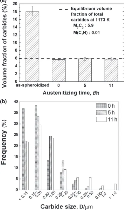
ripening. Quantitative analyses of both the volume fraction (Fig. 5(a)) and the size distribution (Fig. 5(b)) of the carbides were conducted.
As shown in Fig. 5(a), the pre-existing carbides in the spheroidized specimen were almost completely dissolved and reached the equilibrium volume fraction during heating to 1173 K due to the slow heating rate of 100 K/h. In addition, there was no significant change in the volume fraction of the carbides with further austenitizing time. This result implies that the dissolution of carbides wasfinished, and the austenite matrix had the equilibrium chemical composition before quenching, regardless of austenitizing time (i.e., regardless of the location inside the roll). Considering the fact that the measured volume fractions of carbides were very close to the equilibrium volume fractions (a dotted line in Fig. 5(a)), the austenite matrix austenitized at 1173 K is thought to have the equilibrium chemical composition of austenite at 1173 K as calculated by Thermo-Calc, which is Fe0.53C3.17Cr 0.40Mn0.33Si0.52Ni0.31Mo (in mass%, as shown in Table 1).
Figure 5(b) shows the change in the size distribution of carbides with austenitizing time at 1173 K. When the austenitizing time was 0 h, the volume fraction of fine
Fig. 4 SEM micrographs showing undissolved carbides in water-quenched specimens, which were held at 1173 K for (a) 0 h, (b) 5 h and (c) 11 h before quenching. Black arrows indicate relatively large carbides, which were located at the grain boundaries.
(b)
[image:4.595.62.280.65.579.2] [image:4.595.321.532.76.433.2]particles less than 0.20 µm was approximately 75%. When the austenitizing time was increased to 5 h, the fraction of the fine particles significantly decreased to approximately 56%. With further holding to 11 h, the fraction of fine particles continued to decrease, and some particles had an average size of larger than 1 µm, most likely due to Ostwald ripening.18)
3.2 Austenite decomposition during quenching
To investigate the effect of cooling rate after austenitiza-tion on phase transformaaustenitiza-tions and final microstructure, dilatometric tests were performed with different cooling rates after austenitization at 1173 K for 11 h, and the resultant dilatometric curves are shown in Fig. 6. The start temper-atures of ferrite (Ar3), pearlite (Ar1), bainite (Bs), and martensite transformations (Ms) were determined as the temperatures where the dilatational curve started to deviate from the tangential lines. When the cooling rate was as slow as 0.1 K·s¹1, the Ar3was approximately 1059 K, that of the Ar1 was near 965 K, and that of the Bs was approximately 706 K. Although the total carbon concentration was as high as 0.9 (in mass%), it is thought that the ferrite transformation started from the carbon-depleted austenite near undissolved carbides during austenitization at 1173 K. When the cooling rate was 0.5 K·s¹1, the B
[image:5.595.322.528.68.249.2]swas decreased to 665 K and that of the Ms was approximately 523 K with nearly no ferrite and pearlite transformations. When the cooling rate was increased to 3.0 K·s¹1, only the martensite transformation occurred, and the Ms slightly decreased to 513 K. The measured Ms temperature was very close to the Ms (513.3 K) temperature predicted by the Andrew’s product equation19) using the equilibrium chemical composition of austenite at 1173 K, as shown in Table 1. This result means that a critical cooling rate for full martensite was between 0.5 and 3.0 K·s¹1.
Figure 7 shows the XRD pattern of the specimen cooled at a rate of 3.0 K·s¹1 after austenitization at 1173 K for 11 h. There were no peaks diffracted from the fcc austenite phase. Accordingly, the volume fraction of retained austenite in the quenched specimen was inappreciable, indicating that there was no retained austenite.20)
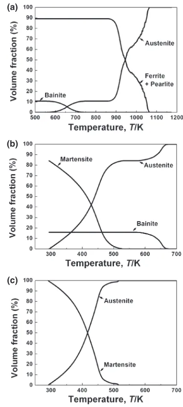
The change in the volume fraction of each phase with temperature during cooling at different rates from 1173 K was
quantitatively obtained by applying the lever rule to the measured dilatometric curves, as plotted in Fig. 8. For the cooling rate of 0.1 K·s¹1, the austenite decomposed to ferrite,
Fig. 6 Dilatometric curves measured during cooling of the specimens at different cooling rates of 0.1, 0.5 and 3.0 K·s¹1after austenitization at
1173 K for 11 h. Fig. 7 XRD diffraction pattern of the specimen cooled at a rate of 3.0 K·s¹1
after austenitization at 1173 K for 11 h.
(a)
(b)
(c)
Fig. 8 Change in the volume fraction of each phase during cooling at different cooling rates of (a) 0.1, (b) 0.5 and (c) 3.0 K·s¹1 after
[image:5.595.64.277.68.224.2] [image:5.595.330.517.290.705.2]pearlite, and bainite. However, it was difficult to distinguish between the ferrite and pearlite transformations. The total volume fraction of ferrite and pearlite was 89% and that of bainite was 11% at room temperature. At the cooling rate of 0.5 K·s¹1, bainitic and martensitic transformations occurred, giving rise to a microstructure consisting of 16%bainite and 84% martensite. At the cooling rate of 3 K·s¹1, the fully martensite phase was obtained.
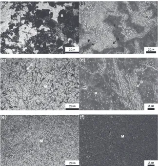
To confirm the microstructure predicted from dilatometric data, the microstructures of the specimens cooled at various rates from 1173 K were analyzed using a dilatometer and are shown in Fig. 9. In these micrographs, F is ferrite, P is pearlite, B is bainite, and M is martensite. In all of the samples, the retained austenite was not discernible, as was expected from the XRD result (Fig. 7), and many undis-solved carbides were observed. For the cooling rate of 0.1 K·s¹1 (Figs. 9(a) and 9(b)), the resulting microstructure contains ferrite, fine lamellar pearlite, and bainite. For the cooling rate of 0.5 K·s¹1 (Figs. 9(c) and 9(d)), the bainite with a branch-like morphology was transformed at the austenite grain boundaries, and the other matrix was martensite. The full martensite matrix with undissolved carbides was observed in the specimen cooled at 3.0 K·s¹1 (Figs. 9(e) and 9(f )). Direct observations of the micro-structure of the specimens cooled at different cooling rates showed good agreement with the microstructure predicted from the dilatation curves.
The austenitization and quenching processes examined in the present study belong to the preliminary heat treatment, which does not have direct effects on the surface wear properties. However, the preliminary heat treatment endows a roll with proper microstructures along the radial direction of the roll. The core part of the roll consists of pearlite with a good balance of strength and ductility to withstand huge mill loads.6) On the other hand, the surface part needs high hardness to endure abrasive wear. The surface hardening treatment is conducted through induction hardening in most cases. The initial microstructure for induction hardening is tempered martensite, which lowers the austenitizing temperature to avoid excessive austenite grain growth, and enhances wear properties.21) From the austenite decomposi-tion kinetics measured in the present study, a critical cooling rate for the pearlite matrix at the core part should be slower than 0.1 K·s¹1. While a critical cooling rate for the martensitic matrix at the surface part should be faster than 0.5 K·s¹1.
4. Conclusions
The volume fraction of the pre-existing carbides before austenitization was decreased to be almost equal to the equilibrium fraction at the austenitizing temperature when the temperature reached the austenitizing temperature of 1173 K with a slow heating rate of 100 K/h. This result indicates that
[image:6.595.136.462.69.409.2]the long austenitization time at 1173 K did not cause further carbide dissolution, but it did cause carbide coarsening. The austenite matrix also reached the equilibrium chemical composition before quenching. The critical cooling rate for obtaining full martensite was between 0.5 and 3.0 K·s¹1. From the above-mentioned results, it was realized that the large-sized 5% Cr work roll, which was austenitized at 1173 K for over 10 h and quenched into an oil bath, had various microstructures along the radial direction: the core part had ferrite, pearlite, bainite and undissolved carbides, while the surface had martensite and undissolved carbides.
Acknowledgement
The authors gratefully acknowledge the financial and material support from POSCO, Pohang, Korea.
REFERENCES
1) M. Hashimoto, T. Tanaka, T. Inoue, M. Yamashita, R. Kurahashi and R. Terakado:ISIJ Int.42(2002) 982989.
2) S. Iwadoh and T. Mori:ISIJ Int.32(1992) 11311140.
3) J. McCann: Ironmak. Steelmak.27(2000) 1518.
4) Q. Zhou, X. Wu and N. Min:Met. Mater. Int.17(2011) 547552.
5) M. Kim, S. Park and B. Lee:J. Kor. Inst. Met. Mater.48(2010) 194 202.
6) G. A. Ott: Proc. Conf. on 33th Mechanical Working and Steel Processing, (Iron and Steel Society, Saint Louis MO, 1991) pp. 159 170.
7) D. N. Hanlon, W. M. Rainforth and C. M. Sellars: Wear203204
(1997) 220229.
8) J. V. Khudorozhkova and S. V. Burov: Proc. Conf. on 3rd Int. Forum on Strategic Technologies, (IFOST, Novosibirsk, Tomsk, 2008) pp. 4144. 9) K. Kim, K. Nam, G. Kwak and S. Hwang:Int. J. Fatig.26(2004) 683
689.
10) A. A. Polushin, V. I. Gryzunov, S. V. Kamantsev and M. Y. Minakov:
Met. Sci. Heat. Treat.51(2009) 404407.
11) A. Ray, M. S. Prasad, P. K. Barhai and S. K. Mukherjee:J. Mater. Eng. Perform.14(2005) 194202.
12) Q. Wu, D. L. Sun, C. S. Liu and C. G. Li:Eng. Fail. Anal.15(2008) 401410.
13) S.-J. Lee and Y.-K. Lee:Acta Mater.56(2008) 14821490.
14) F. Cverna:Thermal Properties of Metals, (ASM International, Ohio, 2002) p. 225.
15) F. Cverna:Thermal Properties of Metals, (ASM International, Ohio, 2002) p. 342.
16) Q. Wu, D. L. Sun and C. S. Liu:J. Mater. Eng. Perform.18(2009) 952958.
17) L. R. Woodyatt and G. Krauss:Metall. Mater. Trans. A7(1976) 983 989.
18) S. C. Jain and A. E. Hughes:J. Mater. Sci.13(1978) 16111631.
19) K. W. Andrews: J. Iron Steel Inst.203(1965) 721727.
20) B. D. Cullity and S. R. Stock:Elements of X-ray diffraction, (Prentice Hall, Upper Saddle River, NJ, 2001) p. 355.
21) K. D. Clarke, C. J. Van Tyne, C. J. Vigil and R. E. Hackenberg: