Abstract— This study focuses on the manufacture of carbon nanotubes using the arc discharge method. Several independent variables were changed, such as the current (80 and 100 A), an atmosphere of open air or argon and the catalyst (no catalyst, Fe or a mixture of Fe/Co,Ni). Only one set of parameters yielded MWNTs, involving Fe as the catalyst and an open air atmosphere.
Index Terms— carbon nanotubes, MWNTs, arc discharge
I. INTRODUCTION
There has been intensive research into the production of carbon nanotubes in recent years as they are novel nanoparticles with unique properties that promise advances in a diverse number of areas, such as electronics, reinforced composites, functionalised materials and biomedical applications. There are three main types of synthesis of carbon nanotubes: arc discharge, laser ablation and chemical vapour deposition. Table 1 presents some typical characteristics for each technique in terms of yield, whether they favour the production of single-walled (SWNTs) or multi-walled (MWNTs) and the nanotube diameter.
Table 1. Features of different techniques for the synthesis of carbon nanotubes
Arc Discharge
Laser Ablation
CVD
Yield 30-90% <70% 20-100%
Diameter SWNT 0.6-1.4nm 1-2nm 0.6-4nm
Diameter MWNT
1-3nm - 12-240nm
The arc discharge technique involves an easy set up while it is possible to produce high yield. This was the method originally used by Iijima [1] for the production of buckyball structures
Manuscript received March 5, 2007
All authors: School of Engineering, University of Surrey, Guildford, Surrey GU2 7XH, UK
and carbon nanotubes. It comprises the vaporisation of one of two carbon rods (one anode – positive and one cathode – negative), placed end-to-end, with a current passing through the pair. The high temperature of the discharge causes the consumption of one of the rods. The consumed rod (anode) can be found deposited on the end of the other rod (cathode) in the form of a sort of soot, occasionally described as a ‘cigar-like’ structure, that contains nanotubes. A ‘bowl’ shaped cathode used by Huang [2] has the added advantage that it allows for a greater surface area, decreasing the defects and producing cleaner nanotubes, and also acts as a good collector. The rods must be kept at a constant distance apart of approximately 1-2mm.
Use of an inert gas at 500-700 mbar in a chamber has been made on occasion while this chamber also helps to avoid the loss of some of the ‘soot’ produced and reduce contamination. The inert gas can be a pure gas or it can be a mixture of a number of them. Typical gases used include argon, helium, hydrogen and methane [3]. The purity and yield of the nanotubes produced was found to depend on the gas pressure in the chamber by Ebbesen and Ayayan [4], where a He/Ar gas was used at a variety of pressures to conclude this result. The method has now been performed in open air using a Ni/Y catalyst composition [5]. This experiment successfully produced single-walled nanotubes and carbon nanohorns (a nanotube with one closed end and one open end). This maintains simplicity and keeps costs low as a chamber is not then required to perform the vaporisation.
A catalyst is often used to help with the synthesis of single-walled nanotubes as it promotes their growth, reducing the number of layers in the carbon nanotubes. Therefore it can be controlled whether they are SWNTs or MWNTs. Typically, the catalyst will be a transition metal such as Fe, Co, Ni, Pt, Pd, S, Y, Mo or a combination of them [2,3,6].
Both AC and DC currents have been used, the effect of which depends on the other variables in the experiment. The uniformity of the nanotubes produced and, hence, the yield depend greatly on the uniformity of the arc between the two rods.
Manufacture of Carbon Multi-Walled Nanotubes
by the Arc Discharge Technique
Fig.1 presents a diagram of the set up used in the arc discharge technique.
Fig.1. Diagram of the arc discharge technique
The two electrodes were from POCO graphite, purchased from Erodex: a ¼ inch diameter rod was placed in the welding gun as anode and a ½ inch diameter rod was fixed with a clamp at the base as the cathode. The cathode was either from POCO
graphite or it also contained a catalyst. Two alternative catalysts were used: Fe at 2 at% [7] or a mixture of Fe, Co, Ni at a composition of 1.45, 0.7, 2.6 at% respectively [6]. The metals were provided as powders of about 10 μm particle size. Holes of 3 mm diameter were drilled in the ½ diameter rods. The carbon substance removed or lost through the drilling process was ground into a fine powder for use in the mixing with the catalyst powders. After the powder of the appropriate carbon/catalyst composition was prepared, it was used to fill the hole of the cathode rod. The powder was compacted with the aid of a smaller blunt rod.
[image:2.595.39.547.471.522.2]After the electrodes were secured, the welding gun was held directly over the lower rod at 2 mm distance. Subsequently, it was switched on for 5 min during each run. Afterwards, the samples were left to cool for a few minutes before the samples were then collected carefully, so as not to spill soot that had accumulated on the edges and top of the cathode. They were placed into a specimen tube for transfer to the microscopy laboratory where they were examined by SEM and TEM. Table 2 presents the different parameters that were changed in the various runs for the manufacture of carbon nanotubes.
Table 2. Independent variables in the experimental runs of the arc discharge technique
Run: A1 A2 A3 A4 B1 B2 B3
Catalyst None None None None Fe Fe, Co, Ni Fe, Co, Ni
Atmosphere Open air Open air Argon Argon Open air Open air Argon
Current 80A 100A 80A 100A 80A 80A 80A
III.RESULTS AND DISCUSSION
Run A1
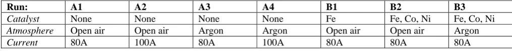
SEM showed no interesting features. A few nanoropes of about 50 nm diameter were present in TEM micrographs (see Fig.2) but they were scarce and it was not possible to obtain an image at higher magnification to examine them further. As a result, the current was increased for Run A2 in the hope that this might yield nanotubes.
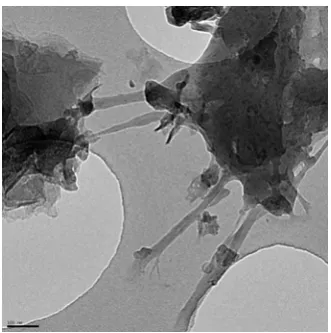
Run A2
Fig. 2 Run A1: TEM micrograph
Runs A3 and A4
There were no particular features on the SEM micrographs.
(a)
[image:3.595.332.529.332.508.2](b)
Fig.3: Run A2: (a) SEM micrograph; (b) TEM micrograph
Run B1
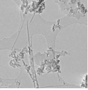
At the end of this run the tip of the anode was visibly worn away and a substantial deposit was accumulated on the cathode. At the tip of the cathode, just above the hole where the catalyst was placed, the SEM revealed a plethora of fibrous features, thought to be nanotubes (see Fig.4(a) and (b)). This was confirmed by further investigations under TEM, presented in Fig.5(a)-(d).
(a)
[image:3.595.72.246.368.712.2](b)
large quantities.
The TEM images show a large number of the nanotubes have been produced as when examining the sample under the microscope they were abundant in number, most adequately demonstrated in Fig.5(a). Fig.5(b) shows a close up of these nanotubes confirming that these are, in fact, multiple-walled nanotubes. It also demonstrates the impurities attached to the side of the nanotube, thought to be fullerenes (this can be judged from their size). The fullerenes should be removed through some form of purification in order to make use of these nanotubes.
Fig.5(c) shows the cap of the nanotube. Here it can be seen that there is no catalyst on the tip. This illustrates that the growth mechanism for this experiment was root growth and not tip growth. The catalyst was probably left on the rod when this sample was removed for the examination.
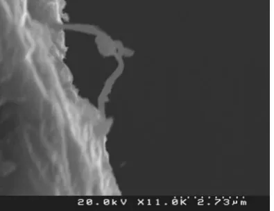
evidence of nanotubes, although a few particular features appeared, presented in Fig.6 and 7.
IV. CONCLUSIONS
This is an interesting study as it resulted in the production of nanotubes by the arc discharge technique in the open air. Previous studies yielded nanotubes in this manner using a Y-Ni catalyst [5]. Carbon nanotubes were produced in our study using Fe as catalyst: they consisted of MWNTs of about 15 nm diameter. Yield was not measured in our study and it will be part of future work.
(a) (b)
[image:4.595.61.432.320.702.2](b) (d)
Fig. 5: Run B1; TEM micrographs:
[image:4.595.65.216.329.483.2]Fig. 6 Run B2; SEM micrograph Fig. 7 Run B3; SEM micrograph
REFERENCES
1. S.Iijima “Helical microtubules of graphitic carbon” Nature, 354, 1991, pp.56-58.
2. H.Huang et al “Large-scale rooted growth of aligned super bundles of single-walled carbon nanotubes using a direct arc plasma method” Chemical Physics Letters, 343, 2001, pp.7-14.
3. Y.Saito et al “Growth conditions of double-walled carbon nanotubes in arc discharge”, J.Phys.Chem. B, 107, 2003, pp.931-934.
4. T.W.Ebbesen and P.M.Ajayan “Large scale synthesis of carbon nanotubes” Nature, 358, 1992, pp.220-222. 5. H.Takikawa et al “Fabrication of single-walled carbon nanotubes and nanohorns by means of a torch arch in open air” Physica B, 323(1-4), 2002, pp.277-279. 6. J.L.Hutchison et al “Double-walled carbon walled
nanotubes fabricated by a hydrogen arc discharge method” Carbon, 39, 2001, pp.761-770.