Abstract— This paper a new method for the control of Two link- robotic manipulator systems using Neural Network has been presented, The first method is based on Proportional-Derivative controller, The second method is based on Proportional-Integral-Derivative controller, the third method is based on artificial Neural Network by PD controller, and the forth method is based on artificial Neural Network by PID controller for control of Two link- robot.
Index Terms — Two link- robotic manipulator systems, Neural Network, PD controller, PID controller.
I. INTRODUCTION
In the recent years using intelligece control such as fuzzy control, Neural Network, Neuro Fuzzy and because that they can control nonlinear systems that would be difficult or impossible to model mathematically. In the recently years In Dynamic control of robot have been utilized in many researchers work in this area. Such as Lianfang Tian et al use a neural network approach for the motion control of constrained flexible manipulators robots [1].
Yi , et al have investigated the robustness and stability of a fuzzy logic controller applied to a robotic manipulator with uncertainties such as friction, unmodeled dynamics, and external disturbance etc [2], Kumbla et al have implemented hierarchical control on robotic manipulator using fuzzy logic [3].
Bannerjee, et al have used a Fuzzy Logic Controller to achieve position control of a two-link manipulator [4]. Adams, et al [5] has used GA to optimize the membership functions and rule bases of a multi-stage fuzzy PID controller with a fuzzy switch for robot control. Brudka, et al presented an intelligent robot control system which employs ultrasonic distance measurements, and for
Consecutive stages of data processing they used to neural networks applications [6], Adamiv, et al
used neural networks application for mobile robot control on predetermined trajectory of the road [7], Ya-Chen , et al used an Fuzzy neural adaptive controller to multiple-link robot control [8], Devendra P, et al used the proportional plus derivative (PD) control with the PD controller gain parameters optimized via Genetic Algorithm (GA) And Fuzzy Logic for control of Two link- robot [9], Z.G. Zhang, et al report on the design and stability analysis of a simple quadruped running controller that can autonomously generate steady running with
Dongbing Gu, et al presented a new path-tracking scheme for a car-like mobile robot based on neural
predictive control, they employed A multi-layer back-propagation neural network to model non-linear kinematics of the robot instead of a linear regression estimator in order to adapt the robot to a large operating range [10], Mathew L, et al studied on the implementation of several Intelligent control techniques as applied to the balancing of the inverted wedge problem. These included a basic four-input direct fuzzy controller (including the use of the nonlinear input term) and an adaptive fuzzy control technique known as the FMRLC [11].
II. DYNAMIC EQUATION OF TWO LINK- ROBOTIC MANIPULATOR SYSTEMS [12]
[image:1.595.334.536.581.720.2]In this section we derive the equations of motion for an individual link based on the direct method has been derived, i.e. Newton-Euler Formulation. The motion of a rigid body can be decomposed into the translational motion with respect to an arbitrary point fixed to the rigid body, and the rotational motion of the rigid body about that point. The dynamic equations of a rigid body can also be represented by two equations: one describes the translational motion of the centroid (or center of mass), while the other describes the rotational motion about the centroid. The former is Newton's equation of motion for a mass particle, and the latter is called Euler's equation of motion.
Figure 1 shows all the forces and moments acting on link i.
Fig. 1: Free body diagram of link i in motion
Neural Network Controller Based on PID
Controller for Two links- Robotic Manipulator
Control
Let be
V
ci the linear velocity of the centroid of link i withreference to the base coordinate frame O-xyz, which is an
inertial reference frame. The inertial force is then given by ci
i
V
m
.
−
, wherem
i is the mass of the link andV
ci .is the time derivative of
V
ci.Based on D’Alembert’s principle, the equation of motion is then obtained by adding the inertial force to the static balance of forces in eq.( 1) so that
. 1
, ,
1
−
++
−
=
0
− i ii i i ci
i
f
m
g
m
V
f
,i
=
0
,
1
,...,
n
(1)
i i
f
−1, and−
f
i,i+1are the coupling forces applied to link i bylinks i-1 and i+1, respectively, and g is the acceleration of
gravity.
Adding these terms to the original balance of moments we have:
0
)
(
)
(
)
(
1, , 1, , , 1 .1 , ,
1
−
+−
−−
×
−+
−
×
+−
−
×
=
− i ii i i ici i i ici ii i i i i i
i
N
r
r
f
r
f
I
I
N
ω
ω
ω
(2)
i i
N
−1, and−
N
i,i+1are the moment applied to link i by links i-1 and i+1, respectively.
If we consider two individual links robot, Let us obtain the Newton-Euler equations of motion for the two individual links.
Fig.2: Mass properties of two planar robots
From eq. (1) and (2), the Newton-Euler equations for link 1 are given by:
. 1 1 1 2 , 1 1 ,
0
−
f
+
m
g
−
m
V
c=
0
f
(3)0
)
(
)
(
0,1 0,1 1,1 1,2 1 .1 2, 1 1 ,
0
−
N
−
r
×
f
+
r
×
f
−
I
ω
=
N
c (4)Note that all vectors are 2 x 1, so that moment N i-1,i and the
other vector products are scalar quantities. Similarly, for link 2, . 2 2 2 2 ,
1
+
m
g
−
m
V
c=
0
f
(5)0
)
(
1, 2 1,2 2 .22 ,
1
−
r
×
f
−
I
ω
=
N
c (6) To obtain closed-form dynamic equations, we first eliminate the constraint forces and separate them from the joint torques, so as to explicitly involve the joint torques in the dynamic equations. For the planar manipulator, the joint torques τ1 and τ2 are equal to the coupling moments:i i i
N
−1,=
τ
(7)Substituting eq.(7) into eq.(6) :
0
)
(
)
(
1,2 2 2 . 2 2 .22
−
×
−
−
ω
=
τ
r
cm
V
cm
g
I
(8)Similarly, eliminating
f
0,1 yields,
(
)
(
)
(
)
(
)
0
. 1 1 2 1 , 0 . 1 1 , 0 2 2 1 , 0 . 1 1 1 ,0 2
1
−
τ
−
×
+
×
+
×
+
×
−
ω
=
τ
r
cm
V
cr
m
V
cr
cm
g
r
m
g
I
(9)Next, we rewrite
V
ci,ω
ci andr
i−1,iusing jointdisplacements
θ
1,
θ
2 which are independent variables. Note thatω
2 is the angular velocity relative to the base coordinate frame, whileθ
2 is measured relative to link 1. Then, we have. 2 . 1 2 1 .
1
θ
,
ω
θ
θ
ω
=
=
+
(10) The linear velocities can be written as⎥
⎥
⎥
⎦
⎤
⎢
⎢
⎢
⎣
⎡−
=
)
cos(
)
sin(
1 . 1 1 1 . 1 1 1θ
θ
θ
θ
c c cl
l
V
(11){
}
{
}
⎥
⎥
⎥
⎥
⎦
⎤
⎢
⎢
⎢
⎢
⎣
⎡
+
−
+
+
+
−
+
+
−
=
. . 2 2 1 2 1 2 1 2 1 1 . . 2 2 1 2 1 2 1 2 1 1 2)
cos(
)
cos(
)
cos(
)
sin(
)
sin(
)
sin(
θ
θ
θ
θ
θ
θ
θ
θ
θ
θ
θ
θ
θ
θ
c c c c cl
l
l
l
l
l
V
(12) 1 . 2 . 1 . 2 2 12 .. 1 111
=
H
θ
+
H
θ
−
h
θ
−
2
h
θ
θ
+
G
τ
(13)2 .
1 ..
1 21 ..
2 22
2
=
H
θ
+
H
θ
−
h
θ
+
G
τ
That:
2 2 2 1 2 2 2 1 1 1 2 1 1
11
m
l
I
m
(
l
l
2
l
l
cos(
))
I
H
=
c+
+
+
c+
cθ
+
2 2 2 1 22
m
l
I
H
=
c+
(14)
2 2 2 1 2 2 2
11
m
(
l
l
l
cos(
))
I
H
=
c+
cθ
+
)
sin(
22 1
2
l
l
cθ
m
h
=
(15))
cos(
1 22 2
2
=
m
g
l
cθ
+
θ
G
(16)III. NEURAL NETWORK CONTROLLER BASED ON PID AND PD
CONTROLLER [13, 14, 15, 16]
This paper presents two strategies for achieving the control in two link- robotic manipulator systems. First one is based on Proportional plus Derivative (PD) controller with its control by use Neural Network controller based on PD controller. The performance of a PD controller depends upon the proportional gain (Kp) and derivative gain (Kd). Dependent upon the values of Kp and Kd are the stability, settling time, maximum overshoot and many other system performance indicators. The transform function of PD controller that used in this paper is [16]:
(17)
In this paper a PD controller is used in control of Two link- robotic manipulator systems, The block diagram of a PD controllers is shown in Figure 3.
System
T1 q1
T2 q2
PD
CONTROLLER
+
-PD
CONTROLLER
+
-+
-+
Artificial neural network can be applied to various problems such as function approximation, pattern recognition, signal processing, classification, etc. Appendix I shows the more details about general view on artificial neural network. There are typically two steps involved when using neural networks for control:
1-System identification 2-Control design
In the system identification stage, you develop a neural network model of the plant that you want to control. In the control design stage, you use the neural network plant model to design (or train) the controller. In each of the three control architectures described in this chapter, the system identification stage is identical.
The model predictive control method is based on the receding horizon technique. The neural network model predicts the plant response over a specified time horizon [14, 16];
The Neural Network controller based on PD controller has been used for control of Two link- robotic manipulator systems, The block diagram of a Neural Network controllers based on PD controllers is shown in Figure 4.
Neural Network Controller
Refrence
Neural
Network
Model
PD
Controller
+
-+ -+
-output
-+
+
-+
[image:3.595.310.514.338.484.2]Plant output
Fig. 4: the structure of the Neural Network controller
The second strategy is based on Proportional-Integral-Derivative (PID) with its control by use Neural Network controller based on PID controller both of these strategies are briefly described below:
PID stands for Proportional-Integral-Derivative. This is a type of feedback controller whose output, a control variable (CV), is generally based on the error (e) between some user-defined set point (SP) and some measured process variable (PV). Each element of the PID controller refers to a particular action taken on the error:
Proportional: error multiplied by a gain, Kp. This is an adjustable amplifier. In many systems Kp is responsible for process stability: too low and the PV can drift away; too high and the PV can oscillate. Integral: the integral of error multiplied by a gain, Ki. In many systems Ki is responsible for driving error to zero, but to set Ki too high is to invite oscillation or instability or integrator windup or actuator saturation Derivative: the rate of change of error multiplied by
)}
cos(
)
cos(
{
)
cos(
1 2 2 1 2 1 11 1
1
m
l
g
θ
m
g
l
θ
θ
l
θ
G
=
c+
c+
+
S
K
K
S
[image:3.595.48.269.598.742.2]response: too high and the PV will oscillate; too low and the PV will respond sluggishly. The designer should also note that derivative action amplifies any noise in the error signal.
The transform function of PID controller that used in this paper is:
(18)
In this strategy PID controller is used in control of Two link- robotic manipulator systems, The block diagram of a PID controllers is shown in Figure 5.
System
T1 q1
T2 q2
PID
CONTROLLER
+
-PID
CONTROLLER
+
-+
[image:4.595.308.525.83.242.2]-+
Fig. 5: the schematic of PID Controller
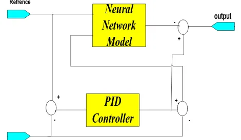
The Neural Network controller based on PID controller has been used for control of Two link- robotic manipulator
systems, The block diagram of a Neural Network controllers
based on PID controllers is shown in Figure 6.
Refrence
Neural
Network
Model
PID
Controller
+
-+ -+
-output
-+
+
[image:4.595.60.269.227.377.2]
-+
Fig. 6: the structure of the Neural Network controller based on PID controllers
The structure of Neural Network controller based on PID controller and PD controller that used in control of Two link- robotic manipulator systems, is shown in figure 7.
System
T1 q1
T2 q2
Neural Network
Controller
Neural Network
Controller
[image:4.595.304.529.407.559.2]
Fig. 7: the schematic of Neural Network controller
In Neural Network controller as learning rules Modified Levenberg-Marquardt has been used [13,15].
IV. SIMULATION RESULT
In the first the dynamic model of two link- robotic manipulator systems has been simulated using Matlab software 2007 as you see the system is unstable. Figure 8 shows the schematic of Two link- robotic manipulator systems and figure 9 shows the simulation result for step input:
Fig. 8: the schematic of the Two link- robotic manipulator systems
1
)
(
+
+
+
=
NS
S
K
S
K
K
S
G
D [image:4.595.55.290.454.591.2]Fig. 9: the output of two link- robotic manipulator systems
As the first method for closed loop control of two link robot the PD controller has been used, figure 10 shows the simulation result
Fig. 10: the output of two link- robotic manipulator systems using PD
controller
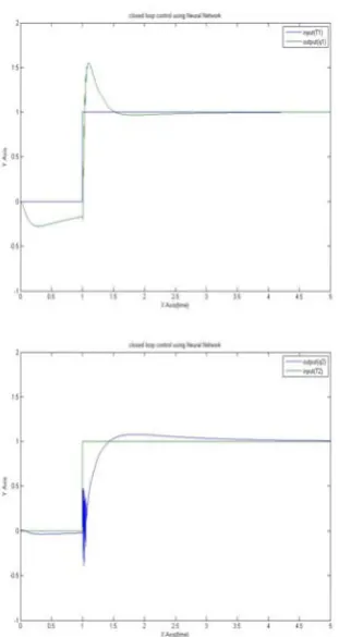
[image:5.595.66.275.86.247.2]As the second method closed loop control of robotic manipulator systems the Neural Network controller based on PD controller has been used, figure 11 shows the simulation result:
Fig. 11: the output of two link- robotic manipulator systems using Neural Network controller based on PD controller
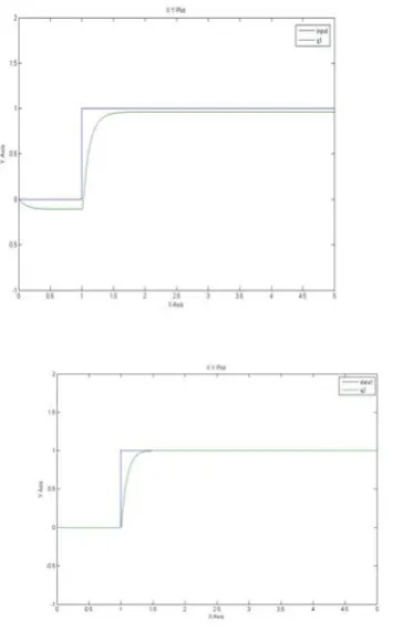
As the third method for closed loop control of two link robotic manipulator systems the PID controller has been used, figure 12 shows the simulation result:
Fig. 12: the output of two link- robotic manipulator systems using PID controller
[image:5.595.73.251.339.625.2] [image:5.595.317.523.493.631.2]Fig. 13: the output of two link- robotic manipulator systems using Neural Network controller based on PID controller
[image:6.595.259.544.233.746.2]The following table shows the comparison between these methods:
Table I: comparison between these methods for Link 1
Q1 Rise Time
Settling Time
Oversh oot
Unders hoot
Peak Time
Steady state error PD 0.250
5
1.4787 0 11.056 5
5 0.0373
PID 0.157 9
2.5076 36.265 4
28.952 3
1.5632 7.4895e-006
Neural Network& PID
0.023 6
2.1768 55.160 2
27.431 4
1.1056 0.0016
Neural Network & PD
0.399 5
2.9504 0.0028 12.638 3
4.1000 0.0513
Feedback compensat or by pid
0.528 0
4.8189 0.3823 0 4.9493 5.9849e-007
Table II: comparison between these methods for Link 2
Q2 Rise Time
Settling Time
Oversh oot
Undersh oot
Peak Time
Steady state error
PD 0.19 63
1.3412 0.0022 0.1013 1.9256 1.5413e-004 PID 0.32
31
3.1904 16.935 4
0.6991 1.8029 2.1544e-004
Neural Network & PID
0.31
07 3.0221 7.2733 38.4734 1.8361 0.0057
Neural Network & PD
0.47
76 2.9797 0.0036 1.3076 3.8699 0.0123
V. CONCLUSION
This paper presents 4 method for the control of Two link- robotic manipulator systems, The first method is based on Proportional-Derivative controller, The second method is based on Proportional-Integral-Derivative controller, and the thirth method used artificial Neural Network by PD controller, and the forth method used artificial Neural Network by PID controller for control of Two link- robotic manipulator systems.
REFERENCES
[1] Lianfang Tian, Jun Wang, and Zongyuan Mao, "Constrained Motion Control of Flexible RobotManipulators Based on Recurrent Neural Networks" IEEE TRANSACTIONS ON SYSTEMS, MAN, AND CYBERNETICS—PART B: CYBERNETICS, VOL. 34, NO. 3, JUNE 2004 [2] Yi, S.Y. and Chung, M., J., 1997, “A Robust Fuzzy Logic Controller for
Robot Manipulators with Uncertainties”, IEEE Transactions on Systems, Man and Cybernetics, 27, No. 4, pp. 706 – 713.
[3] umbla, K.K. and Jamshidi, M., 1994, “Control of Robotic Manipulator Using Fuzzy Logic”, Proceedings of the Third IEEE Conference on Fuzzy Systems, Vol. 1, pp. 518-523.
[4] Bannerjee, S. and Woo, P.Y., 1993, “Fuzzy Logic Control of Robot Manipulator”, IEEE Conference on Control Applications, pp. 87-88.
[5] Adams, J.M. and Rattan, K.S., 2001, “Genetic Multi-Stage Fuzzy PID Controller with Fuzzy Switch”, Proceedings of the IEEE International Conference on Control Applications, pp. 323-327.
[6] Brudka, M. Pacut, A., “Intelligent robot control using ultrasonic measurements" Proceedings of the 16th IEEE Instrumentation and Measurement Technology Conference, 1999. IMTC/99.
[7] Adamiv, O. Koval, V. Turchenko, I., “Predetermined movement of mobile robot using neural networks" Proceedings of the Second IEEE International Workshop on Intelligent Data Acquisition and Advanced Computing Systems: Technology and Applications, 2003.
[8] Petropoulakis, L., " Intelligent control using agents and fuzzy behavioural structures" : Proceedings of the 2000 IEEE International Symposium on Intelligent Control, 2000.
[9] Ya-Chen Hsu Guanrong Chen Malki, H.A., " Fuzzy neural adaptive controller design: with application to multiple-link robot control" IEEE International Conference on Neural Networks, 1997.
[10] Dongbing Gu and Huosheng Hu., “Neural Predictive Control for a Car-like Mobile Robot” International Journal of Robotics and Autonomous Systems, Vol. 39, No. 2-3, May, 2002.
[11] Mathew L. Moore, John T Musacchio1, Kevin M. Passino, “Genetic adaptive control for an inverted wedge: experiments and comparative analyses” Engineering Applications of Artificial Intelligence 2001.
[12] H. Harry Asada, Introduction to Robotics. Massachusetts Institute of Technology.
[13] Hagan, M.T., Menhaj, M.B., “Training feed forward networks with the Marquardt algorithm”, IEEE Transactions on Neural Networks. 5:6, page(s): 989-993, 1994.
[14] Hagan, M.T., Demuth, H.B., Beale, M., Neural networks design. Boston, 1996.
[15] Suratgar, A.A., Tavakoli, M.B., Hosseinabadi, A., “Modified levenberg-marquardt neural network training”, Enformatika, Page(s):46-48, 2005.
[image:6.595.39.294.457.614.2]