Design Analysis of a New On-Board Computer for the
LAICAnSat Platform
DE MELO, Ana Carolina Cabral Pimentel, GUIMARAES, Fernando Cardoso,
HONDA, Yago Henrique Melo, BORGES, Renato Alves, HADDAD, Sandro
Augusto Pavlik, BATTISTINI, Simone <http://orcid.org/0000-0002-0491-0226>
and CAPPELLETTI, Chantal
Available from Sheffield Hallam University Research Archive (SHURA) at:
http://shura.shu.ac.uk/24827/
This document is the author deposited version. You are advised to consult the
publisher's version if you wish to cite from it.
Published version
DE MELO, Ana Carolina Cabral Pimentel, GUIMARAES, Fernando Cardoso,
HONDA, Yago Henrique Melo, BORGES, Renato Alves, HADDAD, Sandro Augusto
Pavlik, BATTISTINI, Simone and CAPPELLETTI, Chantal (2019). Design Analysis of
a New On-Board Computer for the LAICAnSat Platform. 2019 IEEE Aerospace
Conference.
Copyright and re-use policy
See
http://shura.shu.ac.uk/information.html
Design Analysis of a New On-Board Computer for the LAICAnSat
Platform
Ana C. C. P. de Melo, Fernando C. Guimar˜
aes, Yago H. M. Honda, Renato A. Borges
Department of Electrical Engineering
University of Bras´ılia
Bras´ılia, DF - Brazil 70310-900
+55 61 31071040
ana.cpmelo95@gmail.com, fernando3guimaraes@gmail.com,
yagohonda11@gmail.com, raborges@ene.unb.br
Sandro A. P. Haddad, Simone Battistini
Faculdade Gama
University of Bras´ılia
Gama, DF - Brazil 72444-240
+55 61 31078901
sandrohaddad@unb.br
simone.battistini@aerospace.unb.br
Chantal Cappelletti
Department of Mechanical Materials and Manufacturing Engineering
The University of Nottingham
University Park, Nottingham - NG7 2RD
+44 01157486848
chantal.cappelletti@nottingham.ac.uk
∗September 6, 2019
Abstract
The present work describes the new requirements for LAICAnSat project, a high altitude platform (HAP) developed at University of Brasilia (UnB). An anal-ysis of previous missions and a detailed comparison with respect to the previous OBC version is presented to assist with the design decision making. More specifically, a study of mission lifecycle is conducted
∗
to evaluate power consumption and a survey is car-ried out in order to estimate new power demands.
Contents
1
Introduction
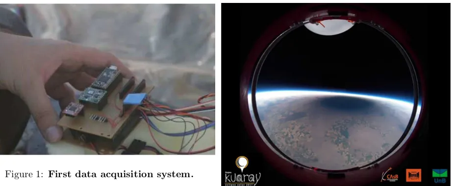
Univer-Figure 1: First data acquisition system.
sity of Brasilia (UnB), has been developing a project aimed at integrating students from several engineer-ing fields, such as mechatronic, aerospace, electric and electronic. The main goal is to develop a low cost modular platform for high and low altitude ap-plications such as remote sensing, telecommunica-tions, scientific studies, and others. This platform, named LAICAnSat, is fabricated in accordance with the CubeSat standard [?] using rapid prototype tech-nologies.
Preliminary project efforts originated a fairly unso-phisticated electronic system, with components con-nected to a protoboard, arranged inside a styrofoam box [?], as can be seen in Fig. ??. This system pro-vided the realization of two successful first missions (LAICAnSat-1 and LAICAnSat-2), which leveraged researches and future developments in the project, including researches on trajectory control [?, ?] and a restructuring to the CubeSat standard [?].
Evolution came with a printed circuit board [?], with the purpose of satisfying the minimum elec-tronic system necessary for the accomplishment of the further four launches in 2017 (LAICAnSat-3, LAICAnSat-4, LAICAnSat-5 and LAICAnSat-5.1). The first ones were carried out to validate the system for the latter ones, which was concerned with the recording of the total solar eclipse from the strato-sphere in 2017 by the NASA Space Grant Eclipse Ballooning Project [?]. Fig. ?? shows a picture of
Figure 2: Total solar eclipse image obtained from stratosphere - NASA APOD on August 27th, 2018.
the shadow of the moon on the Earth surface ob-tained during the Kuaray mission.
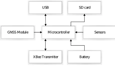
The first LAICAnSat on-board computer consists of a GNSS module, pressure and humidity sen-sors that also provide temperature measurements, a MEMS Motion sensor and a 3D accelerometer and magnetometer. Data is stored on an SD card and a XBee transmitter assures communication with ground station. Its flowchart can be seen in Fig. ??. Based on the analyses of these previous missions, several aspects related with the system development and integration were identified in order to be im-proved. Although inspired by the PC104 standard, the board does not provide connections for external devices, making it impossible to connect necessary components, as well as to integrate other subsystems. The microcontroller is an ARM Core M-4 repli-cated on a Teensy platform for educational purposes and it is going to be replaced for a processor with a more suitable development environment.
[image:3.612.85.546.122.312.2]acqui-Microcontroller USB
Battery Sensors
XBee Transmitter GNSS Module
[image:4.612.72.301.124.255.2]SD card
Figure 3: OBC Flowchart.
sition system.
A recurring problem during assembly of the sys-tem was the weight restriction, where the battery is largely responsible and its oversizing compromises full potential of the platform. In addition, the power supply was not well conditioned, including poor bat-tery protections and lack of health monitoring.
In this context, given the limitations of the PCB board, one of the next steps is to redesign the on-board computer (OBC), aiming to improve its performance and meet the additional demands, such as image processing, flotation control and attitude stabilization.
During past missions, there was a need for a bet-ter definition of the requirements, since the lack of management and traceability had negative effects on the project schedule and budget. Within this con-text, a system engineering approach based on NASA Systems Engineering Handbook [?] and similar works [?, ?, ?] served as a guide to assign well-established requirements, in order to unfold the user needs elici-tation into components and interfaces.
The methodology consists in a top-down descrip-tion of the system, allowing mission needs, goals and objectives to be mapped correctly and facilitating a bottom-up development process. Primarily, the mis-sion is defined in terms of objectives and external constraints are considered, such as size and weight, delimiting the boundary conditions. Thereafter, the concepts of operations (CONOPS) are defined,
pro-viding a better understanding of the behavior ex-pected. Lastly, system requirements are defined and unraveled into components and interfaces.
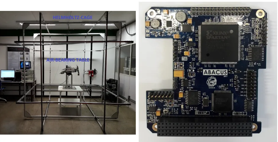
Simultaneous to LAICAnSat activities, the team has been developing a nanosatellite three-axis simu-lator facility. The simusimu-lator main components are an air-bearing table and a Helmholtz cage [?]. The fa-cility purpose consists in replicating the frictionless conditions encountered by satellites in space, besides the low gravitational torque and the Earth magnetic field perceived by them while in orbit. Therefore, the nanosatellite simulator allows the simulation, testing and validation of attitude determination and control algorithms, in addition to other spacecraft technolo-gies.
At this facility, a commercial OBC provided by the Italian company Gauss Srl, named ABACUS, is used to test algorithms and CubeSat hardware, such as magnetorquers, reaction wheels and communication modules. It is of interest to design the new OBC ca-pable of attending simulator demands to complement the use of the commercial one. Therefore, in this work a few tests were conducted with ABACUS and the air-bearing table to analyze the performance and power consumption of the microcontroller while run-ning known attitude determination algorithms pro-posed in [?].
This paper is organized as follows, Section 2 de-scribes the system as whole and its concepts of op-erations, used to raise the components required to accomplish the mission and its interfaces. Section 3 discusses tests conducted in the simulator to es-timate some parameters of resolution and sampling rate of the sensors, as well as the analysis of the per-formance of the microcontroller. Section 4 presents the requirements summary and the last section con-cludes discussion and presents future works.
2
System Definition
compati-ble, which establishes external constraints regarding to size (Units of 10cm cube), weight (1.33kg/Unit) and electrical connections. A flotation stage is be-ing planned to ensure scientific operations at high altitude. Therefore, it is necessary to ensure the op-eration of electronic systems at extreme temperature and pressure variations. A pressure valve prototype is being developed in-house for this purpose and will be tested in the next mission. Furthermore, the plat-form is designed to autonomously land in safe areas by performing a landing control.
The platform requirements are summarized below:
(1) A Command and Data Handling Subsystem (CDH) to monitor health conditions, store data and manage communications;
(2) A Control Subsystem to perform flotation and landing control;
(3) A Navigation Subsystem to track location and determine orientation;
(5) A Telemetry and Telecommand System (TTS) to communicate with ground stations;
(6) A satellite bus to accommodate and communi-cate with other subsystems;
(7) A flight software to manage operations and communication between subsystems and ground station;
(8) A format to store data packages acquired from sensors and log informations;
(9) Ground station to receive data and transmit commands;
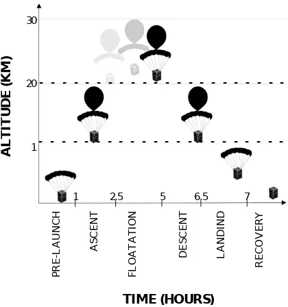
(10) The platform must be multiple of 10cm cube units (1U), with a mass budget of 1.33kg per unit. P R E -L A U N C H A S C E N T F L O A T A TI O N D E S C E N T L A N D IN D R E C O V E R Y TIME (HOURS) 30 20 1
1 2.5 5 6.5 7
A L T IT U D E ( KM )
-Figure 4: Mission lifecycle
2.1
Concepts of Operation
The life-cycle of the mission consists of six phases, as can be seen graphically in Fig. 4, named pre-launch phase, ascent and descent phases, floating, landing and recovery phases. The concepts of operation de-scribe the behavior of the system and helps to charac-terize the life-cycle of the mission and its operations as a sequence of events, shown in flowchart of Fig. 5.
2.1.1 Pre-launch preparation phase
The ground station is constructed, and vehicles are prepared. The latter step of this stage is to initiate electronic systems and validate its operation.
[image:5.612.310.520.122.346.2]2.1.2 Ascent phase
During this phase, the balloon flies freely, without control of any kind. In this mode, nominal oper-ations, which consists of characterizing internal en-vironment and monitor health conditions, such as temperature, pressure and power consumption take place. These data are properly formatted and stored to be sent to ground station by request at any time or in case of emergency situations to warn operators. The location is constantly monitored and transmit-ted at different rates, depending on the phase of the mission. It is important to note that this task of monitoring health conditions, as well as capacity to respond to ground station commands, both shaded in gray in Fig. ??, continuously run throughout the mission.
2.1.3 Flotation phase
Upon reaching 20 km, the operational phase starts, where the majority of missions are intended to be re-alized. The balloon is intended to float for approxi-mately two and a half hours, performing altitude con-trol through the pressure valve. The location must be transmitted at lower rates, housekeeping tasks are continuously running and images can be taken and stored;
2.1.4 Descent phase
After the float period, the pressure valve is now re-sponsible for deflating the balloon to a safe altitude in order to the landing control to be performed. The location must be transmitted at high rates and nor-mal operations are still running.
If at any time a state of emergency is detected, or if requested by the ground station, the platform with the parachute is released from the balloon and it will try to safely land on ground with using the parachute.
2.1.5 Landing phase
After reaching 1 km, the parachute is controlled to-wards a safe landing area within a set of possible ar-eas. The location must be transmitted at high rates.
2.1.6 Recovery phase
Recovering the platform is often complicated, so the energy must be saved given that conditions may not be favorable and reaching the platform may take some time. Therefore, as the platform hits the ground, storage is closed and all unessential subsys-tems are power-down and the location is transmitted at lower rates.
3
Simulator Requirements
This section describes the results of the tests con-ducted on the air-bearing testbed in order to eval-uate the table dynamics and microcontroller perfor-mance while running recognized attitude determina-tion algorithms. At a minimum, at least an inertial measurement unit (IMU) is required for the attitude determination applications in the simulator.
In Fig. 6 the on-board computer used as a refer-ence is mounted on the air-bearing table. This facility is described in more details in [?, ?]. The computer is the ABACUS OBC and Fig. ?? shows the board in details. This device has been tested in several mis-sions, including the Brazilian mission Serpens-1 [?].
Fig. ?? shows ABACUS mounted on the air-bearing table. Over ABACUS is placed a marker from the ArUco third party extension of OpenCV li-brary [?]. Using a web camera and the marker, the attitude of the table was determined by computer vi-sion software using the Euler angles representation. With the results it is possible to obtain boundaries for sensors resolution and sampling time.
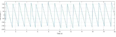
Fig. ??depicts the yaw angleversustime obtained in the first test. In this first experiment, the table was put into motion mainly about theZ axis and at the maximum speed allowable, considering the equip-ment safety. Since the X and Y axes have angular and velocity limitations compared to Z axis, the re-sults obtained are sufficient to affer boundaries for sensors parameters.
Fig. ?? shows that yaw angle oscillates contin-uously from −180o to 180o while the table rotates
Transmit images
Zero velocity? Parachute controls
N
Y
Landing
Transmit location
Power off other subsystems Recovery Pressure valve
MISSION OPERATIONS
Store data
2h duration? N Operational
Lower than 1km? Pressure valve
Descent
Request Location and HK measurements
Process and store data
Transmit location
Higher than 20km? N
Ascent POWER ON
Inicialize components
Transmit request
Transmit data Ground Signal
N
Y Prep
1
1 2 3 4
2 3
Ground command
Emergency signal Ground
command
Emergency
4 Ejection
N
Y Y
Y
[image:7.612.72.595.122.323.2]Y N
Figure 5: Mission flowchart
[image:7.612.71.575.124.620.2]Figure 6: Nanosatellite simulator overview.
[image:7.612.76.546.383.624.2]Figure 8: ABACUS and an ArUco marker mounted on the testbed.
Figure 9: Yaw angle of the table.
about−235o/s.
Considering a sampling time quite below the Nyquist limit, for example, ten times lower than the smallest period, a sampling interval of 100ms would be appropriate for the simulator. The angular ve-locity value of −235o/s implies in a range of about
±235o/sfor the rate gyro. Furthermore, in several al-gorithms the angular velocity is integrated over time in order to estimate the attitude angles. Thus, since the attitude determination system accuracy is smaller than 1o, a desirable maximum resolution value for the
rate gyro would be 10o/s because 10o/s×0.1s = 1o.
The maximum resolution values for the other IMU sensors can not be easily evaluated considering that they do not directly estimate the attitude. Therefore, the relationship between these sensors characteristics and the attitude estimation accuracy depends on the algorithms.
Table 1: Summary of boundaries for IMU Parameter Boundaries
Interface I2C/SPI
Sampling rate 100ms
Rate gyro range ±235o/s Rate gyro maximum
resolution value 10
[image:8.612.324.518.135.237.2]o/s
Table 2: Current consumption and execution time
Test Current (mA) Exec. time (ms)
TRIAD 18.4 1.91
USQUE 18.5 64.62
The resulting requirements obtained for IMU are summarized in Table??.
Further tests evaluated the current consumption and the execution time of ABACUS while running two attitude determination algorithms. The first is the TRIAD algorithm and the second is the Un-scented Quaternion Estimator (USQUE) proposed in [?]. Both methods were implemented in C language for MSP430 in the context of the work presented in [?]. The execution time for the algorithms shown in Table ?? correspond to one sample time, therefore, the value defined earlier of 100ms for the sampling interval is suitable for TRIAD and even USQUE ex-ecution. For TRIAD, the sampling interval can be much smaller.
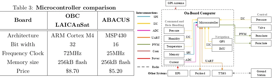
[image:8.612.95.286.352.413.2]Table 3: Microcontroller comparison
Board OBC
LAICAnSat ABACUS
Architecture ARM Cortex M4 MSP430
Bit width 32 16
Frequency Clock 72MHz 25MHz
Memory size 256kB flash 256kB flash
Price $8.70 $5.20
4
On-board computer
Require-ments
Considering requirements presented in section 2, the platform subsystems are translate as commercial off-the-shelf (COTS) components and interfaces, shown in Fig. ??. According to flowchart of Fig. ??, the OBC shall:
• Transmit its location throughout the flight at different rates depending on the phase of the mission, as well as store it for later reconstruc-tion of the trajectory;
• Monitor the internal environment conditions and be able to evaluate integrity of the system;
• Manage data and communication with subsys-tems that are integrated with it;
• Perform floatation and landing control;
• Be capable of responding to ground station commands at any time, to transmit data, to per-form maneuvers or to abort mission if requested;
• Be able to validate attitude determination and control algorithms simulated on air-bearing ta-ble.
TT&S Payload
UART Microcontroller
Pressure
Humidity
Temperature
Memory GPS Antenna
Current I2C
SPI
ADC UART
I2C
PWM ADC SPI
Coax
Command and Data Handling
Control
IMU GPS
Navigation
Pressure
Valve
Parachute
Parachute PWM
I2C On-Board Computer
Interconnections
EPS Other Systems
I2C
Power
Ground Station Radio
Figure 10: System description
A recurring problem exposed in previous sections was the oversizing of the battery that negatively in-fluenced the weight budget. In fact, it was found that given current system consumption (80mA), the bat-tery would be able to supply power for approximately 30 hours, while the mission lasts only seven. Thus, an estimation of the consumption of the new system was carried out, considering the new components to be added.
The Command and Data Handling and the Nav-igation Subsystems are inherited from previous pro-posals, maintaining same pressure sensor (Bosch BMP180) and GNSS module (uBlox LEA M8T). Hu-midity sensor (Sensirion SHT15) must be changed since the line used will be discontinued. The IMU considered in this analysis is InvenSense MPU-9250, which meets the requirements listed in Table ??. A current monitor should be added to analyze battery behavior and evaluate power consumption through-out the mission.
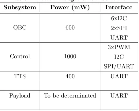
Table 4: Power Budget and Interfaces Subsystem Power (mW) Interface
OBC 600
6xI2C
2xSPI
UART
Control 1000
3xPWM
I2C
SPI/UART
TTS 400 UART
Payload To be determinated UART
only in their specific moments. With this solution, a power consumption of approximately 600mW is esti-mated for OBC, with additional 1W for sensor and actuators.
An exclusive module for the Telemetry and Telecommand System (TTS) system will be designed, and it is one that consumes more power, being able to vary from 400mW to 2W. [?]
Table ?? exposes systems power budget and in-terfaces required. With this survey, OBC consump-tion is estimated as approximately 600mW. With the additional subsystems, the consumption increases to 2W, without considering payload. Thus, the currently used battery (Nanotech 6.6V / 2100mAh Transmitter Pack) is suitably sized for the seven-hour mission of validating new systems, as it pro-vides 1.98Wh. However, consumption should be bet-ter evaluated afbet-ter their development and validation. Regarding the sensors, the microcontroller must have four to six I2C inputs and at least two SPI. The current monitor uses analog input and is converted by the microcontroller ADC. It is also necessary to secure the interface with the valve pressure sensor, through an I2C output and with the GPS antenna, through a coax connector.
In addition, it is desired that it has a development environment that allows high and low level
program-ming, in order to optimize firmware. It needs to have a built-in non-volatile memory to store the firmware and a boot mechanism that allows remote updating of the firmware.
The microcontroller used in previous tests is able to satisfy these demands of both interfaces and power consumption.
5
Summary
The new HAP embedded system has been described in terms of user requirements and unraveled into com-ponents and interfaces. Considering the testbed ap-plications, the OBC should have six PWM outputs, three for reaction wheels and three for magnetor-quers. During the missions, three PWM outputs are necessary for control systems. For communica-tion with the payload and the transmission system, at least two UART outputs are required. Upcom-ing developments include designUpcom-ing a printed circuit board, as well as its assembly, test and integration with other subsystems.
The minimum specifications required for the mi-crocontroller were shown in table??. It is interest-ing to note that the microcontroller MSP430, besides having presented satisfactory performance in the de-termination of attitude, it presents additional inter-esting characteristics that brings benefits to the plat-form balloon missions. It consumes approximately ten times less than the current microcontroller and has additional 16kB SRAM. Also, a Direct Memory Access controller allows movement of data without CPU intervention and a dedicated peripheral module supports 32-bit multiplication operations. Moreover, it also presents configurations of low power modes that would allow the power management in case of missions of longer duration.
unreliable measurements.
As the transmitter will be removed from the OBC, it will be necessary to design a dedicated module for communication with the ground station. As well as a power subsystem, with its proper protections and balancing, capable of providing outputs of 5V and 3.3V to power all subsystems.
For the time being, the current battery specifica-tions meet initial planning of a seven-hour mission to validate the subsystems described. However, there is an interest in carrying out missions of longer dura-tions depending on the performance of the pressure valve. In this case, a study on power generation and power management should be carried out if needed.
6
Acknowledgements
The authors thank the Brazilian agencies CAPES, CNPq and FAPDF for supporting this work.
References
[1] A. Mehrparvar, D. Pignatelli, J. Carnahan, R. Munakata, W. Lan, A. Toorian, A. Hut-putanasin, and S. Lee, “CubeSat Design Speci-fication - Rev. 13,” The CubeSat Program - Cal Poly SLO, February 2014. [Online]. Available: http://www.cubesat.org/s/cds rev13 final2.pdf
[2] P. H. D. Nehme, R. A. Borges, C. Cappelletti, and S. Battistini, “Development of a meteorol-ogy and remote sensing experimental platform: The LAICAnSat-1,” in Proceedings of the 35th IEEE Aerospace Conference, 2014, pp. 1–7.
[3] B. H. A. Noronha, A. V. S. Silva, R. A. Borges, and S. Battistini, “System identifica-tion of a square parachute and payload for the LAICAnSat,” in Proceedings of the 36th IEEE Aerospace Conference, 2015, pp. 1–7.
[4] M. A. L. Holanda, R. A. Borges, Y. M. Honda and S. Battistini, “Trajectory control system for the LAICAnSat-3 mission,” inProceedings of the 38th IEEE Aerospace Conference, 2017, pp. 1–7.
[5] M. F. S. Alves, A. P. Wernke, F. C. Pereira, D. H. Gomes, G. S. Lion¸co, C. H. F. L. Domin-gos, D. B. da Trindade, C. Cappelletti, M. N. D. B. J´unior, S. Battistini, and R. A. Borges, “Design of the structure and reentry system for the LAICAnSat-3 platform,” inII Latin Ameri-can CubeSat Workshop, 2016, pp. 1–15.
[6] R. R. Dias, A. K. de Castro, S. Battistini, R. A. Borges, and C. Cappelletti, “LAICAnSat-3: A mission for testing a new electronic and teleme-try and tracking system,” in Proceedings of the 2nd Latin American IAA CubeSat Workshop, 2016, pp. 1–9.
[7] R. A. Borges, L. T. de M. Corrˆea, S. C. Guimaraes, A. C. dos Santos, S. Battistini, and C. Cappelletti, “LAICAnSat-5: A mission for recording the total solar eclipse from the stratosphere,” in Proceedings of the 39th IEEE Aerospace Conference, 2018, pp. 1–7.
[8] R. Shishko and R. Aster, “Nasa systems engi-neering handbook,” NASA Special Publication, vol. 6105, 1995.
[9] S. A. Asundi and N. G. Fitz-Coy, “Cubesat mis-sion design based on a systems engineering ap-proach,” inIEEE Aerospace Conference,, 2013, pp. 1–9.
[10] T. E. O’Brien, “Space situational awareness CubeSat concept of operations,” Master’s the-sis, Naval Postgraduate School, Monterey, Cali-fornia., Dec. 2011.
[11] J. Straub, C. Korvald, A. Nervold, A. Moham-mad, N. Root, N. Long, and D. Torgerson, “Openorbiter: A low-cost, educational proto-type cubesat mission architecture,” Machines, vol. 1, no. 1, pp. 1–32, 2013.
[13] J. L. Crassidis, “Unscented Filtering for Space-craft Attitude Estimation,” Journal of Guid-ance, Control, and Dynamics, vol. 26, no. 4, pp. 536–542, Jul. 2003.
[14] R. C. Silva, F. C. Guimar˜aes, J. V. L. Loiola, R. A. Borges, S. Battistini, and C. Cappel-letti, “Tabletop testbed for attitude determina-tion and control of nanosatellites,” Journal of Aerospace Engineering, 2018.
[15] J. V. L. Loiola, L. C. van der Ploeg, R. C. Silva, F. C. Guimar˜aes, R. A. Borges, G. A. Borges, S. Battistini, and C. Cappelletti, “3 axis simula-tor of the Earth magnetic field,”IEEE Aerospace Conference, Mar. 2018.
[16] G. F. de Oliveira, P. D. Nehme, and C. Cappel-letti, “Analysis and simulation of attitude deter-mination and control for the serpens nanosatel-lite,” inProceedings of the 2nd IAA Conference on Dynamics and Control of Space Systems, International Academy of Astronautics, Roma, Italy, 2014.
[17] S. Garrid-Jurado, R. Mu˜noz-Salinas, F. J. Madrid-Cuevas, and M. J. Mar´ın-Jim´enez, “Au-tomatic generation and detection of highly reli-able fiducial markers under occlusion,” Pattern Recognition, vol. 47, no. 6, pp. 2280–2292, 2014.
[18] F. C. Guimaraes, “Implementation of Attitude Determination Techiques for a Small Satellite Three-axis Simulator,” Master’s thesis, Univer-sidade de Bras´ılia/PPGENE.DM - 703/2018, Jul. 2018.
[19] P. Muri and J. McNair, “A survey of commu-nication sub-sytems for intersatellite linked sys-tems and CubeSat missions ,”Journal of Com-munications, vol. 7, no. 4, pp. 290–308, 2012.
Ana Carolina Cabral Pimentel de Melo re-ceived her B.S. degree in Electrical Engeneering from Universidade Federal do Rio Grande do Norte in 2017. She is currently a M.S degree student of the Postgraduate Program of Electronic Systems and Au-tomation (PGEA) at Universidade de Bras´ılia. Her
research interests are related with embedded systems and development of high altitude scientific platforms.
Fernando Cardoso Guimar˜aesreceived his B.S. degree in Mechatronics Engenieering from University of Bras´ılia in 2014. After working 2 years as an em-bedded systems development engineer, he obtained his Masters Degree at Universidade de Bras´ılia with focus in aerospace technologies for small satellites in 2018. He is affiliated with the Laboratory of Au-tomation and Robotics (LARA) and with the Labo-ratory of Aerospace Science and Innovation (LAICA) at the same university. His main research inter-ests are embedded systems applied to aerospace tech-nologies, spacecraft guidance, navigation and control, Lyapunov stability theory, robust control, stochastic modeling and filtering.
Yago Henrique Melo Honda received a B.S. degree in Aerospace Engineering from University of Brasilia (UnB) in 2018. He is currently a M.S degree student of the Postgraduate Program of Electronic Systems and Automation (PGEA) at University of Bras´ılia. His main research interests are related to numerical simulation, control systems and develop-ment of high altitude scientific platforms.
Renato Alves Borgesreceived a Master (2004) and Doctoral (2009) degree in Electrical Engineer-ing from the University of Campinas and a PhD de-gree in Electrical Engineering from the University of New Mexico (USA) (2009). From 2009 to 2011 he held a post-doctoral fellowship from the state of Sao Paulo Research Foundation working at the School of Electrical and Computer Engineering at the Univer-sity of Campinas. He is currently an assistant pro-fessor in the Electrical Engineering Department of the University of Bras´ılia and a control system re-searcher affiliated with the Laboratory of Automa-tion and Robotics (LARA) and the Executive Co-ordinator the Laboratory for Application and Inno-vation in Aerospace Sciences (LAICA) at the Uni-versity of Brasilia. His main research interests are Lyapunov stability theory, stability analysis of linear and nonlinear systems, modeling and control of rotat-ing body, dynamic system analysis under uncertainty, and development of high altitude scientific platforms.
Uni-versity of Brasilia (UnB) with honors in 2000 and a PhD degree in Microelectronics from Delft Uni-versity of Technology (Delft UniUni-versity of Technol-ogy - TUDelft, Electronics Research Laboratory) in 2006. From 2007 to 2010, he worked for Freescale Semiconductors as an integrated circuit designer en-gineer (Analog IC Designer). In 2010, he began his activities at the University of Bras´ılia (UnB) as Ad-junct Professor. He also participates in the Mas-ter’s program in Biomedical Engineering of the Facul-dade UnB Gama (FGA) and the Graduate Program in Electronic Systems and Automation (PGEA) of the Department of Electrical Engineering of the Uni-versity of Bras´ılia. In addition, he serves as tech-nical manager of the Design Center for Integrated Circuit projects, DFCHIP. His line of research in-cludes mixed-signal and analog integrated circuits, ultra low-voltage analogue signal processing for im-planted biomedical systems and high frequency ana-log circuits for UWB communication systems.
Simone Battistini received his BSc (2006) and MSc (2009) degrees in Control System Engineering from Sapienza Universit`a di Roma. He got a PhD in Aerospace Engineering (2013) from the Scuola di Ingegneria Aerospaziale della Sapienza Universit`a di Roma. In 2012 he was a visiting student at Tech-nion - Israel Institute of Technology. He is currently an assistant professor at the Faculdade Gama of Uni-versidade de Bras´ılia, Brazil. He is associated with the Laboratory of Aerospace Science and Innovation (LAICA) of Universidade de Bras´ılia. His main re-search interests are related with guidance, navigation and control of aerospace vehicles.
Chantal Cappelletti received a BSc (2005) in Aerospace Engineering, a MSc (2008) in Astronau-tical Engineering and a PhD (2012) in Aerospace Engineering all from Sapienza Universit`a di Roma (Italy). She is currently an Assistant Professor at University of Nottingham (UK), where she is affili-ated with the Nottingham Geospatial Institute. Pre-viously, she was an Assistant Professor at the Uni-versity of Brasilia (Brazil) and a visiting researcher at Morehead State University (USA). She is the co-founder of the Italian company GAUSS Srl. She has led 6 satellite projects in Italy (UNISAT program and others) and in Brazil (SERPENS, TuPOD). She was