http://www.scirp.org/journal/opj ISSN Online: 2160-889X
ISSN Print: 2160-8881
DOI: 10.4236/opj.2017.78B012 Aug. 10, 2017 86 Optics and Photonics Journal
Experimental Study of Multi Optical Parameter
Imaging Technology under the Fog Condition
Weiwei Feng, Ligang Chen
College of Aeronautical Engineering, Binzhou University, Binzhou, China
Abstract
A multi optical parametric imaging system is introduced and established in order to improve the contrast of object in the fog. A few targets are observed in the fog weather based on the system level radiation model of multi optical parametric imaging and the calibrated model parameters. The results show that the building’s windows can be distinguished clear in the linear polariza-tion, circular polarization and angle of polarization images because of the strong reflected polarization light of the glass; The vehicles in intersection can hardly be seen in the intensity image, and it is fuzzy in degree of linear polari-zation and angle of polaripolari-zation image because of the doped polaripolari-zation in-formation of trees near in fog; The circular polarization image raises the con-trast of the vehicles by 20% because the circle polarization of the trees is less in the fog.
Keywords
Multi Optical Parameter, Radiation Model, Polarization Imaging
1. Introduction
Recently, there are so Frequent Haze weather of many cities in China which af-fects not only people’s health but also the visibility and influence People’s Daily life at the same time, especially in the fields of the road traffic, sea targets moni-toring and aviation flight safety [1] [2] [3]. Many scholars have carried out the research on the target identification of smog weather. Using the basic principle of atmospheric scattering model and combining with the sunny weather of con-trast image, K Nayar drawn from several images of different concentration of fog scene structure, to achieve image enhancement purpose in 1999 [4]. In 2000, David B et al. carried out the optical polarization imaging experiment in smoke, and the results showed that the polarization imaging improved the contrast ratio How to cite this paper: Feng, W.W. and
Chen, L.G. (2017) Experimental Study of Multi Optical Parameter Imaging Tech-nology under the Fog Condition. Optics and Photonics Journal, 7, 86-91.
https://doi.org/10.4236/opj.2017.78B012
DOI: 10.4236/opj.2017.78B012 87 Optics and Photonics Journal of the image in the scattering medium [5]. Schechner, et al. Studied the parallel and vertical polarization direction of scene images in haze weather successively and analyze the target image, the result showed that image contrast [6] are in-creased obviously. Wang Yong and Tianquan Liang carried out the study of the linear polarization image recognition method by using 0˚, 60˚, 120˚ which are three different polarization directions of polarization radiation pattern, the ex-perimental results showed the method can more effectively to distinguish the distant goal, to improve the target image contrast and obtain the target distance information [7] [8].
Polarization remote sensing application in the field of astronomy is the earli-est use of polarization camera to get pictures of the earth’s surface polarization, the observation of different vegetation, and mineral surface polarization infor-mation work [9]. Light polarization inforinfor-mation can be expressed by Stokes vector (I, Q, U, V) T, in which I is the intensity of polarized light, Q, U represent x linear polarized light and y linear polarized light, V represents the circularly polarized light [10]. In current polarization remote sensing detection, the circu-lar pocircu-larization information is often ignored. For example, the EOSP instrument in the United States and POLDER in France only use polarizer to measure radia-tion informaradia-tion in different polarizaradia-tion direcradia-tions, so only the first three Stokes parameters [11] [12] can be calculated. In order to get the circular polari-zation information, the phase delay device is needed [13], such as cirrus detector (CCS) system which is developed by the Chinese academy of sciences Shanghai technology cirrus detector (CCS) with rotating quarter wave plate, the measur-ing system is a full polarization measurement without imagmeasur-ing which is aimed cirrus clouds as the main target and detection of other types of clouds and at-mospheric aerosols [14]. Compared with radiation intensity or linear polariza-tion degree of image detecpolariza-tion technology which are based on single parameter information, multiple optical parametric measurement imaging system this pa-per developed can simultaneously obtain the target’s multiple optical parametric image information such as intensity , polarization radiation, the partial radiation, linear polarization, circular polarization degree and polarization Angle, etc. tar-get recognition ability in the fog haze image can be improved by the test of the multidimensional data analysis.
2. Multi-Optic Parametric Measurement Imaging
System and Its Principle
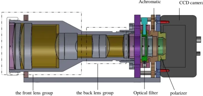
DOI: 10.4236/opj.2017.78B012 88 Optics and Photonics Journal Figure 1. The multi optical parameter imaging system.
quarter wave plate, polarizer, CCD surface array detector and image data pro- cessing software. The optical imaging lens is composed of the front group and the positive lens of the negative lens. The whole system is designed to minimize the imaging beam direction multiple optical parametric measurement error caused by the problem.
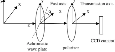
The direction of the optical axis of the multiple imaging optical parametric measurement system is Z-axis, and the transmission axis of plolarizer instru-ment is the X-axis, as shown in Figure 2.
According to the imaging propagation of polarization beam in optical polari-zation system, the radiation response of multi-optical parametric imaging sys-tem is obtained [15] [16]:
X = ⋅ +P S C (1) where S=(S S S S0, 1, 2, 3)
is the Stokes vector for the incident beam.
A n d
(
)
(
)
(
)
(
)
2 2
cos(2 )
cos(2 ) cos (2 ) 2 sin (2 ) cos( )
sin(2 ) sin(4 ) cos( )
2
2 sin(2 ) sin( )
q r q r
q r q r q r
P A q r
q r q r
q r α
α α α δ
α α δ
α δ + + − − + + + ⋅ = − + + − ⋅ − ⋅ i s
the measuring vector of the imaging system. Where A is absolute radiation ca-libration factor, α is the quick axial wave plate in absolute Angle in the coordi-nate system of the system. q and r are the transmission ratio of the two direction which are fast and slow axis respectively. Their ratio reflects the wavelength dichroism. δ is the actual phase delay of the achromatic lambda/4 wave plate.
C is dark current correction factor.
In this experiment measurement, the fast axis α in the coordinate system of the absolute Angle can varies continuously by rotating the achromatic λ/4 wave plate. And the radiation intensity output response can be obtained, and the li-near measurement equation can be established as show in the Equation (2):
Xα′ = ⋅P Sα (2) CCD camera
polarizer the back lens group
the front lens group
Achromatic
DOI: 10.4236/opj.2017.78B012 89 Optics and Photonics Journal Figure 2. The images of relative intensity transmission coefficient.
where S is the normalized Stokes vector of the incoming beam. α takes six po-larization angles (0, π/6, π/3 π/2, 2π/3 and 5π/6), Xα′ =Xα−C is The output of the radiation measured when the average amount of dark current is deducted. The Stokes vector (I, Q, U, V) T of the incoming beam can be measured by Ma-trix operation Equation (2) and then the multi-optic parameters of the target are obtained such as intensity I, polarization radiation Ip, non-polarization radiation Inon, linear polarization degree LP, circular polarization degree CP and polari-zation Angle θ.
3. Multi-Optical Parametric Measurement
Imaging Experiments
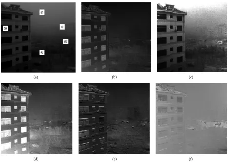
Using the multi-optic parametric measurement imaging system, we conducted a series of experiments on the smog of the sky, buildings and traffic intersections, As shown in Figure 3. The imaging work band is 750 nm.
Normally atmospheric media has strong polarization scattering properties, and its polarization scattering intensity is related to scattering Angle. In our haze weather scenario experiment, the distance the sky 1) is a large Angle backscatter, so the non-polarization radiation of the atmospheric scattering light radiation intensity is strong and polarization radiation is relatively weak. Building glass 2) of the total reflection energy is very weak, but the polarization of reflected light is relatively strong, we can all distinguish the window structure more clearly in the figures of linear polarization, circular polarization, polarization Angle. The non-polarization radiation of distant buildings 3) is stronger, and it mixed at-mospheric background light as a whole, so it is not easy to find. But the distant glass of building with little non-polarization radiation can be used to identify the target. In the scene of our experiment, the trees 4) has a certain amount of de-gree of linear polarization relative to the surrounding background, but its circu-larly polarized radiation information in haze weather has no particucircu-larly advan-tages of distinguish. For the cars at traffic intersection 5) the location, it is diffi-cult to identify these distant cars in the intensity figure. But they can be seen in the figures of the polarized radiation, linear polarization diagram and polariza-tion Angle, but the polarizapolariza-tion informapolariza-tion of nearby trees, makes the vehicle target is fuzzy. In the circularly polarized radiation figure, circular polarization information the nearby trees is less, so the vehicle target contrast can be in-creased by 20%, and the vehicle at the junction can be distinguish clearly.
x
x x
y y
α
z y
Achromatic
wave plate polarizer
DOI: 10.4236/opj.2017.78B012 90 Optics and Photonics Journal
(a) (b) (c)
[image:5.595.64.532.66.399.2]
(d) (e) (f)
Figure 3. The multi optical parametric imaging effect under the fog. (a) The intensity figure; (b) Polarized radiation figure; (c) non-polarization radiation figure; (d) Linear polarization figure; (e) Circular polarization figure; (f) The polarization Angle of figure.
4. Conclusion
DOI: 10.4236/opj.2017.78B012 91 Optics and Photonics Journal
Acknowledgements
This work is partly financially supported by two National Natural Science Foun- dation of China (Grant No. 41401384 and Grant No.41201368). This work is al-so financially supported by Science and technology development project of Shandong Province (Grant No. J14LJ02) and Research Foundation Program of Binzhou University (grant No. 2013Y09).
References
[1] Zhao, G.X., Du, L., Wei, L.P., et al. (2011) Comprehensive Analysis on a Durative Regional Haze and Fog. Arid Zone Research, 28, 871-878.
[2] Song, Y., Tang, X.Y., Fang, C., et al. (2003) Relationship between the Visibility De-gradation and Particle Pollution in Beijing. Acta Scientiae Circumstantiae, 23, 468- 471.
[3] Sheng, L.F., Liang, W.F., Qu, W.J., et al. (2001) Relationship of Aerosol Size Distri-bution and Visibility in a Sea Fog. Periodical of Ocean University of China, 41, 1-8. [4] Nayar, S.K. and Narasimhan, S.G. (1999) Vision in Bad Weather. The Proceedings
of the Seventh IEEE International Conference on Computer Vision, 2, 820. https://doi.org/10.1109/ICCV.1999.790306
[5] David, B.C.J. and Larry, P. (2000) Polarization Imaging through Scattering Media.
Proc. SPIE, 4133, 124-133. https://doi.org/10.1117/12.406619
[6] Schechner, Y.Y., Srinivasa, G.N. and Shree, K.N. (2003) Polarization-Based Vision through Haze. Applied Optics, 42, 511-525. https://doi.org/10.1364/AO.42.000511 [7] Wang, Y., Xue, M.G. and Hang, Q.C. (2009) Polarization Dehazing Algorithm
Based on Atmosphere Background Suppression. Computer Engineering, 35, 271- 275.
[8] Liang, T.Q., Zhao, Q., Sun, X.B., et al. (2014) Research on Image Restoration by Po-larized Remote; Sensing through Haze. Geomatics and Information Science of Wu-han University, 39, 244-247.
[9] Shi, Z.H. (2002) Polarization Imaging Measurement Technology and Its Applica-tion. Infrared, 4, 1-5.
[10] Chen, L.G. (2015) Polarimetric Calibration of the Polarization CCD Camera with Large Viewing Field. Opto-Electronic Engineering, 42, 15-20.
[11] Deschamps, P.Y., Herman, M., Podaire, A., et al. (1992) The POLDER Instrument: Mission Objectives. SPIE, 746, 72-91.
[12] Travis, L.D. (1992) Remote Sensing of Aerosols with the Earth Observing Scanning Polarimeter. SPIE, 1747, 154-164.
[13] Feng, W.W., Ma, G.L., Jia, T.J., et al. (2011) Measurement of Complete Stokes Pa-rameters of 2-D Plolarized Light. Laser Technology, 35, 715-717.
[14] Shao, W.D., Wang, P.G., Zheng, Q.B., et al. (2003) Polarimetric Calibration of Air-borne Remote Sensing Polarimeter. J. Infrared Millim. Waves, 22, 137-140. [15] Chen, L.G. and Feng, W.W. (2015) Study on System-Level Calibration of
Achro-matic λ/4 Wave-Plate. Journal of Applied Optics, 36, 905-908. https://doi.org/10.5768/JAO201536.0603001
Submit or recommend next manuscript to SCIRP and we will provide best service for you:
Accepting pre-submission inquiries through Email, Facebook, LinkedIn, Twitter, etc. A wide selection of journals (inclusive of 9 subjects, more than 200 journals)
Providing 24-hour high-quality service User-friendly online submission system Fair and swift peer-review system
Efficient typesetting and proofreading procedure
Display of the result of downloads and visits, as well as the number of cited articles Maximum dissemination of your research work
Submit your manuscript at: http://papersubmission.scirp.org/