Aerodynamic Model Analysis and Flight Simulation
Research of UAV Based on Simulink
Chao Yun, Xiao-Min Li
Department of UAV Engineering, Ordnance Engineering College, Shijiazhuang, China. Email: [email protected]
Received November 24th, 2012; revised December 25th, 2012; accepted January 3rd, 2013
ABSTRACT
Mathematical simulation method can be adopted to check flight characteristic of UAV, also can be adopted to simulate hardware experiments of unmanned aerial vehicle (UAV), then related flight experiments can be performed. The simu- lation method can reduce the flight periods, cost and risk. UAV flight model research play an important role in simula- tion and modeling in initialize periods of the UAV producing. The study of the paper focuses on the aerodynamic force modeling work of UAV based on Simulink. The designed model not only can afford mathematics simulation experi- ment but also will do benefits to the research of flight control, navigation guidance of UAV.
Keywords: Mathematical Simulation; Unmanned Aerial Vehicle (UAV); Aerodynamic Force; Simulink
1. Introduction
The UAV is getting more and more important with its increasing demand in war, now each country pays more attention to researching work of UAV, includes the early researching project, medium-term hardware simulation, performance validation, and simulation training. All above mentioned need the simulation research.
UAV plays more and more important role in modern war, which is a new form of the modern war. The re- searching work of kinematics characteristic is the basic work of the UAV system. The research work includes the simulation of flight track, guideline about and related techniques and tactics, the validation work through the simulation operation. Through high fidelity training for the UAV operator, UAV system will play more and more important role in its application field and heighten its fighting efficiency.
2. Simulation Technology of System
Simulation technology is based on conform principle, information technology and the technique of its applica- tion fields, it is a new all-around technology which is adopting computer and other physical equipments, and
make use of related model to do the experiments [1].
System simulation is an experimental method to acquire information through using the system model or assumed system. The basic actions of system simulation are mod- eling, simulation modeling and simulation experiments and experimental analysis. It not only can offer us ad- vanced methods to do the research working of analysis,
decision-making, designing and training, but also in- crease the cognitive ability for the extension inherent rule. It will promote the progress of the subject form qualita- tive analysis to ration. Now System simulation technol- ogy is widely used in the following research areas [2].
2.1. Application of System Analysis and Design
The system simulation technology could do the argu- mentation and feasibility analysis for the unfounded sys- tem, and do the basic work for system design. In the course of the system designing it can do help in building the model, and optimization designing work; when the system is built, we could look for optimal control law for the system through analysis results of the system.
2.2. Application of Theory Research
The theory research of the system mainly depends on theoretic deducing in the past. Simulation technology can offer us the useful tool in the theory research, the tool not only can verify the validity of theory, but also can dis- cover the system conflicts between theory and reality.
2.3. Application of Professional Training and Education
motorcar and shipping). They can afford important assis- tance in heightening efficiency, saving cost and safety training.
3. Aerodynamic Characteristic Analysis
The flight simulation system designed in paper adopts modularize method. The primary module includes tele- control and remote sensing modules, aerodynamic model, power equipment modules (includes engine model and propeller model), task equipment module and scene mod- ule. The aerodynamic module id discussed in the paper.
In above modules, tasks of telecontrol and the remote sensing module involves decoding the telecontrol com- mand and code information of remote sensing according to frame format. Decode the control instructions and ex- port them to the equipment about power device (rudder equipment), code the aircraft pose information and in- formation of task equipment and fill the remote sensing into the frame.
Aerodynamic module calculates the propeller’s thrust and torque according to deflexion of the rudder, and then the calculation results are put into flight dynamic equa-
tion module shown as Figure 1. The flight dynamic mod-
ule is to calculate kinematics equations, the results of the position and pose will be sent to telecontrol and remote sensing module. Stabilization module is to strengthen the stability of the system. Through contrasting the setting date and module calculation data, then the system can give the order to rudder to avoid errors.
The core of the flight simulation system is a flight dy- namic model. The flight simulation dynamic model is consisted of two parts, one part is computing UAV dy- namic characteristic, which can gain the aerodynamic force and moment; the other part is to obtain kinematics parameters of UAV through calculating 6 parameters equation [3].
In this module (UAV dynamic simulation model mod- ule), It should consider all forces and moments includes gravity, aerodynamic force, engine thrust and various moments, etc. In the reference frame of airplane, motion acceleration and angle acceleration should be calculated,
Aerodynamic force module
Engine module
Propeller module
Flight dynamic equation module
Power module
T
ele
co
ntr
ol a
nd
re
m
ote
s
en
sing
m
odu
le
(tel
ec
on
tro
l p
ar
t)
T
ele
co
ntr
ol
a
nd
re
m
ot
e s
ens
in
g m
odul
e
(re
m
ote
s
ens
in
g pa
[image:2.595.312.533.575.707.2]rt)
Figure 1. Aerodynamic module of UAV.
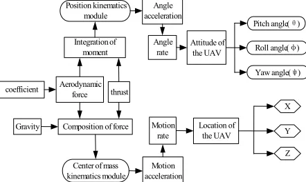
we also can add wind disturb and turbulence into in air- craft reference frame, which are adopted to compute the parameters of flight track. The angle rate in an aircraft reference frame can be resolved and transformed into the ground reference frame, then attack angle and sideslip angle and their transformation ratio can be calculated, which would offer to aerodynamic module. The angle could be decompounded in ground reference frame and 3 Euler angles can be gained by integral, the computing results could offer attitude parameters to system. UAV 6 degrees of freedom (DOF) calculation flowchart is sh-
own as Figure 2. In the paper, we adopt modularization
method, aerodynamic module is one of the modules in the simulation system, when the structure of the airplane is changed, we can rebuild the aerodynamic force module, others module is unchanged.
3.1. Aerodynamic Characteristic of UAV
In the paper, study on a certain UAV which belongs to middle or miniature type. Its mass is less than 400 kilo-
grams, the wingspan is about 7 m, the wing area is 4m2,
flight height is less than 5000 m, and the precise of the simulation system is according to different purpose. The complexity of mathematics model is different because the different simulation purpose. The flight height and speed is not higher in the project. So according to struc- ture parameters and experimental purpose, using airplane dynamic simulation model in training simulator, we can make the assumption as below:
1) The airplane is rigid body, so we can neglect the elasticity effect on the body.
2) Mass and CG (center of mass) is constant.
3) Earth is inertia coordinate and assumed geography coordinate is inertial coordinate;
4) Neglect curvature of the earth.
5) Gravity is constant, as the UAV is flying altitude is not higher.
6) Assumed the OX axis and axis is in the
symmetry plane of coordinate, therefore .
OY
0
XZ yz
I I
Integration of moment Position kinematics
module
Composition of force Gravity
coefficient Aerodynamic force thrust
Center of mass kinematics module
Angle acceleration
Angle rate
Motion acceleration
Motion rate
Attitude of the UAV
Location of the UAV
X
Y
Z Pitch angle(θ)
Roll angle(φ)
Yaw angle(ψ)
[image:2.595.66.282.595.719.2]3.2. Characteristic Analysis of UAV
3.2.1. Dynamic Equation
The forces of UAV in the air include gravity, aerody- namic force and thrust force by the engine. It is shown that established vector equation in the reference of air- craft is the simple and convenient Aircraft coordinate is a dynamic coordinate, it have displacement moment and rotating moment, the moment equation in aircraft coor- dinate is expressed as follows.
d d
V V
V
t t
(1)
d d
V
t represents absolute derivative of vector V in ground
coordinate. V
t
represents relative derivative of vector V
in aircraft coordinates.
Its matrix expression is as follows:
0 0
x y z z y
t t
y z x x z a g
z x y y x
V V V X
V V V C Y C
V V V Z
g
(2)
t a
C represents transfer matrix from velocity coordi-
nate to aircraft coordinate.
t g
C represents matrix from ground coordinate to air-
craft coordinate. , ,
X Y Z are aerodynamic forces of drag, lift and side force in rate reference frame.
The UAV can receive the moment in the air mostly in- cludes aerodynamic moment, control moment, crossed moment, damp, etc.
It is shown that aircraft rotary equation, which sur- round the center of mass is most simply and convenient for analysis. It is assumed that aircraft coordinate is dy-
namic coordinate, its rotating angular rate is , it can
be calculated through (3). d
d
H H
H
t t
(3)
Its matrix expression is shown as (4),
1
st c d j
p
q I M M M M
r
(4)
In Equation (4), I is rotating inertia moment, Mst Mc
Md Mjare aerodynamic moment, control moment, damp
moment and crossed moment. Projection of Mc, Md, Mj in
aircraft coordinate together with Mst are consisted of
multiple moment.
3.2.2. Kinematics Equation
The kinematics equation for the centroid of UAV is
shown as (5),
x X
g
Y a
Z
y
z v V
V C v
V v
(5)
g a
C represents transfer matrix from rate coordinate to
ground coordinates
Rotating equation of UAV moved around centroid, an- gular rate of rotating of UAV is established which is rela- tive to ground coordinate [4].
tan sin cos
d d
d d cos sin
d d sin cos cos
xb yb zb
yb zb
yb zb
t t t
(6)
, ,
xb yb zb
represent component of the flight angu- lar rate in aircraft coordinate, respectively, the angular
rate is determined by attitude angle’s rate d dt,
d d , t d d t, d dt is along zg axis, d d t is
along y axis and d d t is along x axis.
Through related analysis we can simply the 6 degrees of freedom mathematics model for UAV, in order to keep
the precise result we should keep the airspeed and
attack angle
V
of UAV in linear region, which will
keep facticity and reliability of the simulation.
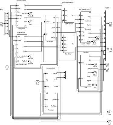
3.3. Dynamic Modeling Based on Simulink
Simulink is a powerful toolbox for dynamic modeling. It has many advantages such as strong computing ability, the simpleness of the program, abundant repeating model, which can transform code in real time with high effi- ciency. It has an abundant toolbox about engineering, includes aerospace tool which is adopted in aircraft mod- eling and simulation. Simulink adopts module design method, which is very convenient and intuitionist to con- struct a dynamic model, Aerosim is a whole 6 degree of freedom modeling toolbox which is developed from the Unmanned Dynamics company in the Simulink envi- ronment [5-7]. Using these modules we can construct the simulation system, choose specific module which we need and then combine these modules according to dy- namic data flow. Many modules cannot be used directly, for example, atmosphere model module, and physical ge- ography model module and so on. UAV system inside
structure is shown as Figure 3.
4. Simulation Analysis
Solve equations of motion
Inputs Outputs
Aerodynamic Model
Earth Model Sum forces and moments
Atmosphere Model Propulsion Model
AConGnd 15
REarth
14 AGL 13 MSL
12
ECEF 11
Mass 10 EngCoeff
9
PropCoeff 8 AeroCoeff
7
Euler 6
Ang Acc 5 Mach
4
VelW 3 Sensors
2 States
1
Total Moment Faero Maero Fprop Mprop CGpos
Mcg Total Acceleration Faero
Fprop
Mass Acc
GA Propulsion System Control OutofFuel
p T
rho WindAxesVel RST
Fprop
Mprop
Omega
FuelFlow
EngCoeff
PropCoeff
Equations of Motion Accel Moment
Inertia Rearth
Gravity AConGnd RST
VelB Rates
Quaternions Position Groundspeed
DCM Euler Ang Acc
Earth Position
DCM MSL
AGL AConGnd Rearth
Requiv Gravity MagField
ECEF mu
Atmosphere MSL
AGL
Winds
VelB
VelW
DCM pstatic
OAT
rho
a
WindVel
WindRates Aircraft Inertia FuelFlow
RST Fuel
Mass
CGpos
Inertia
OutofFuel Aerodynamics
VelB WindB Rates WindRates AeroCon rho a
Faero Maero
AeroCoeff VelW Mach
pdyn
RST 3
Winds 2 Controls
[image:4.595.113.487.89.503.2]1
Figure 3. Module structure of the UAV system.
(includes aircraft dynamic, propulsion, wing span, iner- tial parameters, etc.). Running through this script at the Matlab command prompt, a new aircraft parameter file of the form filename.mat will be created [7-10]. If we cho- ose this file with. mat extension and fill it into the UAV parameters setting dialog box, we will accomplish pa- rameters configuration.
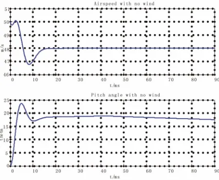
4.1. Simulation Example One
We make the assumption that the initial height of the UAV is 1000 m, initial speed is [50 0 0], rudder offset is
0 and the aircraft in ideal conditions (i.e., it flies under no
wind condition), add stabilization control loop Propor- tional-Integral-Differential (PID) control loop, we can see from simulation results that the airspeed is steady at 48 m/s with the setting value, in other word, it flies
steady with 48 m/s. pitch angle (theta) is steady at 17˚
with setting value just shown as Figure 4.
4.2. Simulation Example Two
We make the assumption that flight initial conditions of example 2 are nearly the same as example 1 and only add
wind vector [5 −5 0], i.e., add the lateral direction wind
in the simulation. As known that UAV could encounter much complicated weather conditions in its flying, and the variation of air current will affect flight attitudes of UAV. So the research under wind environment has its
practical meaning. In the simulation results in the Figure
5, it can be found that each flight parameter is instability.
Figure 4. Output results of airspeed and angle of pitch.
Figure 5. Output results of airspeed and angle of pitch.
5. Conclusion
In the paper we introduce the development tend and ap- plication fields of the simulation technology. We do the
research work of aeronautic simulation of UAV flight control based on characteristic and study on 6 degrees of freedom aerodynamic model. Modeling and simulation according to the certain type based on Simulink/Aerosim toolbox are performed; simulation is done under ideal condition and wind environment. We also present simu- lation curve of airspeed and pitch angle. The related re- sults show that the condition with wind is closer to actual condition, so our research work can offer the foundation for establishing UAV training simulator.
REFERENCES
[1] P. G. Fahlstrom and T. J. Gleason, “UAV System Intro- duction,” 2003.
[2] B. L. Stevens and F. L. Lewis, “Aircraft Control and Simulation,” 2nd Edition, Wiley, New York, 1992. [3] K. Nonmi, “Prospect and Recent Research & Develop-
ment for Civil Use of Autonomous Unmanned Aircraft as UAV and MAV,” Journal of system Design and Dynam- ics, Vol. 1, No. 2, 2007, pp. 120-128.
[4] N. Dai and Y.-L. Si, “Helicopter Flight Control System Modeling and Simulation by MATLAB,” Journal of Sys- tem Simulation, Vol. 18, No. 1, 2006, pp. 240-242.
[5] “Information on AeroSim Block User’s Guide.” http//: www.u-dynamics.com
[6] “Using SIMULINK,” Version 6.5, The MathWorks, Inc., Natic.
[7] B. Xu and Z. Liu, “Matlab Use in Engineering and Ma- thematics,” Tsinghua University Press, Beijing, 2000. [8] L.-N. Wu and Y.-M. Huang, “Multi-Mode State Flow,”
Journal of Hangzhou Dianzi University, Vol. 25, No. 4,
2005, pp. 34-37.
[9] B. Stevens and F. Lewis, “Aircraft Control and Simula- tion,” John Wiley & Sons, Inc., Hoboken, 1992.