© 2019, IRJET | Impact Factor value: 7.34 | ISO 9001:2008 Certified Journal
| Page 1575
PROGRSSIVE COLLAPSE ANALYSIS OF RCC STUCTURE FOR
VARIABLE HEIGHTS ON SLOPING GROUND
Prajakta Maruti Padule
1, Dr. Atul B Pujari
21
Post graduate student Department of civil engineering, KJ College of Engineering & Management Research,
Pune-28
2
Professor Department of civil engineering, KJ College of Engineering & Management Research, Pune-28
---***---Abstract -In recent years, the deficit of the plain ground to build commercial or residential structure in faster developing cities. Subsequently, construction of structure on hilly regions is increased day by day. Due to sloping profile, the various levels of such structures step back towards the hill slope and may also have setback at the same time. One of setback known as Progressive Collapse. Progressive collapse occurs when a structure undergoes a primary structural element fails, resulting in the failure of adjoining structural elements which in turns causes overall structural failure. A structure experiences progressive collapse when a primary structural member (generally column) fails due to explosion, vehicle impact, fire, manmade or natural causes. The failure of a member in the primary load resisting system, leads to redistribution of forces to the adjoining members and if redistributed load exceeds member capacity it fails. This process continues in the structure and eventually the building collapses. For present study the construction of structure on hilly region for analysis of progressive collapse potential of G+5, G+10 and G+15 concrete framed building assessed on sloping ground. When analyzing the structure on sloping ground the angles taken 0º, 20º, 30º for G+5, G+10 and G+15 building. Progressive collapse RCC structure G+5, G+10 and G+15 building is analyzes using the General Service Administration (GSA-2016) guidelines. To use Linear statics analysis method as per GSA (2016) guidelines for the axial force, bending moment, shear force, joint displacement of member and also to check on the basis of ETABS G+5, G+10 and G+15 building software and then also checked performance for Demand Capacity Ratio as per GSA (2016) guidelines.
Key Words: Progressive Collapse, RCC frame structure,
sloping ground, Linear Static Analysis, GSA 2016, ETABS
1. INTRODUCTION
Progressive collapse
Progressive collapse is a term now a days used worldwide. Progressive collapse phenomenon is initiated by the failure of one or more load carrying members. At the time of failure, to transfer excessive load, structural elements structure will seek alternate load paths. Sometimes structure may not be designed to resist additional loadings. Failure of overloaded structural elements will cause further redistribution of loading; this process will continue till the equilibrium is reached. When elements may reach equilibrium already a
large part of structure has already collapsed. The resulting overall damage may be disproportionate to the damage in the local region near the lost member. The hilly areas have marked effect on the buildings in terms of style, material and method of construction leading to popularity of multi-storied structures in hilly regions. Capacity assessment of the structural progressive collapse and progressive collapse design are based on structural progressive collapse analysis, analysis methods include linear static, nonlinear static, linear dynamic and nonlinear dynamic. The American Society of Civil Engineering (ASCE, 2005) is the only mainstream standard which addresses the issue of progressive collapse in some detail. The guidelines for progressive collapse resistant design are noticeable in US Government documents, General Service Administration (GSA, 2003) and Unified Facility Criteria (UFC, 2009). The GSA guidelines have provided a methodology to diminish the progressive collapse potential in structures based on Alternate Path Method (APM). It defines scenarios in which one of the building’s columns is removed and the damaged structure is analyzed to study the system responses. With the current scenario of increasing reasons for disaster like situation at industrial or residential workplace. The main objective of this study is to implement GSA guidelines for RCC structure in three dimensional, which are designed according to Indian standard codes to assess the vulnerability behavior. The procedure has been carried out is Linear Static according to the guidelines, and analyzed by using by finite element software Etabs. All the structures should be analyzed before the construction since there are many possibilities of failure. But what if the structure supposed to be constructed on hill like in northern and north eastern states of India. Since the slope varies there are many possibilities that during an earthquake, structure would collapse down from a hill. To make the structure which maintain its own stability under steep slope under earthquake.
2. LITERATURE REVIEW
G+10 storied building has been generated for symmetric and asymmetric case.
Harish K S1, Akash K2, Amith A P3, Asha S V4, Harish R. Olekar5 [2] the present study deals with analysis of multistoried building (G+4) on sloped ground. In hilly areas, the buildings are built on sloping grounds. When the hilly areas come to under seismic zones, these buildings area highly vulnerable to earthquakes. The study comprising of analysis of multistoried building (G+4) by considering gravity loads and seismic loads (response spectrum method used) and also includes slope stability analysis. The modeling has done by providing different elevations at foundation level and analysis of building has carried out by using finite element software such as ETABS. ETABS is a sophisticated and flexible to use, special purpose analysis such as gravity loads, earthquake analysis, P-δ analysis etc.
3. Objective
To calculate the progressive collapse potential of a 5-storey, 10-storey and 15-storey building as per GSA (2016) Guidelines. Linear static and linear dynamic (response spectrum analysis) analysis have been done.
Using GSA 2016 guidelines again analyzing the structure.
To check performance of structure, use the D.C.R, axial force shear force and bending moment are considered.
Also, check the structural performance on sloping ground.
Study the progressive collapse of the RC building by looking into history of building collapses.
4. Guidelines by the U.S. General Services Administration (GSA)
To determine the potential of progressive collapse for a “typical” and “atypical” structure, designers can perform structural analyses. The following analysis case should be considered:
1. An exterior column near the middle of the long side of the building.
2. An exterior column near the middle of the short side of the building.
3. A column located at the corner of the building.
4. A column interior to the perimeter column lines for facilities that have underground parking and/or uncontrolled public ground floor areas.
5. METHODOLOGY
5.1 Linear Static Analysis
In the linear static analysis column is removed from the location being considered and linear static analysis with the gravity load imposed on the structure has been carried out.
From the analysis results demand at critical locations are obtained and from the original seismically designed section the capacity of the member is determined. Check for the DCR in each structural member is carried out. If the DCR of a member exceeds the acceptance criteria, the member is considered as failed. The demand capacity ratio calculated from linear static procedure helps to determine the potential for progressive collapse of building.
5.2Analysis Loading
For static analysis purpose the following vertical load shall be applied downward to the structure under investigation:
Load = 2(DL + 0.25 LL)
Where, DL = Dead Load
LL = Live Load
5.3 Acceptance Criteria
An examination of the linear elastic analysis results shall be performed to identify the magnitude and distribution of potential demands on both Symmetrical and unsymmetrical structural elements for quantifying potential collapse areas. The magnitude and distribution of these demands will be indicated by
Demand Capacity Ratios (DCR).
D.C.R. = QUD / QCE
QUD = Acting Force (demand) determined in component or connection/joint (moment, axial force, shear, and possible combine forces)
QCE = Expected ultimate, unfactored capacity of the component and/or connection/joint (moment, axial force, shear, and possible combine forces)
Using the DCR criteria of the linear elastic approach, structural elements and connections that have DCR values that exceed the following allowable values are considered to be collapsed.
The allowable DCR values for Symmetrical and unsymmetrical structural elements are:
DCR < 2.0 for Symmetrical structural configuration. DCR < 2.0 for Unsymmetrical structural configuration.
5.4 Model Description
© 2019, IRJET | Impact Factor value: 7.34 | ISO 9001:2008 Certified Journal
| Page 1577
beams. All the supports are modeled as fixed supports. Linear analysis is conducted on each of these models.
Load considered are as follows:
1. Dead Load as per IS 875 (Part I).
2. Live Load IS 875 (Part II) On Roof 1.5 KN/m2 and on Floors 3.0 KN/m2
3. Wind Load as per IS 875 (Part III).
4. Self-weight of the Structural elements, Floor Finish =1.5 KN/m2.
[image:3.595.311.561.56.623.2]5. Seismic loading as per IS: 1893 (Part I): 2002. Zone – V, Zone factor = 0.36, Soil Type = Type –II, Medium Class. The characteristic compressive strength of concrete (fck) is 25 N/mm2 and yield strength of reinforcing steel (fy) is 415 N/mm2. Analysis and design of building for the loading is performed in the ETABS 9.7. Five storey building is designed for seismic loading in ETABS 9.7 according to the IS 456:2000.
Figure 1: Plan of the Building
Table 1: Building plan is selected for the study
Fig 2: G+5 model generated in Etab
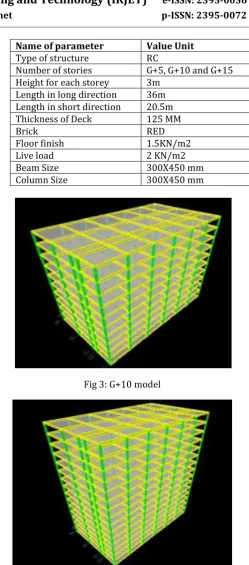
Fig 3: G+10 model
Fig 4: G+15 model
6. ANALYSIS AND RESULT
To evaluate the potential for progressive collapse of a five storey Unsymmetrical reinforced concrete building using the linear static analysis four column removal conditions is considered. First building is designed in ETABS v 9.7 for the IS 1893 (Part-I) load combinations. Then separate linear static analysis is performed for each case of column removal. Demand capacity ratio for the moments and forces at all storeys is calculated for four cases of column failure. Fig.5are
Name of parameter Value Unit
Type of structure RC
Number of stories G+5, G+10 and G+15 Height for each storey 3m
Length in long direction 36m Length in short direction 20.5m Thickness of Deck 125 MM
Brick RED
Floor finish 1.5KN/m2
Live load 2 KN/m2
Beam Size 300X450 mm
[image:3.595.50.273.361.525.2] [image:3.595.46.277.576.740.2]shown Column C1, C3, C8 and C32 are removed for progressive collapse analysis for each storey of building on sloping ground in different cases. Since DCR values obtained are within limit i.e. less than 2, so the progressive collapse
Fig 5: Location of column removal
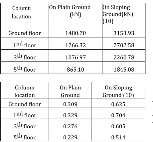
Table -2 & 3: DCR values and Axial load of corner column (C1) for G+5 storey.
In building structure, the displacement of storey are also considered for the plain ground and sloping ground.
Location Orginal 10 Degree 20 Degree 30 Degree Corner 43.124 42.95 41.26 39.649 Middle 91.557 91.482 91.045 90.775 Interior 98.978 98.98 96.266 99.266
Table -4: Storey displacement for G+5 building
Location Orginal 10 Degree 20 Degree 30 Degree Corner 46.136 48.434 47.582 44.571 Middle 99.326 98.555 98.349 100.869 Interior 101.383 106.715 103.271 106.259
Table -5: Storey displacement for G+10 building
Location Orginal 10 Degree 20 Degree 30 Degree Corner 43.458 49.05 48.505 44.826 Middle 97.623 96.924 96.838 100.691 Interior 95.425 104.751 101.28 127.509
Table -6: Storey displacement for G+15 building Storey Displacement
Variation of maximum storey displacement in X direction on plain and sloping ground
7. CONCLUSIONS
• After removal of particular column there is decreased in Axial and Banding moments of respective column.
•
• Bending Moments for adjust beams goes on increased and lead to failure (after Removal of column). From the analysis most critical column
The DCR values obtained for edge column exceeds the limit as per GSA guidelines, so the structure may fail for this fire load. It can be prevented by using larger steel sections or by increasing bracings.
As per the GSA guidelines, analyze for the instantaneous loss of a column located at or near the middle of the short side of building. (Case I), the middle of the long side of the building. (Case 2) and also loss of a column located at the corner of the building (Case 3).
References
1) A.A. Abolhassan, E.A. Madsen and C. Noble (2002), "Use of catenary cables to prevent progressive collapse Column
location
On Plain Ground (kN)
On Sloping Ground(kN) (10)
Ground floor 1480.70 3153.93
1nd floor 1266.32 2702.58
3th floor 1076.97 2260.78
5th floor 865.10 1845.08
Column location
On Plain Ground
On Sloping Ground (10)
Ground floor 0.309 0.625
1nd floor 0.329 0.704
3th floor 0.276 0.605
[image:4.595.35.292.363.602.2]© 2019, IRJET | Impact Factor value: 7.34 | ISO 9001:2008 Certified Journal
| Page 1579
of buildings,'" Tech. Report UCB/CEE-Steel-2001/02. Berkley: University of California. Department of Civil and Environmental Engineering, 2002.
2) D.J. Digesh, V. P. Paresh and J.T. Saumil (2010), "Linear and nonlinear static analysis'for assessment of progressive collapse potential of multistoried building," Structures Congress 2010, pp.3578-3589.
3) ETABS - 2016, "Integrated Building Design Software Manual"', CSI, USA.
4) Federal Emergency Management Agency (FEMA). 2002. World Trade Center Building Performance Study: Data Collection, Preliminary Observations, and Recommendations. FEMA 403 (USA), May 2002.
5) General Services Administration (GSA), (2003). "Progressive collapse analysis and design guidelines for new federal office buildings and major modernization projects". General Service Administration (USA)
6) Haberland, M., Starossek, U. (2009). "Progressive collapse nomenclature." Proceedings, ASCE SEI ,2009 Structures Congress, Austin, Texas, April 29May 2, 2009, pp.1886-1895.
7) IS: 875 (Part 1) - 1987, "Code of Practice for Design Loads (Other Than Earthquake) for Buildings and Structures - Dead Loads", Bureau of Indian Standards, New Delhi.
8) IS: 875 (Part 2) - 1987, "Code of Practice for Design Loads (Other Than Earthquake) for Buildings and Structures -Imposed Loads", Bureau of Indian Standards, Mew Delhi.
9) IS: 13920- 1993, "Indian Standard Code of Practice for Ductile Detailing of Reinforced Concrete Structures Subjected to Seismic Forces", Bureau of Indian Standards, New Delhi.
10)IS: 456-2000, "Plain and Reinforced Concrete-Code of Practice"', Bureau of Indian Standard, New Delhi, India.