Cite as: J. Appl. Phys. 126, 153104 (2019); https://doi.org/10.1063/1.5120025
Submitted: 16 July 2019 . Accepted: 27 September 2019 . Published Online: 21 October 2019
A. Klimont, A. Ottomaniello, R. Degl’Innocenti , L. Masini, F. Bianco, Y. Wu, Y. D. Shah , Y. Ren, D. S. Jessop, A. Tredicucci , H. E. Beere, and D. A. Ritchie
COLLECTIONS
Line-defect photonic crystal terahertz quantum
cascade laser
Cite as: J. Appl. Phys.126, 153104 (2019);doi: 10.1063/1.5120025
View Online Export Citation CrossMark Submitted: 16 July 2019 · Accepted: 27 September 2019 ·
Published Online: 21 October 2019
A. Klimont,1A. Ottomaniello,2,3R. Degl’Innocenti,4,a) L. Masini,2F. Bianco,2Y. Wu,1Y. D. Shah,1,5 Y. Ren,1,6 D. S. Jessop,1A. Tredicucci,2,3 H. E. Beere,1and D. A. Ritchie1
AFFILIATIONS
1Cavendish Laboratory, University of Cambridge, J. J. Thomson Avenue, Cambridge CB3 0HE, United Kingdom 2NEST, Istituto Nanoscienze-CNR and Scuola Normale Superiore, Piazza San Silvestro 12, 56127 Pisa, Italy 3Dipartimento di Fisica, Università di Pisa, Largo Pontecorvo 3, 56127 Pisa, Italy
4Department of Engineering, University of Lancaster, Bailrigg, Lancaster LA1 4YW, United Kingdom 5School of Physics and Astronomy, University of Glasgow, Glasgow G12 8SU, United Kingdom 6Purple Mountain Observatory, Chinese Academy of Sciences, Nanjing 210008, China
a)Electronic mail:r.deglinnocenti@lancaster.ac.uk
ABSTRACT
The terahertz (THz) quantum cascade laser (QCL) provides a versatile tool in a plethora of applications ranging from spectroscopy to astronomy and communications. In many of thesefields, compactness, single mode frequency emission, and low threshold are highly desir-able. The proposed approach, based on line defects in a photonic crystal (PhC) matrix, addresses all these features while offering unprece-dented capabilities in terms offlexibility, light waveguiding, and emission directionality. Nine line-defect QCLs were realized in a triangular lattice of pillars fabricated in the laser active region (AR), centered around∼2 THz by tuning the photonic design. A maximal 36% threshold reduction was recorded for these ultraflat dispersion line-defect QCLs in comparison to standard metal-metal QCL. The mode selectivity is an intrinsic property of the chosen fabrication design and has been achieved by lithographically scaling the dimension of the defect pillars and by acting on the PhC parameters in order to match the AR emission bandwidth. The measured line-defect QCLs emitted preferentially in the single frequency mode in the propagation direction throughout the entire dynamic range. An integrated active platform with multiple directional outputs was also fabricated as proof-of-principle to demonstrate the potential of this approach. The presented results pave the way for integrated circuitry operating in the THz regime and for fundamental studies on microcavity lasers.
© 2019 Author(s). All article content, except where otherwise noted, is licensed under a Creative Commons Attribution (CC BY) license (http://creativecommons.org/licenses/by/4.0/).https://doi.org/10.1063/1.5120025
I. INTRODUCTION
Quantum cascade lasers (QCLs) are well-established, compact semiconductor sources of coherent infrared and terahertz (THz) radiation. The fact that the vibrational and rotational resonances in many molecules lie in the THz region makes QCLs very attractive devices for applications in imaging,1 spectroscopy, and sensing.2 In all these applications, a well-defined single frequency mode of operation is an important, when not mandatory, requirement. The typical THz QCL emission exhibits a Fabry–Pérot multimode lasing spectrum over a ∼200 GHz bandwidth. Traditionally, the single mode operation has been achieved by engineering frequency selec-tive devices, such as distributed feedback resonators.3This concept
has been extended in two dimensions by implementing surface emitting photonic crystals (PhCs)4,5 for vertical emission and for in-plane emitters by placing photonic crystals in front of laser facets.6A popular and interesting approach to achieve light extrac-tion almost longitudinal to the laser cavity was reported by using a third order Bragg grating as the frequency selective element.7 Metasurface QCL VECSELs have been proved as an alternative viable route for shaping the beam emission.8The frequency selectiv-ity in these approaches normally increases the laser current thresh-old by introducing extra radiative channels.
as astronomy, where THz QCLs serve as local oscillators in hetero-dyne receivers in air-borne and space applications.9,10THz QCLs operating on theflat band edge of a PhC made of pillars etched in the active region (AR) were successfully demonstrated,11,12showing lasing over large areas and omnidirectional emission. Conversely, laser cavities based on line-defect waveguides (LDWs) are expected to present an ultralow lasing threshold,13 enriched frequency tunability, and unique features in terms of light directionality, e.g., virtually lossless bend waveguiding. For all the aforementioned features, photonic crystal waveguides have been proposed as the basis for an integrated THz platform comprising active and passive components for future terahertz communication systems.14–16This work is focused on LDW THz QCLs, fabricated by using similar techniques as reported in Refs.11and12. Differently, lasing occurs in the modes supported by the defects introduced in a PhC matrix. These devices exhibit single frequency emission and low current threshold density Jth compared to commensurate metal-metal (MM) QCLs of equivalent area that display multimode operations and are in agreement with previously reported THz PhC QCLs. The proposed LDW concept was extended to integrate QCLs in active photonic circuits. This is a unique and fundamental feature offered by this approach that cannot be reproduced in standard QCL ridges or omnidirectional PhCs. Finally, the line-defect (LD) architecture offers an excellent platform to study fundamental effects such as slow-light, Purcell enhancement,17or the investiga-tion of nonconveninvestiga-tional microcavity lasers.18,19
II. DESIGN OF LDWs IN PHOTONIC CRYSTAL QCLs
For THz QCLs, intersubband selection rules yield TM emitted light polarization. A lattice of high refractive index pillars in a low index medium gives rise preferentially to a TM photonic bandgap.20 A triangular lattice of pillars etched in the
[image:3.612.137.475.464.637.2]AR was chosen since it yields the widest possible bandgap.20 LDW QCLs were realized with 1 line, 3 lines, and 5 lines of regular pillars separating the defects, corresponding to the defect order D1, D3, and D5, respectively, as shown inFigs. 1(a)–1(c). The bandgap size depends on the refractive index contrast between the pillars and the surrounding medium and on ther/a ratio, where r is the pillars’ radius and a (|a1|=|a2|=|a|) is the lattice constant, as shown in Fig. 1(d). The refractive index nAR of the pillars is given by the active region material (GaAs/AlGaAs); all the calculations were performed assuming an effective index nAR= 3.6. The pillars are embedded in a low refractive index medium such as benzocyclobutene (BCB),19,21 which has a refractive index nBCB= 1.55. Figure 1(e) shows a typical LDW after the BCB planarization, before the evaporation of a metallic top layer for the electrical contact of the pillars. For these refrac-tive indices, the maximum achievable relarefrac-tive bandgap Δω/ω0is ∼0.3 at r/a= 0.25, where ω0 is the gap middle frequency. At a central frequency ofω0= 2π× 2 THz, this corresponds to an abso-lute gap width of 0.6 THz. The frequency range between 2 and 3 THz is particularly interesting for gas spectroscopy, as numerous molecules exhibit rotational and vibrational resonances in this frequency region. Bound-to-continuum QCL active regions are known to have low thresholds and, therefore, were chosen for this work. A bound-to-continuum design with the central fre-quency around 2 THz was used in this work because of the con-tinuous wave operation and low Jthof∼200 A cm−2(Ref.22) as well as material availability. However, this approach is fully com-patible with different ARs, and the photonic design can be scaled to match the emission at higher frequencies. Furthermore, this frequency range was chosen because of the less stringent fabrica-tion accuracy requirements. The gap middle frequency was engi-neered to be around 2 THz, by setting the lattice constantain the range of 42–46μm.
FIG. 1.Scanning electron microscope (SEM) pictures of the line defect QCLs after reactive ion etching for three different line-defect waveguides. Figure (a) corresponds to D1, where the defects before BCB planarization are separated by one row of small pillars in the triangular PhC lattice. Figure (b) (D3) and (c) (D5) correspond to line-defect QCLs separated by three rows andfive rows of small pillars, respectively. Figure (d) shows in more detail the defect area and identifies the main parameters of the PhC structure, such as the vectors on the direct triangular lattice,a1anda2, the radius of the regular and defect pillars,randR, respectively, as well as the line orientation.
III. OPTICAL MODES IN LDWs
Introducing a series of defects in the photonic lattice allows waveguiding, due to the conservation of crystal momentum. The modes supported by the defect are normally classified depending on the E-field nodes in the defect volume, e.g., a“dipole”mode exhibits two peaks of the E-field. Conventionally, a monopole mode is achieved for TM light in a rod lattice, by reducing the pillars’size. A reduction in the pillars’ radius would affect the AR volume, which is clearly an undesirable feature in the design of a laser struc-ture. However, because of the large bandgap achievable in these PhC lattices, defects with radius R>r can support higher order modes, including a degenerate monopole, having only one E-field maximum in a larger volume, suitable for lasing in a LDW. The photonic band structure of the triangular lattice as well as the defect modes were calculated with the MIT Photonic Bands software.23 Because of the total confinement provided by the metal-metal (MM) waveguide, the system was simulated considering only the emission plane in two dimensions. A supercell (SC) was used for the defect calculation that included a defect surrounded by four pillars with periodic boundary conditions. The results of the simula-tions are summarized inFig. 2for a lattice constanta= 44μm and r/aratio of 0.25. Because of the large bandgap achievable in these PhC systems, a defect with radius R > r supports four different modes in the range of 27–31μm, namely, dipole, quadrupole, monopole, and hexapole. The frequency dependence of these modes at different values of theR/aratio is reported inFig. 2(b)and their E-field distribution inFigs. 2(c)–2(f ). The“monopole”mode is in fact a superposition of higher order modes. The dipole and quadru-pole are degenerate due to the symmetry of the crystal. In order to quantify the energy concentration of the modes in the active mate-rial, the overlapΓ, defined in Eq.(1)as
Γ¼ Ð Ð
ARεjjEjj 2
Ð Ð
SCεjjEjj
2, (1)
was calculated for the different modes supported by the large defect radius. The integral of the E-field norm |E| in the numera-tor is calculated over the pillars (AR, the active region), while the integration in the denominator is performed over the whole supercell, andϵ is the dielectric constant. The calculated Γ for the monopole is approximately 0.89, and for the closest other mode—hexapole—it is reduced to 0.7. Only these modes fall within the bandwidth of the active medium; therefore, it was assumed that only the monopole is the preferential emission mode. This mode exists only in a short range of defect radii fromR= 0.58a toR= 0.7a(larger radius defects would touch the surrounding small pillars), which correspond to 25.5μm and 31μm, respectively, for the chosen lattice constant ofa= 44μm.
IV. LDWs FABRICATION
LDW QCLs were fabricated from a bound-to-continuum active region emitting at 2 THz, with a gain bandwidth of∼100 GHz. It was wafer-bonded to a GaAs substrate, which was subsequently pol-ished and etched, as is done routinely for MM processing. A metallic mask was defined by means of optical photolithography, and layers
[image:4.612.321.552.97.427.2]of Ti/Au/Ni (10 nm/500 nm/100 nm) were thermally evaporated. Nickel served as a sacrificial layer for the reactive ion etching (RIE) process. Approximately 14 μm-tall pillars were etched using a JLS Designs RIE80 tool, using SiCl4:Ar process gases in 6:10 sccm pro-portion. The etch rate was 100 nm/min. The PhC matrix was then planarized with BCB by using techniques and procedures already described in Ref. 19. The BCB provides a robust and stable matrix with low THz absorption and an excellent compatibility with several thermal cycles. In order to clean the top of the pillars from BCB and obtain aflat BCB surface around the pillars, the polymer was etched FIG. 2. (a) Photonic structure of the line defect laser for the defect radius
R= 31μm, small pillar radius = 11μm, and lattice constant a= 44μm (r/a= 0.25). Solid lines represent the air and dielectric band edges. The dashed lines between them show the different modes allowed in the defect pillars. Inset: the yellow bracket spans the bandwidth of a reference MM device from the same active region. The brown bracket is shown at the measured emission fre-quency of one LDW QCL by taking into account the spectral resolution of 0.25 cm−1of the fast-Fourier spectrometer available, which is in good agree-ment with the calculation. (b) Frequency dependence of the defect modes on
R/a. The horizontal bands on top and bottom represent the air and dielectric bands, respectively. The right axis shows the absolute frequency for the chosen
down chemically in an O2:CHF3(30:20 sccm) atmosphere. Finally, the top Ti/Au (10/300 nm) contact was evaporated, and the lasers were cleaved and mounted on copper blocks for efficient heat extrac-tion and wire-bonded to allow the device biasing and electrical trans-port. The reported devices were 0.5 mm long and ∼0.2 mm wide. The LDWs have 12 rows of pillars on each side of the LD to ensure total light confinement. According to the simulations performed, 5 rows are sufficient to completely block light transmission in this PhC system. The outer three pillar rows were not covered by metallic top contact, thus reducing the possibility of shorting the device and pro-viding absorbing boundaries to prevent lateral mode lasing. A refer-ence MM laser was cleaved into a ridge of a comparable area of 1 mm × 85μm. A second MM laser with similar size was fabricated yielding consistent values of the threshold current density, spectral emission, and maximum operating temperature TMax.
V. LDWs CURRENT DENSITY THRESHOLD
The light-current-voltage (LIV) characteristics of all the QCLs were acquired with a Tydex Golay cell and a lock-in amplifier gated at 9 Hz, with QCLs typically pulsed at 100 kHz repetition rate and 30% duty cycle. The LIVs as well as the spectra of the QCLs showed in the paper were all acquired at 4 K.Figure 3shows the results for one representative D1 LDW device withr/a= 0.25 and R= 28.3μm compared to the reference MM QCL. The LDW light intensity curves show a narrower and more uniform dynamic range than those in MM devices. The calculation of the current density Jth in photonic crystal lasers is a nontrivial task. The standard method to calculate the current density takes into account the area of all the pillars covered by the top Ti/Au (“area” method). This approach is based on the assumption that the electrical transport is the same in all the pillars contacted, regardless of the overlap with the lasing optical mode. Alternatively, Jth can be calculated by aligning current-voltage (IV) curves of a PhC device with a MM reference laser (“IV” method). Following a procedure similar to that in Ref.11and already reported in Ref.19, the IV curves of the
[image:5.612.138.474.503.647.2]LDW and reference MM were aligned prethreshold. This method of threshold estimation is illustrated in Fig. 3(a): the MM and LDW data are plotted together, with these latter ones artificially shifted in order to match the prethreshold slopes of the two IV curves. This method yielded a current density threshold for the LDW of Jth∼180 A cm−2, as shown inFig. 3(a). Thisfigure is 23% lower than the reference MM device, where Jthwas calculated to be ∼235 A cm−2. The results are commensurate with thefirst method, i.e., area estimation, which for the same representative device yielded Jth of ∼130 A cm−2, corresponding to a 40% reduction compared to the MM reference. The maximum operating tempera-ture in LDW QCLs (TMaxdef∼60–65 K) was only slightly lower than that of the reference MM device (TMaxMM∼75 K), similar to the reduction reported in Ref.24. This effect was mainly attributed to the increased optical power density in the LDWs.25–27 It is worth stressing that the TMaxrecorded is compatible with this AR design, chosen because of the low threshold QCL design and the low emission frequency, which allows more relaxed lithographic definition of the pillars and gaps. However, the line-defect concept can be readily extended to higher TMaxQCLs. The LIV characteris-tics of nine line-defect QCLs, three for each line-defect order (D1-D3-D5), were acquired in order to further investigate the Jth reduction. The results of the calculated averaged Jth(IV method) are shown inFig. 3(b), yielding a positive correlation between the current density reduction and the line-defect order. The minimal averaged threshold current density recorded for the D5 line defect is ∼150 A cm−2, approximately a 36% reduction compared to standard MM QCLs, while the D1 line reported a 23% reduction. These values are consistent with the 17% reduction in the current density threshold reported in Ref. 11 and 15% in the hyperuni-form cavity THz QCLs demonstrated in Ref.19. A current density reduction was observed also in the microcavity design in Ref.18, but within the experimental precision of the measurements. Surface emitting PhC QCLs, as in Ref.24instead, offer a superior far-field emission, but to the expenses of a higher current density threshold compared to similar MM devices. The further reduction
FIG. 3.(a) Light-current-voltage comparison between a defect and a MM device. The dashed lines and the solid lines represent the voltage-current and the light-current characteristics, respectively. Threshold current density estimated with the IV method is 180 A cm−2, which is 23% lower than MM J
th. The light intensity is not showed to
scale, for clarity. (b) Current densities for D1-D3-D5 QCLs compared to a MM one. Each line-defect Jthis averaged over three distinct lasers, showing a decreasing trend
in the higher line-defect order is consistent with the theoretical framework developed in Ref.28to describe line-defect resonators. The reduction in current density threshold is attributed mainly to two different mechanisms. Thefirst one is the strong modal confi -nement over volume comparable with the wavelength. The large radius defect pillar supports the monopole mode with higher overlap integral compared to other microcavity designs,29,30which typically showed emission frequency on whispering gallery modes. Furthermore, the PhC matrix around the defects provides an (ideally) lossless scattering confinement. There is an extensive and acquired literature that links group velocity reduction with gain enhancement in LDWs.25–27,31–34 The group velocity vg of the light propagating in the defect pillars is proportional to the cou-pling strength to adjacent defect cavities. A reduction in vgwould increase the effective refractive index, thus leading to a higher electromagnetic field concentration and gain enhancement. Accordingly, Jth decreases proportionally to the group velocity; ultraflat dispersions are provided by higher order line-defect QCLs, which present lower current density thresholds. A correct quantification of this effect would require a more precise fabrica-tion, possibly with ICP-RIE instead of RIE for the pillars dry etching, since small imperfections are detrimental for the full achievement of ultraflat dispersion. Slow-light LDWs are known to be particularly susceptible to disorder,35–37 which limit the attainable reduction in vgand are difficult to be inserted in the theoretical predictions even for passive waveguides. Other possible mechanisms responsible for the current density threshold reduc-tion could be lower losses and Purcell enhancement. In-plane losses are reduced in PhC, as reported in Ref.11, because of the more favorable E-field distribution in the waveguide. The mono-pole mode is confined in a volume comparable to (λ/n)3, which might suggest a possible Purcell enhancement. However, the pro-posed approach is more consistent with LDWs rather than a single isolated microcavity. Therefore, the contribution arising from these latter two effects was considered marginal for this class of devices. Line-defect QCLs have a significantly lower effective lasing volume than ridge lasers—defect pillars are about 10% of the total device. QCLs emitting with high power levels, up to a few Watts, have been reported,38 and the proposed approach is fully compatible with any AR design. The inherent difficulties in precisely and reproducibly cleaving the end of the LDWs affected the far-field emission patterns as well as the output powers recorded, although a maximum care was devoted in avoiding the cleavage of the LDWs in correspondence to the defects. Despite this, the devices showed a reproducible current density threshold reduction and controlled emission, which, together with the
demonstration of a novel LDW THz active platform, are the main targets of this paper.
VI. LDWs SPECTRAL CHARACTERIZATION
[image:6.612.327.546.100.375.2]The frequency spectra shown inFig. 4for the MM and line-defect QCLs of Fig. 3(a) were acquired using Fourier Transform Infrared (FTIR) spectrometer (Bruker, model IFS66v/S) and a liquid helium cooled bolometer as detector. The spectra of all the 9 QCLs could not be acquired because of their low output power and of the limited sensitivity of the FTIR available for these measure-ments. The standard MM QCL presents a multimode spectrum due to the Fabry–Pérot modes supported by the cavity, while the FIG. 4. Spectra recorded at different bias for (a) MM QCL, showing multimode emission, and (b) the LDW QCL whose LIV is showed inFig. 3(a). In (b), the emission is single mode throughout all the laser dynamic range. The other fully characterized QCLs reported inTable Ishowed similar trends.
TABLE I.Measured properties of four different line-defect lasers and a reference MM device. Higher emission frequencies are consistent with lower defect radii.
Type R, r, a(μm) Jth(A cm−2) area Jth(A cm−2) IV Frequency (THz)
MM // 235 235 1.88–1.96 (multimode)
D1 28.3, 11, 44 130 180 1.97
D1 29.6, 11.5, 44 230 205 1.89
D5 28.3, 10.5, 46 135 160 1.92
[image:6.612.50.562.619.695.2]line-defect QCL is single mode throughout all the dynamic range. All the measured line-defect QCLs were single mode, as expected from simulations, except one D3 QCL. This latter device was designed to emit around 2 THz but showed dual frequency emis-sion around 1.88 THz and 1.91 THz. The frequency difference between the emitted modes,∼30 GHz, is consistent with the fre-quency difference between monopole and hexapole modes sup-ported by the LDW.
These discrepancies were attributed to the nonoptimal photo-lithography/etching fabrication process. Nevertheless, this laser
exhibited a reduced threshold, in agreement with the other 8 LDW QCLs, and the trend is shown inFig. 3(b). The performances of four fully characterized devices with different defect radii (R) and having different distances between defects (D) are reported inTable I. The LDW laser characteristics described inFigs. 3(a)and4(b)correspond to the first D1 QCL reported in Table I. Although the limited dynamic range and the number of fully characterized QCLs available prevented a comprehensive discussion on the frequency control, the measured LDW QCLs point out the potentialities in geometrically controlled frequency tunability. Indeed, tunable single mode emis-sion can be achieved by changing the defect radius, as it is demon-strated by the D1 QCLs reported inTable I, which were designed to emit in single frequency at 2 THz and 1.9 THz, in very good agree-ment with the measured emitted frequencies of 1.97 THz and 1.89 THz, respectively. The QCLs realized with a D5 line and reported in Table Iexemplified the introduction of a line defect as an additional frequency control element to engineer the emitted frequency on top of varying the r/aratio, as it is usually reported in the literature. The new features achieved in LDW QCLs can be expanded by designing on the same platform multiple defect lines, active and/or passive, capable of emitting and/or delivering light in different directions and at different frequencies.
VII. INTEGRATED THz ACTIVE PLATFORM
[image:7.612.61.291.105.238.2]The proposed approach can be further exploited beyond the traditional straight-line design of QCLs and allows the introduction of (nominally) lossless waveguide angles. In order to investigate FIG. 5. Schematic of the integrated active THz platform having multiple
[image:7.612.50.570.411.717.2]direc-tional outputs based on the line-defect approach.
further this concept and highlight its potential, a more complex integrated active platform was designed, as shown in Fig. 5. The basic device has the shape of a“T,”where the“front”and“back” outputs are realized with D5 lines having radiusRof 29.5μm and 31μm oriented along the Γ-M direction. The“side,” instead, is a D5 LDW oriented along theΓ-K direction with a defect radiusRof 27μm. The radius r and the lattice constanta for the T-devices have been kept fixed to 11μm and 44μm, respectively. The side defect radius has been designed to allow only the quadrupole mode around 1.92 THz within the AR bandwidth, having the lowest overlap integral. In the front branch (R= 29.5μm), only the mono-pole lies within the bandwidth of the AR at 1.96 THz. Finally, the
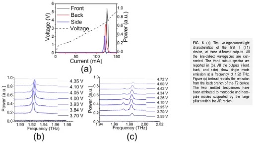
“back” branch (R= 31μm) was designed to accommodate two modes within the AR bandwidth, namely, the monopole at 1.93 THz and the hexapole at 1.955 THz. Two identical devices, namely T1 and T2, were fabricated according to the previously described procedure as for the straight defect line. The current density thresh-old values for the two devices were determined (IV method) to be 120 A cm−2and 130 A cm−2for T1 and T2, respectively, which is in good agreement with the results presented inTable I. The mea-sured LIV curves from the three different outputs for the T1 device are presented in Fig. 6(a). Since the three branches are all con-nected, the IV characteristics are identical within the experimental error. The power recorded from the three outputs has been normal-ized to the maximum value of the front output. The front output is almost twice as intense as the side output. The spectral charac-terization of the emission from the front branch is reported in Fig. 6(b). Surprisingly, the spectra from the other outputs (not reported here) revealed the same single mode emission, which was attributed to the monopole mode supported by the front branch. The second T device instead has similar LIV characteristics but quite different spectra, as shown inFig. 6(c). The power from the back output was more than 5 times larger than the output from the front branch. The spectral content of the three outputs showed similar features and presented dual frequency emission for some voltage bias. The two emitted modes are separated by approximately 13 GHz, consistent with the hexapole and monopole modes sup-ported by the back branch for this radius defect. It is interesting to notice the reproducible frequency-shift of the peak at 1.983 THz, ∼2 GHz. This feature was attributed to the interaction between the two modes and to a gain pulling effect,39or alternatively to a mod-ification of the refractive index due to the lower frequency mode. The side branch does not seem to contribute to any active mode in these T-lasers but instead acts as a passive waveguide. The difference between the two T-devices has to be ascribed to the different, intrin-sically difficult, cleaving of the laser facets.
VIII. CONCLUSIONS
In conclusion, a set of THz QCLs emitting around 2 THz was realized by creating line-defect waveguides in a triangular lattice of pillars. The proposed approach is based on larger radius defects, rather than conventional smaller radius defects used for waveguiding, thus profiting from a larger AR volume. The defects support a few modes, namely, monopole, hexapole, and quadrupole that can be lithographically tuned to match the AR emission bandwidth. The line-defect QCLs present some unique features compared to more
conventional PhC QCLs, such as increased frequency selection capa-bility and directionality, while retaining the typical low-threshold behavior of this kind of laser. Different QCLs were fabricated with a relative distance between the defects of 1, 3, and 5 lines of pillars to further investigate the origin of the low-threshold characteristics in these LDW lasers. The current density thresholds measured exhibit a clear reduction trend for higher order line defect, coherently with flatter dispersions yielding a maximum of 36% threshold reduction in comparison to standard MM QCLs. Finally, complex T-shaped integrated QCLs were fabricated by including multiple outputs in the same PhC matrix. The spectral content within these T-devices could be varied by lithographically acting on the defect and standard pillar radius and lattice constant without affecting the current density threshold. The controlled directionality, low threshold, versa-tility, and single frequency emission are essential features for the future miniaturization of these devices and their integration in active photonic platforms.
ACKNOWLEDGMENTS
H.E.B. and D.A.R. acknowledgefinancial support from the Engineering and Physical Sciences Research Council (EPSRC) under Grant No. EP/P021859/1. R.D. acknowledgesfinancial support from the EPSRC under Grant No. EP/S019383/1.
Additional data sets related to this publication are available from the Lancaster University data repository at https://doi.org/10. 17635/lancaster/researchdata/288.
REFERENCES
1Y. Ren, R. Wallis, D. S. Jessop, R. Degl’Innocenti, A. Klimont, H. E. Beere, and
D. A. Ritchie,“Fast terahertz imaging using a quantum cascade amplifier,”Appl. Phys. Lett.107, 011107 (2015).
2M. Tonouchi,“Cutting-edge terahertz technology,”Nat. Photonics1, 97–105
(2007).
3L. Mahler, R. Koehler, A. Tredicucci, F. Beltram, H. E. Beere, E. H. Linfield,
D. A. Ritchie, and A. G. Davies,“Single-mode operation of terahertz quantum cascade lasers with distributed feedback resonators,”Appl. Phys. Lett.84(26), 5446 (2004).
4R. Colombelli, K. Srinivasan, M. Troccoli, O. Painter, C. F. Gmachl, D. M. Tennant,
A. M. Sergent, D. L. Sivco, A. Y. Cho, and F. Capasso, “Quantum cascade surface-emitting photonic crystal laser,”Science302(5649), 1374–1377 (2003). 5O. P. Marshall, V. Apostolopoulos, J. R. Freeman, R. Rungsawang, H. E. Beere,
and D. A. Ritchie,“Surface-emitting photonic crystal terahertz quantum cascade lasers,”Appl. Phys. Lett.93, 171112 (2008).
6L. A. Dunbar, V. Moreau, R. Ferrini, R. Houdre, L. Sirigu, G. Scalari,
M. Giovannini, N. Hoyler, and J. Faist,“Design, fabrication and optical charac-terisation of quantum cascade lasers at terahertz frequencies using photonic crystal reflectors,”Opt. Express13(22), 8960–8968 (2005).
7M. I. Amanti, M. Fischer, G. Scalari, M. Beck, and J. Faist,“Low-divergence
single-mode terahertz quantum cascade laser,”Nat. Photonics3(10), 586–590
(2009).
8L. Xu, C. A. Curwen, D. Chen, J. L. Reno, T. Itoh, and B. S. Williams,
“Terahertz metasurface quantum-cascade VECSELs: Theory and performance,”
IEEE J. Sel. Top. Quantum Electron.23(6), 1–12 (2017).
9Y. Ren, D. J. Hayton, J. N. Hovenier, M. Cui, J. R. Gao, T. M. Klapwijk,
S. C. Shi, T.-Y. Kao, Q. Hu, and J. L. Reno,“Frequency and amplitude stabilized terahertz quantum cascade laser as local oscillator,” Appl. Phys. Lett. 101, 101111 (2012).
10H.-W. Hübers, S. G. Pavlov, A. D. Semenov, R. Koehler, L. Mahler,
cascade laser as local oscillator in a heterodyne receiver,”Opt. Express13(15), 5890–5896 (2005).
11H. Zhang, L. A. Dunbar, G. Scalari, R. Houdre, and J. Faist,“Terahertz
pho-tonic crystal quantum cascade lasers,”Opt. Express15(25), 16818–16827 (2007). 12A. Benz, C. Deutsch, G. Fasching, K. Unterrainer, A. M. Andrews, P. Klang,
W. Schrenk, and G. Strasser, “Active photonic crystal terahertz laser,” Opt. Express17(2), 941–946 (2009).
13A. Sugitatsua, T. Asano, and S. Noda,“Characterization of line-defect-waveguide
lasers in two-dimensional photonic-crystal slabs,” Appl. Phys. Lett. 84(26), 5395–5397 (2004).
14W. Withayachumnankul, M. Fujita, and T. Nagatsuma,“Integrated silicon
photonic crystals toward terahertz communications,” Adv. Opt. Mater. 6, 1800401 (2018).
15M. Yata, M. Fujita, and T. Nagatsuma, “Photonic-crystal diplexers for
terahertz-wave applications,”Opt. Express24(7), 7835–7849 (2016).
16S. M. Hanham, M. M. Ahmad, S. Lucyszyn, and N. Klein,“LED-switchable
high-Q packaged THz microbeam resonators,” IEEE Trans. Terahertz Sci. Technol.7(2), 199–208 (2017).
17C. Walther, G. Scalari, M. I. Amanti, M. Beck, and J. Faist,“Microcavity laser
oscillating in a circuit-based resonator,”Science327(5972), 1495–1497 (2010). 18A. Pitanti, L. Masini, L. Baldacci, M. S. Vitiello, R. Degl’Innocenti, H. Beere,
D. Ritchie, and A. Tredicucci,“Continuous wave laser operation of a dipole-antenna terahertz microresonator,”Light Sci. Appl.6(10), e17054 (2017).
19R. Degl’Innocenti, Y. D. Shah, L. Masini, A. Ronzani, A. Pitanti, Y. Ren,
D. S. Jessop, A. Tredicucci, H. E. Beere, and D. A. Ritchie,“Hyperuniform disor-dered terahertz quantum cascade laser,”Sci. Rep.6, 19325 (2016).
20J. D. Joannopoulos, S. G. Johnson, J. N. Winn, and R. D. Meade,Photonic
Crystals: Molding the Flow of Light, 2nd ed. (Princeton University Press, 2008).
21R. Degl’Innocenti, Y. D. Shah, R. Wallis, A. Klimont, Y. Ren, D. S. Jessop,
H. E. Beere, and D. A. Ritchie, “A hybrid plasmonic waveguide terahertz quantum cascade laser,”Appl. Phys. Lett.106, 082101 (2015).
22C. Worrall, J. Alton, M. Houghton, S. Barbieri, H. E. Beere, D. Ritchie, and
C. Sirtori,“Continuous wave operation of a superlattice quantum cascade laser emitting at 2 THz,”Opt. Express14(1), 171–181 (2006).
23S. G. Johnson and J. D. Joannopoulos,“Block-iterative frequency-domain methods
for Maxwell’s equations in a planewave basis,”Opt. Express8(3), 173–190 (2001). 24Y. Chassagneux, R. Colombelli, W. Maineult, S. Barbieri, H. E. Beere,
D. A. Ritchie, S. P. Khanna, E. H. Linfield, and A. G. Davies,“Electrically pumped photonic-crystal terahertz lasers controlled by boundary conditions,”Nature457, 174–178 (2009).
25T. Baba, “Slow light in photonic crystals,” Nat. Photonics 2, 465–473
(2008).
26H. Benisty, A. David, L. Martinelli, E. Viasnoff-Schwoob, C. Weisbuch,
G.-H. Duan, K. Janiak, and H. Heidrichet,“From modal control to spontaneous emission and gain in photonic crystal waveguides,” Photonics Nanostruct. Fundam. Appl.4, 1–11 (2006).
27T. F. Krauss,“Slow light in photonic crystal waveguides,” J. Phys. D Appl.
Phys.40, 2666–2670 (2007).
28A. Yariv, Y. Xu, R. K. Lee, and A. Scherer,“Coupled-resonator optical
wave-guide: A proposal and analysis,”Opt. Lett.24(11), 711–713 (1999).
29L. A. Dunbar, R. Houdré, G. Scalari, L. Sirigu, M. Giovannini, and J. Faist,
“Small optical volume terahertz emitting microdisk quantum cascade lasers,”
Appl. Phys. Lett.90, 141114 (2007).
30G. Fasching, V. Tamosiunas, A. Benz, A. Maxwell Andrews, K. Unterrainer,
R. Zobl, T. Roch, W. Schrenk, and G. Strasser, “Subwavelength microdisk and microring terahertz quantum-cascade lasers,”IEEE J. Quantum Electron.43(8), 687–697 (2007).
31S. Ek, P. Lunnemann, Y. Chen, E. Semenova, K. Yvind, and J. Mork,
“Slow-light-enhanced gain in active photonic crystal waveguides,” Nat. Commun.5, 5039 (2014).
32K. Sakoda,Optical Properties of Photonic Crystals, 2nd ed. (Springer, 2005). 33K. Kuroda, T. Sawada, T. Kuroda, K. Watanabe, and K. Sakoda, “Doubly
enhanced spontaneous emission due to increased photon density of states at photonic band edge frequencies,”Opt. Express17(15), 13168–13177 (2009). 34K. Kiyota, T. Kise, and N. Yokouchi,“Various low group velocity effects in
photonic crystal line defect waveguides and their demonstration by laser oscilla-tion,”Appl. Phys. Lett.88, 201904 (2006).
35T. Baba and D. Mori,“Slow light engineering in photonic crystals,”J. Phys. D
Appl. Phys.40, 2659–2665 (2007).
36C. Ferrari, F. Morichetti, and A. Melloni, “Disorder in coupled-resonator
optical waveguides,”J. Opt. Soc. Am. B26(4), 858–866 (2009).
37F. Morichetti, C. Ferrari, A. Canciamilla, and A. Melloni,“Thefirst decade of
coupled resonator optical waveguides: Bringing slow light to applications,”Laser Photon. Rev.6(1), 74–96 (2012).
38L. Li, L. Chen, J. Zhu, J. Freeman, P. Dean, A. Valavanis, A. G. Davies, and
E. H. Linfield,“Terahertz quantum cascade lasers with > 1 W output powers,”
Electron. Lett.50(4), 309–311 (2014).
39L. Schrottke, X. Lü, B. Röben, K. Biermann, M. Wienold, H. Richter,