INTRODUCTION
The requirements of modern aviation design necessitate the use of solutions, which until re-cently belonged to the group of load-bearing systems perceived by the aircraft construction regulations as failing to provide adequate safety guarantees. Typical examples of such solutions are composite thin-layered structures, based on a construction scheme deviating from the tradi-tional concept of multilayer sandwich construc-tion. If a layer preventing the cover from moving in normal direction to its surface is not used, the problem of buckling occurs.
In the case of metal support structures, af-ter years of attempts to prevent loss of stability through thin-layered coatings, for example, using flattened sheets, the admissibility of this phenom -enon in the local and elastic range has become widespread. This is due to a sufficient knowledge of the nature of physical phenomena occurring in
systems made of aluminum alloys and relevant knowledge on fatigue issues.
In the case of composite support structures, the principle of non-acceptance of the effects of loss of stability has been widely accepted, due to high degree of heterogeneity of construction of such structures and the associated probability of local damage, which could cause damage to the structure under cyclic loading conditions.
Increasing demands on the economics of air-craft use and the development of composite tech-nology, enabling high repeatability of the me-chanical properties of laminated structures to be obtained, will allow for certain derogations from the existing construction schemes – Boeing 787’s supporting structure is an example of this trend. It should be emphasized, however, that in this case the permissibility of the solution was conditioned by very stringent laminating technology require-ments and to carry out a suitable strength test pro-gramme for cyclic loads.
BUCKLING DEFORMATION OF THIN LAYER COVERINGS OF SMALL
CURVATURES USED IN AIRCRAFT CONSTRUCTION
Tomasz Kopecki1, Tomasz Lis1, Przemysław Mazurek1, Jerzy Bakunowicz2
1 Rzeszów University of Technology, The Faculty of Mechanical Engineering and Aeronautiucs, Al. Powstańców Warszawy 8, 35-959 Rzeszów, Poland, e-mail: tkopecki@prz.edu.pl, list@prz.edu.pl, pmazurek@prz.edu.pl 2 University of the West of England, Department of Engineering Design and Mathematics, Coldharbour Lane,
Stoke Gifford, Bristol BS16 1QY, United Kingdom, e-mail: Jerzy.Bakunowicz@uwe.ac.uk
Research Journal
Volume 12, Issue 1, March 2018, pages 293–302
DOI: 10.12913/22998624/85660 Research Article
ABSTRACT
This paper presents the results of experimental and numerical analysis in terms of the finite element method of plating components of aircraft load bearing structures. The subject matter of the study was composite panels with stiffeners in the form of a regular grid of oriented longitudinal elements in accordance with the directions of the principal stresses in the covering. The analysis was conducted in the buckling states of structural deformation which showed that structures with stiffeners exhibit much more favorable behavior in buckling deformation states than in laminar structures. This translates into stress distributions and their gradients, which are milder in forms of stiffened structures.
Keywords: buckling, isogrid, loss of stability; aircraft load-bearing structures; finite elements method; nonlinear numerical analysis
In general, the loss of stability of thin-lay-ered composite structures is still a problem and alternatives are still being sought for sandwich structures, which would reduce the weight of the construction while maintaining the required level of safety.
The problem of buckling of the cover con-cerns several elements of the airframe, in particu-lar particu-large areas of wings and fuselage (Fig. 1).
In the case of large aircraft structures intend-ed for the carriage of passengers and goods, the radii of the curvature of the coatings located in the areas under consideration are generally large enough that an isolated, small portion of the cov-ering can be treated as close to flat. The tendency for cyclical loss of stability of this kind of thin-walled system is primarily the result of twisting of the airframe components.
The results presented in this paper are a con-tinuation of research carried out by the authors in the field of experimental research and numeri -cal analysis of composite load-bearing structures with special attention to work on buckling defor-mation, whose details can be found in [10,11]. In this paper, the authors focused on the analysis of solutions based on integral isogrid stiffeners, made of GFRP composite with mechanical prop-erties similar to the propprop-erties of the composite used to make the cover. The basic assumption about the deformation of the examined structures was that the loss of stability, in contrast to the analogous metal constructions, in which only the local character within the elemental covering area is classified into the operating range.
Refer to Chapter 2 for a detailed description of the structure studied. The next two parts present the results of experimental research and numeri-cal analysis. Chapter 3 describes the course of the
experiment along with the results of optical de-formation measurements, which were compared in Chapter 4 with the results of FEM calculations. The work was summed up by the conclusions concerning the main aspects of numerical model-ing of structures of this class in the light of the convergence of the results with the experiment. Furthermore, directions for further research were also provided, focusing on large-size structures with a distinct curvature.
PURPOSE AND SCOPE OF THE STUDY
An incentive for aircraft designers to pre-vent loss of stability of composite coatings is the fear that the cyclical appearance of corrugations with relatively small curvature radii causes local stress levels far beyond the composite strength limit. The appearance of this type of concentra-tion even in a small area leads to local delami-nation, initiating the damage and then losing the structural carrying capacity in its entirety [13]. In the case of flat sections of the covering, the buckling phenomenon is generally abrupt, which additionally increases the probability of structural damage [1,3,4,6].
The main aim of the study, in the presented considerations, was to determine the form and the course of the deformation of the isolated frag-ment of the composite structure consisting of thin-walled, laminar coating, reinforced with a lightweight iso-grid structure [8,9]. As a bench-mark for the research conducted, a buckling de-formation of the reference structure, consisting solely of covering itself, was assumed, devoid of stiffeners. The task was carried out in two stages. An appropriate experiment was performed and an
effective way of numerical modeling of the ana -lyzed structures was developed, using MSC Soft-ware based on the finite element method.
The subject of the studies was two thin-lay-ered systems, modelling an isolated fragments of aircraft covering. In the first case, hereinafter referred to as the reference structure, no form of stiffeners was used. In the second, the covering was stiffened with the iso-grid structure. Dimen -sions of the models in both cases were identical. Details of the geometry and structure of the com -posite layers are shown in Figure 2.
The edges of the experimental models were reinforced with wooden slats in which rows of holes were repeated, enabling attachment to the experimental stand.
The thin-layered composite coating consisted of two layers of glass fabric, with a basis weight: 50 g/m2 and 163 g/m2. Interglass 02037 and 92110
symmetrical glass fabrics were used for the con-struction of the models. The matrix was a blend of nutritious epoxy resin MGS L285 / H286 of known mechanical properties, which correspond-ed to the measurcorrespond-ed constants for the compos-ite: E11=22000 MPa, E22=22000 MPa, ν12=0.11, G12=4600. Models were made by contact method, with a reinforcement factor of 50/50. Principal directions of orthotropy of the composite were oriented in accordance with diagonal directions of the examined structure models.
The iso-grid skeleton was made as a grid me-chanically separated from a composite panel con-taining five layers of Interglass 92110 (Fig. 2).
EXPERIMENTAL RESEARCH
The experimental stand was carried out as the steel structure, consisting of four rigid edg-ing, connected by means of flexible joints, in ac -cordance with the assumed load pattern (Fig. 3a). Models were attached to the loading structure using rows of screw bolts (Fig. 3b). The loading system was driven by a Zwick-Roell hydraulic cylinder. The load level was controlled by the load force control method.
Displacement measurements of reference points were made using a cylinder measuring sys-tem and mechanical clock micrometers. The de-formation field of the model was identified using the optical scanner.
[image:3.595.93.503.490.751.2]The basic relation between structural change and load increment is the so-called equilibrium path, which, in the case of systems with multiple degrees of freedom, is a hypersurface in state hy-perspace, being impossible to present in the form of a two-dimensional graph [5,7]. In practice, therefore, it is desirable to obtain a replacement characteristic, defining the relationship between the selected state parameter and a single control
parameter, which is a function of the load acting on the structure.
In the case described, the horizontal compo-nent of the displacement of the lower right corner of the examined system was as a representative component of the state (point A – Fig. 3a). The control parameter was the force acting on the structure at this corner. As a result, representative equilibrium paths were obtained (Fig. 4)
The loss of stability of the covering occurred at a relatively close relative value of the Pkr=130 N critical force for both models. The course of
[image:4.595.80.524.61.378.2]equi-librium paths for both objects exhibits a similar character, despite a significantly different form of loss of stability of covering. After loss of stabil-ity, the global stiffness of the system decreased to 41 and 38% respectively for the stiffened model and without stiffening. Both schemes with load values of approx. 4.5Pkr obtaining a new form of minimum energy of stiffness of 76 and 64% of the value before the loss of stability. At the maximum value of the load used in the experiment, the stiff -ness of the isogrid type showed stiff-ness of about 12% greater than the deprived stiffeners.
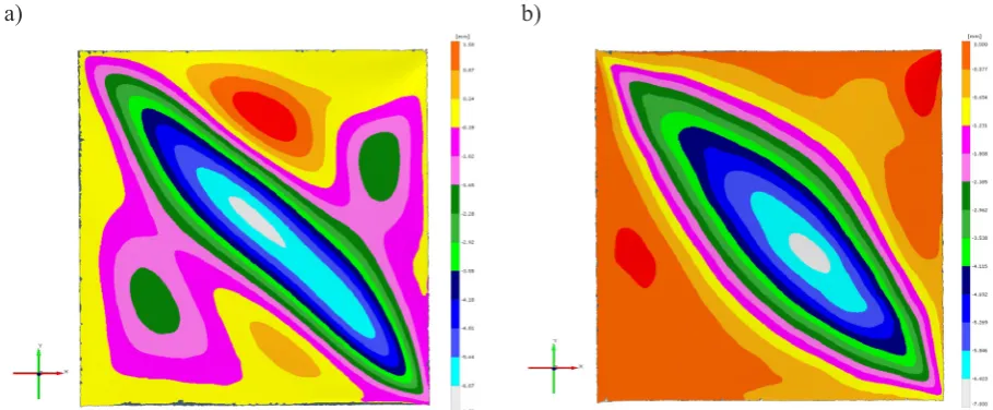
Figure 5 shows the deformation of the struc-ture of the deformed area in relation to the un-loaded system obtained with an optical scanner.
Attention varies in a form of stability loss. In the case of a coating without stiffness, apart from deformation on the main diagonal, the remaining significant areas of the model appear to have sig -nificant corrugation. Curvature of the folds in this case is significant and may be a potential cause of local structural damage under cyclic loading conditions. The stiffened model is characterized by a much more benign form of post-buckling de-formity. The dominant feature is the fold with a relatively large radius of curvature, running along the diagonal of the system.
Fig. 4. Representative equilibrium paths, determined during the experiment
a) b)
[image:4.595.73.288.597.740.2]The masses of the two bodies were also mea-sured. They were respectively as follows: 321g for the model without stiffeners and 361g for the model with stiffeners. Compared to the increase in stiffness for the post-buckling state, which is 6.5% for the reinforced structure, the weight gain of the structure is 12%.
NONLINEAR NUMERICAL ANALYSIS
The results of experimental studies were the basis for the development of adequate numerical models and their nonlinear analysis, using MSC PATRAN/MARC software, based on finite ele -ment method. The results of numerical analyzes were evaluated on the basis of satisfactory simi-larities between the nature of the deformation and the representative equilibrium paths, with respect to the results of the experiment. As a result, it be-came possible to determine stress distributions, based on the principle of unambiguous solutions, according to which, a given deformation structure corresponds to one and only one variant of stress distribution for a flexible system.
The experience gained by the authors in the area of nonlinear post-buckling analyses of thin-layer structures made of isotropic materials and composite panels [10,11] using this software, en-abled the development of numerical models of examined structures, which showed a satisfactory convergence of solutions. The key issue in nu-merical modeling of composite layers is the soft-ware component that defines laminate properties, based on sets of physical constants,
correspond-ing to each layer. In the case of used software, this algorithm is based on the classic theory of lami-nates, for which the mechanical properties of the composite (substitute material constants) result from a linear combination of anisotropic proper-ties of the specified thickness layers.
The issue that significantly impedes the prop -er reproduction of composite behavior in the nu-merical model is their heterogeneity, not only due to laminating conditions of individual layers, but also as a result of assembly operations, i.e. the presence of local resin overspill and the varied thickness of the glazing. These factors can result in local changes of shell rigidity and, as local im-perfections; they can have a significant influence on the form of post-bulking deformation. The numerical model, assuming, precludes faithful reproduction of the structure. Thus, even minor imperfections of real construction are actually er-rors in the selection of geometric parameters of the numerical model, what could be the source of the discrepancy between the results of the experi-ment and the numerical simulations.
The basic relationship in the nonlinear prob-lem, which defines the relationship between the state of the structure and the load, is the equilibri-um path of the system, which in the general case, as previously mentioned, is a hyper surface in hy-perspace state [2,12,14].This is a relation satisfy-ing the matrix residual forces equation:
𝑟𝑟(𝑢𝑢, Λ) = 0
(1)In which u is a state vector that contains the components of the displacement of the nodes of
[image:5.595.69.524.69.257.2]a) b)
the structure corresponding to its current geo-metric configuration, Λ is a matrix containing control parameters corresponding to the current load level, however r is the residual vector, con-taining unbalanced force components, related to the current deformation state of the system. The set of control parameters can be expressed by a single parameter, which is a function of load. Equation (1) then takes the following form:
r(u, λ) = 0
(2)called the monoparameric equation of residual forces.
Methods used in modern prognostic and cor-rection programs for determining further points of the equilibrium path also include the correction phase, based on the fulfillment by the comple -mentary equation system, called equation control or constrains equation [2,7,12]:
𝑐𝑐(Δ𝑢𝑢
𝑛𝑛, Δλ
n) = 0
(3)where the increase:
Δ𝑢𝑢
𝑛𝑛= 𝑢𝑢
𝑛𝑛+1− 𝑢𝑢
𝑛𝑛and
Δ𝜆𝜆
𝑛𝑛= 𝜆𝜆
𝑛𝑛+1− 𝜆𝜆
𝑛𝑛(4)
corresponding to the transition from the state n to the state n+1.
As in the case of the experiment, due to the lack of possibility to interpret the equilibrium path for systems with multiple degrees of free-dom in the form of a graph, in practice, represen-tative equilibrium paths are used for comparative purposes, constituting the relationship between the selected parameter, characterized by
deforma-tion of the system and a single control parameter associated with the load.
As confirmation of the reliability of the re -sults of non-linear numerical analyzes, there is satisfactory convergence between representative equilibrium paths: actual – determined during the experiment and obtained on a numerical basis. It is also essential similarity as deformation which constitute the calculation effect as a result of the experiment. Based on the principle of unambigu-ous solutions, simultaneunambigu-ously, effective stress distributions in the deformed system can also be considered credible [10].
In both cases, surface-solid models were used, treating the isolated coverage area as a sur-face and rigid periphery as solid objects. The ge-ometry of both models is shown in Figure 6.
Figure 7 shows finite element models. The fi -nite element mesh consisted of each model with about 14,000 nodes and about 12,000 elements.
Numerical analyses using the finite element method of perfectly flat thin-layer models, loaded only on its own plane, lead to the results char-acterized by this, the system does not achieve new deformation form, due to loss of stability of the covering, despite the critical load being ex-ceeded. This state of equilibrium is defined as a state of constant equilibrium, insufficient. Any sudden change of the equilibrium path from the primary, linear to secondary, nonlinear is only possible in the presence of additional imperfec-tions in numerical modeling, either geometric im-perfections, or the force acting perpendicular to the plane of the system. These imperfections are impulses that initiate bifurcation.
It is therefore necessary to include one of the named forms of initiation of post-critical
[image:6.595.69.527.574.747.2]defor-a) b)
mation in the numerical model. In the consid-ered cases, bifurcation initiation was achieved by means of concentrated forces, with values negli-gibly small in relation to the maximum load.
Nonlinear numerical analysis was based on the Newton-Raphson method, with control of the state. As a result of the analyzes, the distributions of displacements in advanced states of deforma-tion were obtained (Fig.8).
The deformation fields obtained by numerical calculations largely correspond to the analogous fields obtained in the experiment. They corre -spond both to the shape of the deformed surface and to the order of the values of lateral displace-ments. The results of numerical calculations show more regularity and axial or polar symmetry of corrugated cover. This is due to the idealization of the object as a numerical model, as mentioned earlier. Consequently, the size and nature of the deformation corresponds to the actual condition in a satisfactory manner and enables estimates of
the differences between the values of the corre -sponding stress distributions to be made.
The course of a representative equilibrium path was considered for the next criterion of con-vergence of the obtained numerical results with the results of the experiment. Similarly, as in the case of the experiment, this was the relationship between the horizontal displacement of the lower right corner and the value of the loading force. Figure 9 shows the summary graph of equilib-rium paths obtained in the experiment and nu-merical analysis for the model without stiffening and stiffeners.
Comparison of the equilibrium paths shows that the nature of their course is similar; however, as expected, the numerical models showed slight-ly higher stiffness then their actual prototypes, due to their idealized character. The relative dif-ferences in stiffness of the post-buckling model were not more than 15% in relation to the rigidity of the experimental model over the entire range
[image:7.595.77.525.68.248.2]a) b)
Fig. 7. Mesh of finite elements: a) model without stiffening, b) model with isogrid type stiffening
[image:7.595.66.526.576.746.2]a) b)
of the load being analyzed. Besides these differ -ences in the mapping of the imperfections of the real system, as another reason for increasing the rigidity of the numerical model, no satisfactory modeling of layers between laminate layers was found. Given that the covering used in the pre-sented designs was thin and the number of layers of fabric was small, the relative contribution of intermediate layers between laminate layers can be significant [1,4].
By confirming the satisfactory similarity of the distribution of displacement and the course of representative equilibrium paths by recognizing the principle of unambiguous solutions, it vali-dates the correct distribution of stresses obtained by numerical calculations. Figures 10 and 11 shows the distribution of effective stresses ob -tained by numerical calculations for the model without stiffening and with stiffeners.
By omitting the stress concentration areas as an undesirable numerical result, resulting from the perfectly focused nature of the forces
initial-izing bifurcation, as well as stress concentra-tions in the corners of the model, resulting from the specific boundary conditions adopted dur -ing the experiment, it can be stated that the na-ture of stress distribution resulting from the loss of stability of covering, in the case of a model with isogrid is uniform and devoid of concentra-tion, forming a potential cause of damage. In the case of a model without stiffening, significant concentrations occur in places corresponding to large curvature folds. Maximum stress levels are reduced by approx. 8% in the case of the model with stiffeners (Fig.10).
Significant differences also exist in the case of tangential stress distributions (Fig.11).
In the case of models without stiffeners, the highest stress values up to 60 MPa occur on a di-agonal of the model, in the area of the formation of the largest buckling deformation. In the case of an isogrid model, the tangential stress values do not exceed 40 MPa, are therefore more than 30% smaller than the model without stiffening.
SUMMARY AND CONCLUSIONS
The comparative analysis of two types of thin layered systems, corresponding to the sections of aircraft covering, leads to several key conclu-sions, the most important of which seems to state that despite the identical boundary conditions and geometrical similarities, the nature of buckling deformation of the structures under consideration is fundamentally different.
Increased stiffness of the isogrid stiffened structure, expressed as the horizontal component of the displacement of the selected corner,
ap-Fig. 9. Equilibrium paths obtained by means of ex-periments and numerical results
[image:8.595.73.288.69.215.2]a) b)
[image:8.595.75.525.579.748.2]proximately corresponds to the weight gain re-sulting from the application of stiffening, which apparently negates the reasonableness of using such solutions. It should be emphasized, howev-er, that the main purpose of applying any form of stiffening is not the overall increase in stiffness of the structure, but obtaining the features of the de-formation of the covering reduces the probability of damage to the composite structure. In a view of this assumption, the advantages of using the ana-lyzed form of stiffening appear to be significant.
In the case of non-stiffened covering, ad -vanced buckling deformations take a very un-favorable form, which is accompanied by high concentrations of stresses, in particular tangen-tial stresses. Under conditions of cyclic loading, such effects can result in local damage to the composite, which can be the beginning of the destruction process.
The use of spacers is a natural technology long used in aviation to avoid undesired large de-formation, however, even in this case, mild forms of loss of stability of cover segments are present, as far as they have a slight curvature.
Attempting to use stiffeners in a form of lightweight geodetic structure is a kind of indirect solution between the aforementioned. Although this is the case of the formation of buckling de-formation, this has a relatively mild form, which corresponds to stress distributions devoid of high concentration, with values substantially lower than in the case of the structure without stiffeners. This greatly reduces the likelihood of composite damage arising, while reducing the weight of the structure with respect to the spacer solution.
The last aspect that has not been analyzed in this paper is a collection of economic factors.
The cost of constructing an isogrid-like struc-ture is certainly higher than the use of a stan-dard spacer construction; however, it allows the weight of the fuselage to be lowered, thus con-tributing to improved performance and reduced fuel consumption.
Presented numerical models of examined structures, using solid elements for mapping of experimental stand components and surface ele-ments for mapping the coverage segment, based on the use of physical imperfections, in the form of forces of small values, allowing the correct calculation results, demonstrating satisfactory compliance with the results of the experiments. It must be emphasized, however, that nonlinear analysis is a multivalent method, and the quality of the results is determined by the correctness of the mapping of the boundary conditions and the application of the correct set of numerical meth-ods. Consequently, the results of the calculations should absolutely be verified by a suitable experi -ment, based on unverified results of nonlinear nu -merical analysis in design processes, leading to the formation of disqualifying structural defects.
DIRECTIONS FOR FURTHER RESEARCH
The experiments and numerical analyzes presented in this paper are the first of a series of studies on the properties of aircraft covering with small curvatures.
Another planned step is to map the fragment of the actual aviation structure into a suitably sized model and perform experiments using a test station adapted to high load applications (Fig. 12).
[image:9.595.67.526.69.241.2]a) b)
Creating a larger portion of the aerial
structure allows for accurate mapping of the
boundary conditions for any coverage
seg-ment and thus avoiding undesired distortions
of the results, as in the case of corner angles
of the presented structures.
It is also important to carry out model studies of selected fragments of composite aircraft struc-tures under cyclic loading conditions.
REFERENCES
1. Arborcz J, Post-buckling behavior of structures. Numerical techniques for more complicated struc-tures. Lecture Notes In Physics 1985; 288, 83–142. 2. Crisfield MA, Non-linear finite element analysis of
solid and structures, J. Wiley & Sons, 1997. 3. Doyle JF, Nonlinear analysis of thin-walled struc
-tures, Springer-Verlag, 2001.
4. Debski H, Sadowski T, Modelling of microcracks initiation and evolution along interfaces of the WC/ Co composite by the finite element method. Com -putational Materials Science 2014;83, 403–411. 5. Debski H, Teter A, Kubiak T: Numerical and ex
-perimental studies of compressed composite col-umns, Composite Structures 2014;118, 28–36. 6. Dobrzański P, Czarnocki P, Lorenz Z, Shell struc
-tures – theory and application, CRC Press, 2013. 7. Felippa CA, Crivelli LA, Haugen B, A survey of
the core-congruential formulation for nonlinear finite element, Archive of Computer Methods in Engineering 1994.
8. Huybrechts S, Tsai SW, Analysis and behavior of grid structures, Composites science and technol-ogy 1996; 56, 1001–1015.
9. Kim TD, Fabrication and testing of composite isogrid stifened cylinder, Composite Structures 1999; 45, 1–6.
10. Kopecki T, Numerical-experimental analysis of the post-buckling state of a segment multi-member thin-walled structure subjected to torsion, Journal of theoretical and applied mechanics 2011; 49(1), 227–242
11. Kopecki T, Bakunowicz J, Lis T, Post-critical de -formation states of composite thin-walled aircraft load-bearing structures, Journal of Theoretical and Applied Mechacnics 2016;54(1), 195–204. 12. Liang Huang, Sheikh A, Ching-Tai NG, Griffith
MC, An efficient finite element model for buck -ling analysis of grid stiffened laminated composite plates, Composite Structures 2015; 122, 41–50. 13. Lynch C. A. Finite element study of the post
buck-ling behavior of a typical aircraft fuselage panel, PhD Thesis, Queen’s University Belfast, 2000. 14. Riks E, An incremental approach to the solution
[image:10.595.158.437.70.280.2]of snapping and buckling problems, International Journal of Solid and Structures 1979; 15, 529–551.