A SUBBAND ADAPTIVE EQUALIZATION STRUCTURE
S. Weiss, D. Garc´ıa-Al´ıs, R.W. Stewart
Abstract
The potential presence of fractional delays, non-minimum phase parts, and a colouring of the channel output can require adaptive equalizers to adapt very long impulse responses. Besides resulting in a large computational complexity, this will in general cause slow convergence for LMS-type adaptive algorithms. In this paper, we address the equalization problem by a subband approach to reduce computational complexity and to improve convergence speed. We discuss, why amongst other possibilities of subband processing the oversampled approach is particularly appealing to significantly reduce computational complexity and improve convergence speed. Simulation results for a typical communication channels are presented and highlight the benefit of our method.
1. Introduction
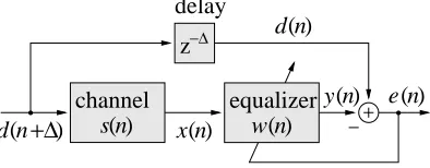
When data is transmitted through a channel, the characteristics of the channel generally create a signal distortion which may cause bit errors on the receiving side. Thus, in communication systems a filter is employed to equalize any linear distortions of the channel [11]. To account for time-varying behaviour of the system to be equalized, usually an adaptive solution is preferred. The general set-up of an adaptive equalizer is shown in Fig. 1:
+∆
−∆ z
equalizer
s n)(
channel y(n) e(n)
n)
(
d
n)
(
x
delay
n)
(
[image:1.595.195.392.307.384.2]w d n( )
Fig. 1: Adaptive equalizer set-up.
Here, the channel output x[n]is fed into the equalizerw[n]. After adaptation, the overall systems[n]w[n] should
ideally resemble a delay(n,)only. In a communications application,s[n]would incorporate any coding, modulation
/ demodulation, and transmission. For simplicity, we will assume linearity ofs[n].
Equalization is generally difficult due to a number of problems. Firstly, the system to be equalized may be of considerable length. Some mobile comms channels are modelled as impulse responses of up to 20 sec length, while the sampling
period is on a nanosecond timescale [16]. Similarly, equalizers for digital subscriber lines (ADSL) can require filters of more thanO(10
2
)taps [12]. Secondly, some types of characteristics are particularly hard to equalize, for example
minimum phase systems [10, 22], and fractional delays [7], which involve the identification of very long and generally non-causal impulse responses. For adaptive equalization operating in the fullband, adaptive algorithms with high computational complexity such as the RLS cannot be used, while for computationally less complex LMS-type algorithms the convergence speed depends on the filter length. Finally, if the channel exhibits large spectral dynamics, the filter input signalx[n]will
have a large eigenvalue spread and the convergence speed of LMS-type adaptive algorithms is further slowed down [5]. Therefore, the application of subband adaptive filters (SAF) appears sensible. In an SAF system as shown in Fig. 2, both input and desired signal,x[n]andd[n], are decomposed into decimated frequency bands. By operating adaptive filters
independetly in these subbands, both the update rate and the length of the adaptive filters can be greatly reduced leading to a lower computational complexity. Further, the subband decomposition performs a whitening of the input signal, resulting in improved convergence behaviour [6, 3].
In the following, we will give a brief introduction to subband adaptive filter structures, and concentrate on a particular SAF system using complex oversampled SAFs based on a signal decomposition using generalized DFT (GDFT) filter banks [1], which allows a very inexpensive implementation. Besides this, Sec. 2 also summarizes limiting influences in SAF systems. Sec. 3 discusses some fundamental problems of equalization and presents our approach to perform adaptive equalization in oversampled subbands. Finally, examples and results underlining the benefit of the proposed method are given in Sec. 4.
1
-1
0
-1
0
1
-1 0
1 x[n]
[n]
d
e[n]
filter bank
analysis
analysis filter bank
[ ]
x n
[ ]
x n
[ ]
x n
w w
filter bank
synthesis
d n[ ]
d n[ ]
d n[ ]
[ ]
e n[ ]
e n][
K
K
wK
1 0
-1
e n
[image:2.595.50.276.15.157.2]K
Fig. 2: SAF system with adaptive filters working inde-pendently inK decimated subbands; the subband
split-ting and fullband error reconstruction is performed by fil-ter banks.
synthesis filter bank
analysis filter bank
N
N
N
N
N
N
x[n]
x[n]
h [n]
0h [n]
1h
K- 1[n]
[image:2.595.310.534.62.157.2]g [n]
0g [n]
1g
K- 1[n]
Fig. 3: Decomposition of a signal x[n]by an analysis
bank intoKsubbands decimated byN K; a fullband
signalx [n]^ can be reconstructed by a synthesis bank.
2. Adaptive Filtering in Subbands
2.1 Structural Approaches to SAF
Subband adaptive filter (SAF) systems, as shown in Fig. 2, are widely used for problems such as acoustic echo cancellation (AEC), where a large number of adaptive parameters has to be adjusted and the adaptive filter input is coloured. Therefore general fullband adaptive systems are very costly to implement and show a considerable decrease in convergence speed. The reduction in complexity by the subband approach becomes viable due to decreased complexity by processing in decimated subbands. Furthermore, the separation into frequency bands can reduce spectral dynamics.
However, the case of critical decimation, where the decimation ratioNequals the number of uniform subbandsK, requires
either cross-terms at least between adjacent frequency bands [3], which compensate for the information loss in the region of spectral overlap, or gap filter banks [24, 14], which introduce spectral loss to avoid any aliasing problems. The drawbacks are, that the inclusion of cross-terms requires multichannel adaptive algorithms with generally slower convergences and again increased computational cost, while the distortion produced by gap-filter banks may not be acceptable.
Oversampled SAF systems, with a decimation ratioN <K, are designed such that after decimation the alias level within
the subbands is kept sufficiently low. Differences arise for the decimation of complex or real valued frequency bands. The decimation of real valued bandpass signals is generally complicated, and real valued signals have to be either modulated into the baseband prior to decimation by, for example, single sideband modulation (SSB,[1, 19]), or their bandwidth and decimation ratio has to be chosen in accordance with the sampling theorem, leading to non-uniform filter banks [13, 4]. In contrast, the decimation of complex valued bandpass signals with any integer factorN <Kis straightforward. Therefore,
we focus on an SAF system which generalized DFT (GDFT) filter banks [1], performing a particular type of complex valued subband decomposition. In general, complex valued filter banks can be shown to be at least as efficient to implement as their real valued counterparts.
2.2 Oversampled Modulated Filter Banks
A general structure of aKband filter bank with decimation by a factorN Kis shown in Fig. 3. The analysis filters
h
k
[n] are derived from a real valued lowpass prototype FIR filter p[n]of lengthL
p by a generalized discrete Fourier
transform (GDFT),
h
k [n]=e
j 2
K
(k +k0)(n+n0)
p[n]; k;n2N: (1)
The term generalized DFT [1] stems from offsetsk 0and
n
0introduced into the frequency and time indices. With k
0 =1=2,
for a real valued input signalx[n]it is sufficient to process the firstK =2subbands covering the frequency interval[0;]
as shown in Fig. 4, while the remaining subbands are redundant. Together with conditions onp[n], the time offsetn 0can
be set appropriately to ensure useful properties such as linear phase. The synthesis filtersg k
[n]can be obtained by time
reversion and complex conjugation of the analysis filters,
g
k [n]=h
k [L
p
,n+1] : (2)
0 0.2 0.4 0.6 0.8 1 1.2 1.4 1.6 1.8 2 −80
−60 −40 −20 0
normalized frequency Ω / π
20 log
10
|H
k
(e
j
[image:3.595.154.431.11.118.2]Ω )| / [dB]
Fig. 4: Example of aK=16modulated filter bank.
bank into a real valued polyphase network only depending on the prototype filter [2, 21]. The output of this network is rotated by a GDFT transform, which can be mainly implemented using an FFT.
Through the above modulation, the filter bank design reduces to an appropriate choice of the prototype filter, which has to fulfill two criteria. Firstly, the filter’s attenuation in the stopband, 2 [=N;], has to be sufficiently large. Every
frequency of the input signalx[n]lying within the interval[=N;]will be aliased into the baseband after filtering and
decimation, and cause a distortion of the subband signal. A second constraint on the design is the perfect reconstruction condition. If stopband attenuation of the prototype filter is high enough to sufficiently suppress aliasing, this condition reduces to the consideration of inaccuracies in power complementarity [17]:
K,1
X
k =0 jH
k (e
j
)j 2
!
=1: (3)
A prototype filter approximating these constraints can be constructed by an iterative least-squares method [19].
2.3 Subband Adaptive Filtering
When performing adaptive equalization in oversampled complex valued subbands, the adaptive filter lengths can be chosen shorter compare to a fullband adaptive filter in accordance with the sampling rate reduction by a factorN <K. Further,
updating now occurs at the lower rate. Following the approach in [19, 20], for real valued signalsx[n]andd[n]onlyK =2
complex subbands decimated byN <Kneed to be processed, since the remaining subbands are complex conjugate and
therefore redundant. This yields a reduction in computational complexity by a factorr= K
2N
2 for LMS-type algorithms
(omitting any additional costs introduced by the filter banks). Therefore, it is advantageous in terms of computational cost to keep the oversampling ratioK =N close to one, i.e. choose non-integer oversampling. For an extensive discussion of
computational costs, please refer to [21].
For an SAF system to perform satisfactorily, a delay in the path of the desired signal is required to account for various dec-imated transients of the analysis filter banks. If the SAF length is sufficient, no model truncation occurs, and if observation noise is absent, the minimum mean square error (MMSE) is limited only by the aliasing level produced by the decimation in the analysis filter banks, and the maximally achievable accuracy of the equalizer bound by the distortion function of the filter bank. In the case of modulated filter banks, both errors can be stated in terms of the prototype filter [20].
3. Subband Adaptive Equalization
For successful equalization, an adaptive algorithm is expected to perform an inverse system identification of the channel [22]. This becomes awkward as many real world channels are non-minimum phase systems, i.e. posses zeros outside the unit circle, e.g. in room acoustics [10] or communication systems [7]. Considering a maximum phase zero location a,
jaj>1, the inverse system can be stated by two representations for FIR equalizers, obtained by polynomial division:
(4)
1
1,az ,1
= 8
>
>
>
<
>
>
>
: 1
X
i=0 a
i
z ,i
,a ,1
z
1,a ,1
z =,
1
X
i=1 a
,i
z i
(5)
Although derived from the same left hand side, the expression (4) and (5) are fundamentally different: while (4) is causal but unstable, (5) is stable but non-causal. The two solutions are illustrated in Fig. 5. Only solution (5) is viable, and can be made partially causal by introducing a delay. If the zero positionais close to the unit circle, the impulse response of the
inverse system can become very long. Furthermore, the channels[n]generally colours the signalx[n].
w[n]
n stable, non-causal
[image:4.595.195.392.7.92.2]unstable, causal
Fig. 5: Two possibilities of representing an unstable pole by all-zero models.
[ ]n d
[ ]n e [ ]n
x
delay
interference
filters adaptive subband channel
analysis
analysis
synthesis
Fig. 6: Adaptive equalization in subbands.
non-causal part of the impulse response to be identified should therefore have approximately the same length.
4. Application Example
For simulation purpose, an artifical channel based on models (’Channel B’) in [16] is used to evaluate the benefit of the subband approach discussed in the previous sections. This channel represents a multipath environment with several echoes spread over a time interval of20sec. For a first evaluation, the amplitude of the reflections is assumed constants,
although ideally time-varying coefficients should be used to account for changes in the transmission medium. Sampling at a chip rate of 20MHz, the fact that some of the delays are not multiples of the sampling periodT
c
= 50nsec causes
the sampled channelc[n]to possess fractional delays. Looking at the instantaneous power of the channel,c[n]c
[n]
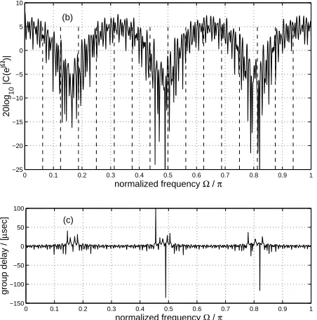
in Fig. 7, these fractional delays cause non-causal appearance and a leakage of energy from the actual delay values into neighbouring coefficients. The magnitude response and the group delay of the chosen system are shown in Fig. 7(b) and (c), respectively. This channelc[n]is to model all the transfer functions between transmitting and receiving the bit stream,
including any modulation and demodulation. Noise interference is added at the channel output at 25dB SNR. To obtain such a favourable SNR value, the use of an advanced modulation scheme (CDMA / QPSK) has been assumed.
−5 0 5 10 15 20 25
−70 −60 −50 −40 −30 −20 −10 0
time / [µsec]
10log
10
|c[n]|
2 / [dB]
[image:4.595.310.536.478.706.2](a)
Fig. 7: Channel characteristics: (a) power of the chan-nel’s impulse response, c[n]c
[n]; (b) magnitude
re-sponse and (c) group delay of the channel.
0 0.1 0.2 0.3 0.4 0.5 0.6 0.7 0.8 0.9 1
−25 −20 −15 −10 −5 0 5 10
normalized frequency Ω / π
20log
10
|C(e
j
Ω)|
(b)
0 0.1 0.2 0.3 0.4 0.5 0.6 0.7 0.8 0.9 1
−150 −100 −50 0 50 100
normalized frequency Ω / π
group delay / [
µ
sec]
[image:4.595.55.276.479.610.2]0 0.2 0.4 0.6 0.8 1 1.2 1.4 1.6 1.8 2 −25
−20 −15 −10 −5 0
time / [msec]
ensemble MSE / [dB]
(a)
0 0.2 0.4 0.6 0.8 1 1.2 1.4 1.6 1.8 2
−25 −20 −15 −10 −5 0
time / [msec]
ensemble MSE / [dB]
(b)
0 50 100 150 200 250 300 350 400
−25 −20 −15 −10 −5 0
time / [µsec]
ensemble MSE / [dB]
(c) subband (K=32,N=28)
[image:5.595.52.528.15.456.2]fullband
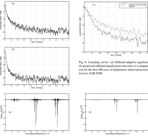
Fig. 8: Learning curves: (a) fullband adaptive equalizer; (b) proposed subband equalization structure; (c) compari-son for the first 400sec of adaptation; observation noise
level at 25dB SNR.
0 0.1 0.2 0.3 0.4 0.5 0.6 0.7 0.8 0.9 1
−25 −20 −15 −10 −5 0 5
normalized frequency Ω / π
20log
10
|S
f
(e
j
Ω)|
(a)
0 0.1 0.2 0.3 0.4 0.5 0.6 0.7 0.8 0.9 1
−25 −20 −15 −10 −5 0 5
normalized frequency Ω / π
20log
10
|S
s
(e
j
Ω)|
(b)
Fig. 9: Magnitude responses of overall systems consisting of channel and adapted (a) fullband and (b) SAF equalizer.
To invert the system characterized in Fig. 7(a)–(c), we apply an NLMS adaptive algorithm [?, 5] to a 3000 tap fullband equalizer. With a sampling period ofT
c
= 50nsec, this represents a length of 150sec. An SAF equalization system
withK =2=16complex subbands (with bandedges indicated by vertical dashed lines in Fig. 7(b)), decimated byN=28
requires(3000+896)=N 140tap filters in each channel. The increase in length byL p
= 896is to approximately
compensate for transients caused by the filter banks, which are modulated from a lowpass prototype withL
pcoefficients.
Both fullband and subband adaptive algorithms operate with the same normalized LMS step size of~=0:4[5]. From the
ensemble mean squared error curves in Fig. 8(a)-(c), an advantage in adaptation speed for the SAF equalization system is evident, while also requiring only approximately 10% of the computational resources of the fullband equalizer.
The magnitude responses of the overall equalized systemS(e j
) = C(e j
)W(e j
)are shown in Fig. 9. Within
this overall system,W(e j
)is the frequency response of the SAF system, which can be constructed from the subband
responses [21] after0:410 6
iterations (2 msec). The systemS f
(e j
)here refers to the overall system attained using the
fullband equalizer, andS s
(e j
)to the one including the SAF systems. The latter achieves a better inverse identification,
which is also indicated by the lower ’final’ MSE in Fig. 8(b) over the possibly still but very slowly converging fullband system. Obviously, both equalizers perform a reasonable equalization, but generally fail to provide a good inverse where the original channelC(e
j
)appears to exhibit spectral zeroes as indicated in Fig. 7(b).
[image:5.595.307.530.19.195.2]0 5 10 15 20 25 −1
−0.5 0 0.5 1
(a) transmitted signal
d[n+
∆
]
0 5 10 15 20 25
−2 0 2
(b) received signal
x[n]
75 80 85 90 95 100
−1 −0.5 0 0.5 1
(c) equalized signal
y[n]
[image:6.595.154.432.12.236.2]time / [µsec]
Fig. 10: Transmitted, received, and equalized bit stream: (a) d[n+]before undergong the channelc[n]; (b)x[n]at
the channel output; (c)y[n]at the output of the adapted SAF equalizer. Note the delays introduced throught the channel
(0:3sec), and the equalizer (75sec).
data has been accomplished. Any additional effort on further adapting the equalizer structure or choosing an equalization system with a much longer filter length would only add complexity, but most likely not add any further clearification of the received data.
Regarding SAF system parameters, the choice of the number of subbandsKforms a trade-off between the pre-whitening
effect of the subband approach and the number of band egdes introduced, which can lead to slower convergence [9]. Simulations in [21] indicate that the decimation ratioN has hardly any influence on the convergence speed, and should
therefore be choosen as close as possible toKto allow an inexpensive implementation.
5. Conclusions
We have introduced an oversampled subband adaptive filter approach to the equalization problem. We have motivated the application of subband adaptive filtering to the equalization problem, which can otherwise require a considerable filter length and suffer from slow convergence in a fullband implementation. The subband approach presented here used oversampled, near perfect reconstructing filter banks, which gives a significant reduction in computations and improved convergence speed over the fullband scheme.
The discussed method runs contrary to some approaches suggested in the literature, e.g. [15], which use oversampled adap-tive filters (fractional equalizers) to circumvent fractional delays and hence find better adaptable solutions for equalizers. In our method, the long impulse response required to model any fractional delay is reduced by applying adaptive filters to decimated subbands. In this context, “oversampled” here relates to the fact that the subbands are not critically decimated. However, decimation close to the critical rate is desirable to achieve inexpensive realizations.
Compared to a standard fullband adaptive equalizer, the presented method allows a considerably reduction in computa-tional complexity, while gaining in convergence speed. In general, if the channel exhibits stronger spectral dynamics than the one used in our example [16], the subband approach will provide a more pronounced increase in convergence speed over a fullband system [21].
The suitability of the introduced approach also depends on the tracking ability, which generally has characteristics different form the convergence speed [5]. While for applications such as equalization for telephone modems the transmission channel is generally assumed fixed, a wide range of mobile communcations systems exhibit time-varying channels. This property still remains to be evaluated for the SAF equalizer. Further, possible integration with the subband architecture found in transmultiplexers [23] may be investigated.
References
[2] Z. Cvetkovi´c and M. Vetterli. “Tight Weyl-Heisenberg Frames in l 2
(Z)”. IEEE Trans Signal Processing,
Vol.46(No.5):pp.1256–1259, May 1998.
[3] A. Gilloire and M. Vetterli. “Adaptive Filtering in Subbands with Critical Sampling: Analysis, Experiments and Applications to Acoustic Echo Cancelation”. IEEE Trans Signal Processing, Vol.SP-40(No.8):pp.1862–1875, Aug. 1992.
[4] M. Harteneck, J. M. P´aez-Borrallo, and R. W. Stewart. “An Oversampled Subband Adaptive Filter Without Cross Adaptive Filters”. Signal Processing, Vol.64(No.1):pp.93–101, January 1998.
[5] S. Haykin. Adaptive Filter Theory. Prentice Hall, Englewood Cliffs, 2nd edition, 1991.
[6] W. Kellermann. “Analysis and Design of Multirate Systems for Cancellation of Acoustical Echoes”. In Proc. IEEE
International Conference on Acoustics, Speech, and Signal Processing, volume 5, pages 2570–2573, New York,
1988.
[7] T. I. Laakso, V. V¨alim¨aki, M. Karjalainen, and U. K. Laine. “Splitting the Unit Delay”. IEEE Signal Processing
Magazine, Vol.13(No.1):pp.30–60, January 1996.
[8] M. Miyoshi and Y. Kaneda. “Inverse Filtering of Room Acoustics”. IEEE Trans Acoustics, Speech and Signal
Processing, Vol.36(No.2):pp.145–151, Feb. 1988.
[9] D. R. Morgan. “Slow Asymptotic Convergence of LMS Acoustic Echo Cancellers”. IEEE Trans on Speech and
Audio Processing, Vol.2(No.3):pp.126–136, March 1995.
[10] S. T. Neely and J. B. Allen. “Invertibility of a Room Impulse Response”. Journal of the Acoustic Society of America, Vol.66(No.1), July 1979.
[11] J. G. Proakis. “Channel Equalization”. In J. D. Gibson, editor, The Mobile Communications Handbook, chapter 6, pages 56–80. CRC Press / IEEE Press, 1996.
[12] M. Rude (ADC Telecommunications). Personal Communication, 1999.
[13] V. Somayazulu, S. Mitra, and J. Shynk. “Adaptive Line Enhancement Using Multirate Techniques”. In Proc. IEEE
Intern. Conf. Acoustics, Speech, and Signal Processing, volume 2, pages 928–931, Glasgow, Scotland, UK, May
1989.
[14] O. Tanrikulu, B. Baykal, A.G. Constantinides, and J. Chambers. “Residual Echo Signal in Critically Sampled Subband Acoustic Echo Cancellers Based on IIR and FIR Filter Banks”. IEEE Trans on Signal Processing,
Vol.45(No.4):pp.901–912, 1997.
[15] J.R. Treichler, I. Fijalkow, and C.R. Johnson. “Fractionally Spaced Equalizers”. IEEE Signal Proc. Magazine, Vol.13(No.3):pp65–81, May 1996.
[16] UMTS 30.03, version 3.1.0. ETSI Technical Report, 1997-11.
[17] P. P. Vaidyanathan. Multirate Systems and Filter Banks. Prentice Hall, Englewood Cliffs, 1993.
[18] S. Weiss, S. R. Dooley, R. W. Stewart, and A. K. Nandi. “Adaptive Equalization in Oversampled Subbands”.
Elec-tronics Letters, Vol.34(No.15):pp.1452–1453, July 1998.
[19] S. Weiss, L. Lampe, and R. W. Stewart. “Efficient Implementations of Complex and Real Valued Filter Banks for Comparative Subband Processing with an Application to Adaptive Filtering.”. In Proc. Intern. Symp. Communication
Systems and Digital Signal Processing, pages 32–35, Sheffield, UK, April 1998.
[20] S. Weiss, R.W. Stewart, A. Stenger, and R. Rabenstein. “Performance Limitations of Subband Adaptive Filters”. In
European Signal Processing Conference, volume III, pages 1245–1248, Rodos, Greece, September 1998.
[21] S. Weiss and R.W. Stewart. On Adaptive Filtering in Oversampled Subbands. Shaker Verlag, Aachen, Germany, 1998.
[22] B. Widrow and S. Stearns. Adaptive Signal Processing. Prentice Hall, Englewood Cliffs, New York, 1985.
[23] T. Wiegand and N. J. Fliege. “Equalizers for Transmultiplexers in Orthogonal Multiple Carrier Data Transmission”.
Annals of Telecommunications, Vol.52(No.1–2):pp.39–45, January 1997.
[24] Y. Yamada, H. Ochi, and H. Kiya. “A Subband Adaptive Filter Allowing Maximally Decimation”. IEEE Journal on


![Fig. 10: Transmitted, received, and equalized bit stream: (a)d[n+�] before undergong the channelc[n]; (b)x[n] atthe channel output; (c)y[n] at the output of the adapted SAF equalizer](https://thumb-us.123doks.com/thumbv2/123dok_us/1050499.620965/6.595.154.432.12.236/transmitted-received-equalized-undergong-channelc-channel-adapted-equalizer.webp)
