Abstract—In this paper, a revised version of the authors’
previously proposed power saving scheme for IEEE 802.16 is proposed to be applied in LTE. The proposed scheme namely LTE-LBPS-Aggr treats the traffic of all UEs as a single flow, estimates the input load by traffic measurement and the channel capacity by CQI reports, calculates the length of the sleep cycle, and notifies all UEs of the next radio-on time for receiving data. Simulation study shows that the proposed scheme outperforms the standard DRX mechanism in terms of the power saving efficiency and the delay performance.
Index Terms—LTE, DRX, Power Saving, LBPS
I. INTRODUCTION
ITH the increasing popularity of all sorts of mobile devices and Apps, modern life is being brought into a new era of mobile communications in recent years. To address the intense demand, the wireless technology for the
fourth generation (4G) [1] of mobile broadband
communications is standardized. 4G candidate systems including Mobile WiMAX [2] and LTE (Long Term Evolution) [3-4] are commercially deployed. LTE standard is defined and supported by all major players in the telecommunication industry and is backward compatible with GSM/UMTS cellular systems, which makes LTE deployment easier than Mobile WiMAX, giving LTE benefit over its competitors in 4G market.
Although based on GSM/EDGE and UMTS/HSPA network technologies, both the core network (Evolved Packet
Core, EPC) and the radio access (Evolved Universal Terrestrial Radio Access Network, E-UTRAN) in LTE are
fully packet-switched, rather than following the circuit-switched model of earlier systems. LTE is designed to work with a variety of different bandwidths and to deliver a peak data rate of 100 Mbps in the downlink and 50 Mbps in the uplink. The enhanced version of LTE, namely LTE-Advanced (LTE-A), is designed with advanced features to deliver a peak data rate of 1000 Mbps in the downlink, and 500 Mbps in the uplink. The specifications for LTE produced by the Third
Generation Partnership Project (3GPP) are organized into releases, each of which contains a stable and clearly defined
set of features. LTE was first introduced in Release 8 [3], and initial enhancements were included in Release 9. The extra capabilities required for LTE-A were specified in Release 10 [4]. As the specification of Release 11 of the LTE standards Manuscript received Dec. 08, 2013; revised Dec. 08, 2013. This work was supported in part by the National Science Council, Taiwan, under grant no. NSC 102-2221-E-260-013.
Chun-Chuan Yang is with Dept. of Computer Science and Information Engineering, National Chi Nan University, Taiwan (e-mail: [email protected]).
is approaching its completion, 3GPP is gradually moving its focus toward the next major step in the evolution of LTE (Release 12).
One of the major issues in mobile communications is power saving/management at the user side as well as at the network side. Power saving at the network side creates the benefit of energy cost reduction, but the user side is more critical since the user device is usually battery-powered and the length of the operational time in communications is always a main focus. Discontinuous Reception mode (DRX) [5-6] is supported to conserve the power of the mobile terminal namely the User Equipment (UE) in LTE. The UE powers down most of its circuitry in DRX when there are no packets to be transmitted or received. During this time, the UE listens to the downlink (DL) occasionally and may not keep in sync with uplink (UL) transmission depending on its
RRC (Radio Resource Control) state. There are additional
advantages in using DRX, such as radio link resource saving on both UL and DL to increase system capacity.
The authors have been working on the issue of power saving in IEEE 802.16 for some years. The idea of
Load-Based Power Saving (LBPS) and associated schemes were
proposed to adaptively schedule the sleep (radio off) time of the user device for the current network load [7]. Extension of LBPS to integrate the user side and the network side in sleep scheduling was also proposed [8]. In this paper, a revised scheme of LBPS applying to LTE DRX is proposed. Simulation study shows that the proposed scheme can adapt to the fluctuated system capacity as well as the input load and achieve high power saving efficiency. The remainder of the paper is organized as follows. In section II, a survey of the standard DRX in LTE, DRX related work, and our previous work of LBPS in IEEE 802.16 is presented in section II. Proposed LBPS scheme for LTE is presented in section III. Performance evaluation is presented in section IV. Finally, section V concludes this paper.
II. RELATED WORK
A. LTE DRX
In LTE DRX mode can be enabled in both of the states of the radio link between the UE and the base station (called
eNodeB or eNB): RRC_idle and RRC_connected. In the RRC_idle state, the UE is registered with the network but
does not have an active session, and the UE can be paged for Jeng-Yueng Chen is with Dept. of Information & Networking Technology, Hsiuping Univ. of Science & Technology, Taiwan (e-mail: [email protected], Corresponding author)
Yi-Ting Mai is with Dept. of Information & Networking Technology, Hsiuping Univ. of Science & Technology, Taiwan ([email protected]).
Ching-Hsiang Liang is with Dept. of Computer Science and Information Engineering, National Chi Nan University, Taiwan.
Design of a Load-based DRX Scheme for
Non-Real-Time Traffic in LTE
Chun-Chuan Yang,
*Jeng-Yueng Chen, Yi-Ting Mai, and Ching-Hsiang Liang
DL traffic. In the RRC_connected state DRX mode is enabled during the idle periods during the packet arrival process. When there are no outstanding packets to be transmitted or received, eNB or UE may initiate the DRX mode.
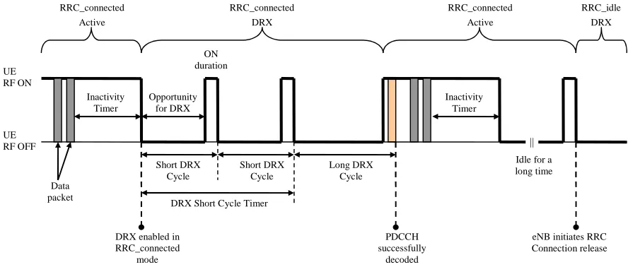
As illustrated in Figure 1, a DRX cycle consists of an “Opportunity for DRX period” (radio off) during which the UE can skip reception of DL channels and an “ON duration” (radio on) during which the UE should monitor the physical
downlink control channel (PDCCH) to identify DL data. The inactivity timer is used to trigger the start of a DRX cycle in
the RRC_connected state. The parameterization of the DRX cycle involves a trade-off between battery saving and latency. A long Opportunity for DRX period is beneficial for lengthening the UE’s battery life. On the other hand, a shorter DRX period is better for faster response. Therefore, two DRX cycles, namely Short DRX Cycle and Long DRX Cycle, can be configured for each UE. The transition between the Short
DRX Cycle and the Long DRX Cycle can be controlled by the DRX Short Cycle Timer or by explicit commands from eNB.
Analytical models for performance evaluation of the DRX operation in terms of power saving efficiency and transmission delay were proposed in the literature [9-10]. Heuristic mechanisms for adjusting the value of the inactivity timer based on CQI (Channel Quality Indicator) report was proposed in [11], in which higher CQI makes shorter inactivity timer for better system utility. Impact of the length of TTI (Time Transmission Interval) on power saving efficiency and access delay was investigated in [12]. Optimization of the two conflicting performance metrics, power saving and access delay, was addressed in [13-14].
B. Previous work of LBPS
The objective of LBPS is to adaptively adjust sleep window size of each MSS (Mobile Subscriber Station) to better fit in current traffic load by traffic measurement. The BS in LBPS needs to estimate the current load for each MSS (denoted by packets per time frame) by collecting and exponentially averaging the samples of load measure as in
TCP Round-Trip Time (RTT) estimation. For presentation
purpose, only downlink traffic is considered in this paper, although uplink traffic can also be integrated into LBPS schemes via some information exchange mechanism between the BS and MSSs. LBPS sets a target threshold of data accumulation in the buffer for an MSS and dynamically
calculates its next sleep window size. In this way, LBPS can adapt to different traffic loads and still achieves a proper level of powering saving. The basic version of LBPS, LBPS-Aggr, in which all the traffic in the network is treated as an aggregate flow in calculating the size of the sleep window. In
LBPS-Aggr, the traffic arrival process is assumed to be
Poisson, and data accumulation under load λ in a time frame is calculated by the following equation:
Prob [i packet arrivals in a time frame] =
! ) (
i T e−λT λ i ,
where T is the length of a time frame. The threshold of data accumulation is denoted by Data_TH (packets), which is practically set as the capacity of a time frame. The probability of data accumulation exceeding
Data_TH packets over K time frames in a row can be
calculated as follows:
PAcc(K, Data_TH) ≡
Prob [# of packet arrivals in K time frames > Data_TH]
=
∑
∞ + =−
1
_ !
) (
TH Data i
i KT
i KT
e λ
λ
=
∑
= − −Data TH
i
i KT
i KT e
_
0 !
) (
1
λ
λ
The number of time frames (including the current awake time frame) before the next awake time frame for an MSS is calculated as the smallest value of K such that PAcc(K,
Data_TH) is higher than a predefined probability threshold
denoted by Prob_TH. That is,
The length of one awake-and-sleep cycle
≡ LengthAwkSlpCyl (λ, Data_TH) ≡ K*
=
Min
{
K
|
P
Acc(
K
,
Data_TH
)
≥
Prob_TH
}
, where anawake-and-sleep cycle is composed of the current
awake time frame and the following sleep window. The size of the sleep window in a cycle is therefore K*-1, which is sent by the BS to the currently awake MSSs to prepare for entering the sleep mode.
UE RF OFF UE RF ON
RRC_connected Active
RRC_connected DRX
RRC_idle DRX
Data packet
Inactivity Timer
Opportunity for DRX
DRX enabled in RRC_connected
mode Short DRX
Cycle ON duration
Short DRX Cycle
DRX Short Cycle Timer
Long DRX Cycle
PDCCH successfully
decoded
Inactivity Timer RRC_connected
Active
|| Idle for a long time
[image:2.595.75.519.49.238.2]eNB initiates RRC Connection release
Improved mechanisms of LBPS-Aggr were also proposed in our previous work by elaborately grouping MSSs in sleep scheduling for better power saving efficiency, which are not surveyed in this paper since the proposed LBPS DRX scheme in LTE is mainly based on LBPS-Aggr.
III. LTE-LBPS
A. Basic idea
The previous work of LBPS-Aggr was designed for IEEE 802.16. Applying LBPS-Aggr to LTE requires proper addressing the features of LTE, which are discussed as follows:
(1)As illustrated in Figure 3, the basic time unit for packet scheduling and transmission in LTE is called a TTI (Transmission Time Interval) with length of 1ms. Thus, TTI is the time unit for LBPS to estimate the length of the sleep cycle in LTE. In each TTI, a scheduling decision is made where each scheduled UE is assigned a certain amount of radio resources in the time and frequency domain. In the time domain, a TTI is split into two 0.5ms slots. Each slot comprises 7 OFDM symbols in the case of the normal cyclic prefix length. In the frequency domain, resources are grouped in units of 12 subcarriers, such that one unit of 12 subcarriers for a duration of one slot is called a Resource Block (RB), which is the smallest element of resource allocation. The smallest unit of resource is the Resource Element (RE), which consists of one subcarrier for a duration of one OFDM symbol. Therefore, an RB is comprised of 84 (7x12) REs in the case of the normal cyclic prefix length.
(2)In order for LBPS to estimate the awake TTI in LTE for a given threshold of data accumulation (DATA_TH), it is necessary to estimate the current traffic load as well as the channel capacity. In our previous work, the channel capacity is assumed to be static, which should be revised for LTE. In LTE, eNB typically selects the modulation scheme and code rate depending on a prediction of the DL channel condition, which is according to the Channel
Quality Indicator (CQI) feedback transmitted by the UE.
[image:3.595.54.326.51.272.2]3GPP gives a table of reference for efficiency of each CQI index as shown in Table 1. The estimation of the channel capacity of LBPS in LTE is therefore based on the CQI report from the UE and the corresponding efficiency value in Table 1. Moreover, since LTE physical control channels (such as PDCCH, PCFICH, PHICH) also make use of the REs in the TTI, estimation of the capacity for the user data should exclude the REs reserved for the control channels.
Table 1. CQI table by 3GPP CQI
index Modulation
Approximate code rate
Efficiency (bits/RE)
0 No Tx -- --
1 QPSK 0.076 0.1523
2 QPSK 0.12 0.2344
3 QPSK 0.19 0.3770
4 QPSK 0.3 0.6016
5 QPSK 0.44 0.8770
6 QPSK 0.59 1.1758
7 16QAM 0.37 1.4766
8 16QAM 0.48 1.9141
9 16QAM 0.6 2.4063
10 64QAM 0.45 2.7305
11 64QAM 0.55 3.3223
12 64QAM 0.65 3.9023
13 64QAM 0.75 4.5234
14 64QAM 0.85 5.1152
15 64QAM 0.93 5.5547
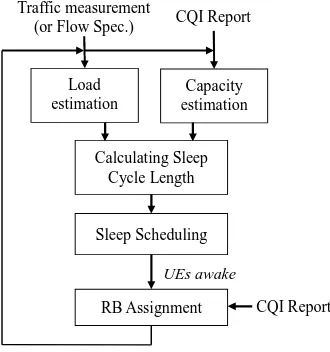
In this paper, the revised version of LBPS-Aggr for LTE is named LTE-LBPS-Aggr. An overview of the proposed scheme is illustrated in Figure 4.
B. LTE-LBPS-Aggr
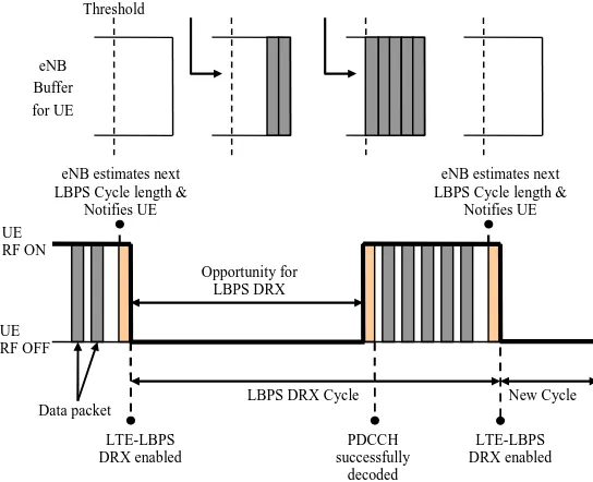
Downlink traffic to all UEs is treated as a single traffic flow in LTE-LBPS-Aggr, but the eNB estimates the traffic load and the channel capacity for each UE respectively. As in our previous work, estimation of the traffic load for a UE is based on traffic measurement and is calculated by exponentially averaging the samples of load measure. On the other hand, estimation of the channel capacity depends on the CQI reports from a UE, meaning that different UEs would have different views of the channel capacity. Estimation of the channel capacity for a UE also requires to address the type of CQI report. Two types of CQI reports are addressed in this paper: UE
RF OFF UE RF ON
eNB Buffer for UE
Data packet
Opportunity for LBPS DRX
LTE-LBPS DRX enabled
LBPS DRX Cycle
PDCCH successfully
decoded Figure 2. Illustration of LTE-LBPS Threshold
eNB estimates next LBPS Cycle length &
Notifies UE
eNB estimates next LBPS Cycle length &
Notifies UE
LTE-LBPS DRX enabled
[image:3.595.349.517.84.254.2]New Cycle
Figure 3. Basic time-frequency resource structure of LTE TTI
One TTI (2 slots) (1ms)
1
2
s
u
b
ca
rr
ie
rs
[image:3.595.322.531.405.596.2]Wideband report and Full-Sub-band report. In Wideband
report, the UE reports one wideband CQI value for the whole system bandwidth. In Full-Sub-band report, in addition to the wideband CQI value, the UE reports a CQI value for each sub-band with system-defined sub-band size. Notations used in estimation of the channel capacity for
UE
i are defined as follows and also illustrated in Figure 5.TTI OFDM
N : The number of OFDM symbols (REs) in a TTI, which is 14 in the case of the normal cyclic prefix length.
Ctrl OFDM
N : The number of OFDM symbols used by the control channels in a TTI.
Resv OFDM
N : The number of OFDM symbols reserved for reference signals in a TTI of 12 subcarriers. Note that the two RBs in a TTI of 12 subcarriers are called a Resource Block Group (RBG) in the paper. Therefore, the number of REs for the user data in an RBG, denoted by TTI
RE
N ,
is calculated as follows.
Resv OFDM Ctrl
OFDM TTI
OFDM TTI
RE N N N
N =( − )×12(subcarriers)−
For the case of Wideband report, the channel capacity estimated for
UE
i in a TTI, denoted byC
iW, are calculated as follows.RBG W i TTI
RE W
i N Eff CQI N
C = × ( )× , where the function of
)
C
(
Wi
QI
Eff
returns the efficiency value for the given wideband CQI value Wi
CQI according to Table 1, and NRBG
is the total number of RBG in the system.
For the case of Full-Sub-band report, the channel capacity estimated for
UE
i in a TTI, denoted by Si
C , are calculated as
follows.
∑
∀ × ×
= k
k S
S RBG S
i TTI
RE S
i N Eff CQI N
C ( ( ) ), where Sk
i CQI is the CQI value for sub-band
k
S , and S RBG
N is the number of RBG
in a sub-band.
As in the estimation of the traffic load for a UE, the estimation of the current channel capacity, denoted byC , is i
calculated by exponentially averaging the samples of each calculation. Since all UEs are treated as a group, the channel capacity for all UEs is calculated by combing the channel capacity estimated for individual UE with the ratio of the UE’s traffic load in the group as follows.
Channel capacity for all UEs (bits/TTI) =
, where λ is the total DL load and i
λ
is the current load ofUE
i. The threshold of data accumulation in LTE-LBPS-Aggr is set as a percentage (α) of the capacity for the user data in a TTI, that is DATA_TH = ×αSystem
C , in which α is set as 80% in the simulation in order to avoid the probability of data overflow in a TTI. Calculation of the length of one sleep-and-awake cycle (in units of TTI) is the same as in our previous work presented in Section II-B. The eNB notifies all UEs of the cycle length via DRX signaling, and all UEs enter DRX mode until the awake TTI for DL reception as illustrated in Figure 2.
IV. PERFORMANCE EVALUATION
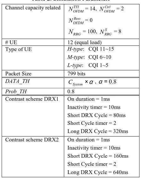
Simulation study is conducted to evaluate the performance of LTE-LBPS-Aggr. Simulation parameters are listed in Table 2. In order to simulate different cases of channel quality, three types of UEs are defined. CQI values for each sub-band in an
H-type (high-quality) UE ranges from 10 to 15 by modulation
of 64QAM. M-type’s (medium quality) CQI ranges from 7 to 9 by modulation of 16QAM. L-type’s (low quality) CQI ranges from 1 to 6 by modulation of QPSK. In the simulation, the average channel capacity of an H-type UE is 56.19Mbps (Wideband report) and 58.38Mbps (Full-Sub-band report).
M-type is 24.41Mbps (Wideband report) and 26.86Mbps
(Full-Sub-band report). L-type is 5.43Mbps (Wideband report) and 6.22Mbps (Full-Sub-band report). The total input load (denoted by λ Μbps) in the simulation depends on the type of UEs in the network, and the utilization factors ρWB and ρSB
[image:4.595.323.529.57.246.2]are defined as the ratio of the total input load over the average channel capacity for the case of Wideband report (WB) and Figure 4. Overview of LTE-LBPS-Aggr
Traffic measurement
(or Flow Spec.) CQI Report
Load estimation
Capacity estimation
Calculating Sleep Cycle Length
Sleep Scheduling
RB Assignment CQI Report
UEs awake
Figure 5. Notations used in capacity estimation 1 TTI, 14 OFDM Symbols
1
2
s
u
b
ca
rr
ie
rs
2 RBs = RBG
………
Control Region=NCtrl OFDM
T
o
ta
l
b
an
d
w
id
th
=
N
R
B
G
CQI report of UEi
(NTTI OFDM =14)
Wideband Sub-band
CQIiW
CQIiS1
Size = NS RBG
CQIiS2
CQIiSk
…
∑
∀
=
i UE
i i System C
C ( )
[image:4.595.92.257.73.249.2]Full-Sub-band report (SB), respectively. Two contrast schemes (DRX1 and DRX2) based on the standard DRX operation are also simulated. Parameters for DRX1 and DRX2 are listed in Table 2. Two performance criteria are investigated and presented in this paper: Power Saving
[image:5.595.56.281.149.435.2]Efficiency (denoted by PSE) and Average Delay (denoted by AvgD), in which PSE is defined as the ratio of radio-off time.
Table 2. Simulation Parameters Channel capacity related TTI
OFDM
N = 14, Ctrl OFDM
N = 2
Resv OFDM
N = 0
RBG
N = 100, S RBG
N = 8
# UE 12 (equal load)
Type of UE H-type: CQI 11~15 M-type: CQI 6~10 L-type: CQI 1~5 Packet Size 799 bits
DATA_TH ×α
System
C , α=0.8
Prob_TH 0.8
Contrast scheme DRX1 On duration = 1ms Inactivity timer = 10ms Short DRX Cycle = 80ms Short Cycle timer = 2 Long DRX Cycle = 320ms Contrast scheme DRX2 On duration = 1ms
Inactivity timer = 10ms Short DRX Cycle = 160ms Short Cycle timer = 2 Long DRX Cycle = 640ms
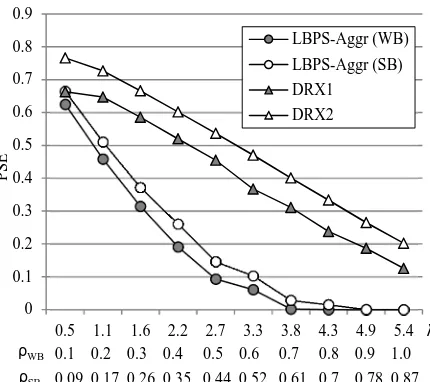
Figure 6 ~ Figure 8 show the result of PSE for each of the following three input cases: all H-type UEs, all M-type UEs, and all L-type UEs. The corresponding result of AvgD for each UE case is displayed in Figure 9 ~ Figure 11, respectively. Note that in the figures there are three rows of index for the x-axis. The upper row is the input load λ in Mbps, the middle row is the utilization factor ρWB for the case of
Wideband report, and the lower row is the utilization factor
ρSB for the case of Full-Sub-band report. Following
observations can be made from the figures.
(1)The scheme of LTE-LBPS-Aggr can adapt to different input load and channel capacity and outperform DRX1 and DRX2 in terms of PSE and AvgD, except in the case of All-L type UEs in Figure 8. Since in the case of All-L
type UEs, the arrival rate of packet with fixed size (799 bits) is pretty low even in high utilization, triggering the inactivity timer of DRX1 and DRX2 to expire and achieve higher PSE in the cost of unacceptable high AvgD in Figure 11.
(2)PSE of Full-Sub-band report is slightly higher than Wideband report in all cases for the proposed LTE-LBPS-Aggr. The reason is the channel capacity by Full-Sub-band report is a little bit higher than the channel capacity by Wideband report, making the utilization factor of ρSB a
little bit smaller than ρWB, which results in longer sleep
cycle length for the case of Full-Sub-band report.
V. CONCLUSION
As a promising technology for 4G mobile communications, LTE has attracted more and more attention in the literature. An important research issue in LTE is power saving at the user side of UE, which is based on the idea of DRX specified in the standard. Based on the authors’ previous work of Load-Based Power Saving (LBPS) in IEEE 802.16, a revised version of LBPS scheme namely LTE-LBPS-Aggr is proposed in the paper. LTE-LBPS-Aggr treats the traffic of all UEs as an aggregate flow and synchronizes the sleep schedule of all UEs. Based on the estimation of the input load by traffic measurement and the estimation of the channel quality by CQI reports, LTE-LBPS-Aggr calculates the proper length of a sleep cycle and notifies all UEs of the time for turning on radio to receive data. Simulation study shows that the power saving efficiency as well as the delay performance of the proposed scheme are better than the standard DRX mechanism. Future work of the research is to incorporate more sophisticate LBPS scheme in LTE to get rid of the constraint of synchronous sleep schedule in LTE-LBPS-Aggr, which can also reduce the overload of PDCCH to notify all UEs of the coming data at the same time.
REFERENCES
[1] U. Varshney, “4G Wireless Networks,” IT Professional, vol. 14, issue 5, Oct. 2012, pp. 34-39.
[2] D. Pareit, B. Lannoo, I. Moerman, and P. Demeester, “The History of WiMAX: A Complete Survey of the Evolution in Certification and Standardization for IEEE 802.16 and WiMAX,” IEEE Communications Surveys & Tutorials, vol. 14, no. 4, pp. 1183–1211, 2012.
[3] 3GPP TS 36.300, “Evolved Universal Terrestrial Radio Access UTRA) and Evolved Universal Terrestrial Radio Access Network (E-UTRAN),” Rel. 8, v8.5.0, May 2008.
[4] 3GPP TS 36.300, “Evolved Universal Terrestrial Radio Access UTRA) and Evolved Universal Terrestrial Radio Access Network (E-UTRAN),” Rel. 10, v10.3.0, Mar. 2011.
[5] 3GPP Contribution, Nokia, R2-071285, "DRX parameters in LTE", March 2007.
[6] C. Bontu, and E. Illidge, “DRX Mechanism for Power Saving in LTE,” IEEE Communications Magazine, vol. 47, no. 6, June 2009, pp. 48-55. [7] C. C. Yang, Y. T. Mai, J. Y. Chen, Y. S. Shen, and Y. C. Kuo, “LBPS: Load-based Power Saving in the IEEE 802.16e Network,” Computers and Electrical Engineering, vol. 38, no. 4, Jul. 2012, pp. 91-905. [8] C. C. Yang, Y. T. Mai, J. Y. Chen, and Y. C. Kuo, “Integrated
Load-Based Power Saving for BS and MSS in the IEEE 802.16e Network,” Wireless Communications and Mobile Computing, 18 Mar. 2013. DOI: 10.1002/wcm.2365
[9] S. Jin, and D. Qiao. “Numerical Analysis of the Power Saving in 3GPP LTE Advanced Wireless Networks,” IEEE Transactions on Vehicular Technology, volume 61, issue 4, May 2012, pp. 1779-1785.
[10] S. Fowler, R. S. Bhamber, and A. Mellouk, “Analysis of Adjustable and Fixed DRX Mechanism for Power Saving in LTE/LTE-Advanced,” Proceedings, IEEE International Conference on Communications (ICC), 2012, pp. 1964-1969.
[11] S. Gao, H. Tian, J. Zhu, and L. Chen, “A More Power-Efficient Adaptive Discontinuous Reception Mechanism in LTE,” Proceedings, IEEE Vehicular Technology Conference (VTC Fall), September 2011, pp. 1-5.
[12] S. Fowler, “Study on Power Saving Based on Radio Frame in LTE Wireless Communication System Using DRX,” Proceedings, IEEE GLOBECOM Workshops, 2011, pp. 1062-1066.
[13] Y.-P. Yu, and K.-T. Feng, “Traffic-Based DRX Cycles Adjustment Scheme for 3GPP LTE Systems,” Proceedings, IEEE Vehicular Technology Conference (VTC Spring), May 2012, pp. 1-5.
0 0.1 0.2 0.3 0.4 0.5 0.6 0.7 0.8 0.9
5.6 11.2 16.9 22.5 28.1 33.7 39.3 45 50.6 56.2 LBPS-Aggr (WB) LBPS-Aggr (SB) DRX1
DRX2
λ ρSB
ρWB 0.1 0.2 0.3 0.4 0.5 0.6 0.7 0.8 0.9 1.0
0.1 0.19 0.29 0.38 0.48 0.58 0.67 0.77 0.87 0.96
P
S
[image:6.595.64.280.54.244.2]E
Figure 6. PSE in the case of All-H UEs
0 5 10 15 20 25
5.6 11.2 16.9 22.5 28.1 33.7 39.3 45 50.6 56.2 LBPS-Aggr (WB) LBPS-Aggr (SB) DRX1
DRX2
λ ρSB
ρWB 0.1 0.2 0.3 0.4 0.5 0.6 0.7 0.8 0.9 1.0
0.1 0.19 0.29 0.38 0.48 0.58 0.67 0.77 0.87 0.96
A
v
g
D
(
m
s)
Figure 9. AvgD in the case of All-H UEs
0 0.1 0.2 0.3 0.4 0.5 0.6 0.7 0.8 0.9
2.4 4.9 7.3 9.8 12.2 14.6 17.1 19.5 22 24.4 LBPS-Aggr (WB) LBPS-Aggr (SB) DRX1
DRX2
λ ρSB
ρWB 0.1 0.2 0.3 0.4 0.5 0.6 0.7 0.8 0.9 1.0
0.09 0.18 0.27 0.36 0.45 0.55 0.64 0.73 0.82 0.91
P
S
[image:6.595.316.534.55.251.2]E
Figure 7. PSE in the case of All-M UEs
0 10 20 30 40 50 60 70
2.4 4.9 7.3 9.8 12.2 14.6 17.1 19.5 22 24.4 LBPS-Aggr (WB) LBPS-Aggr (SB) DRX1
DRX2
λ ρSB
ρWB 0.1 0.2 0.3 0.4 0.5 0.6 0.7 0.8 0.9 1.0
0.09 0.18 0.27 0.36 0.45 0.55 0.64 0.73 0.82 0.91
A
v
g
D
(
m
s)
Figure 10. AvgD in the case of All-M UEs
0 0.1 0.2 0.3 0.4 0.5 0.6 0.7 0.8 0.9
0.5 1.1 1.6 2.2 2.7 3.3 3.8 4.3 4.9 5.4 LBPS-Aggr (WB) LBPS-Aggr (SB) DRX1
DRX2
λ ρSB
ρWB 0.1 0.2 0.3 0.4 0.5 0.6 0.7 0.8 0.9 1.0
0.09 0.17 0.26 0.35 0.44 0.52 0.61 0.7 0.78 0.87
P
S
E
0 20 40 60 80 100 120 140 160
0.5 1.1 1.6 2.2 2.7 3.3 3.8 4.3 4.9 5.4 LBPS-Aggr (WB)
LBPS-Aggr (SB) DRX1
DRX2
λ ρSB
ρWB 0.1 0.2 0.3 0.4 0.5 0.6 0.7 0.8 0.9 1.0
0.09 0.17 0.26 0.35 0.44 0.52 0.61 0.7 0.78 0.87
A
v
g
D
(
m
[image:6.595.311.534.57.506.2]s)
[image:6.595.64.281.276.465.2] [image:6.595.65.280.501.692.2]