Implementation of Temperature Process Control
using Soft Computing Techniques
P.Poongodi1, R.Madhusudhanan2 and N.Prema3
Abstract — Objective of this paper is to design various controllers for a temperature process control. PID controller is the well known and most widely used in the industries. Internal Model Control (IMC) has become the leading form of advanced control in the process industry. Modified form of IMC-PID and Fuzzy PID Controllers are designed for First Order Plus Dead Time (FOPTD) process model. The comparative performance analysis has been done for PID, IMC, IMC-PID, and Fuzzy-PID controllers. The proposed Fuzzy-PID controller shows better performance than the other.
Index Terms—PID, IMC, IMC-PID, Fuzzy-PID
I. INTRODUCTION
Proportional Integral Derivative controller is one of the earlier control algorithm and strategies. The PID controller was first introduced in 1940 and has most widely used in the industries. The PID controller used for industries application are used to control the variables like fluid flow, pressure, level, temperature, consistency, density. The controller maintains the process output level so that difference between the process variable and the set point is minimal. The real time temperature control system design for PID controller using Zeigler Nichols method, Cohen Coon method and Wange method are detailed [2].The intelligent fuzzy PID controller for temperature is implemented [7] for different operating range. The temperature process is highly nonlinear and design of robust controllers for such nonlinear systems is a challenge. This paper proposes a novel intelligent method for the control of temperature process. The traditional PI controllers which are in practice produce high overshoot and the design procedure seems complex. The proposed intelligent controller offers better performance in terms of overshoot and settling time and thus increases the robustness of the system. Section II provides the description of temperature process system and its modeling. Section III provides the control strategies applied. Section IV provides the results and discussion.
Manuscript received January 25, 2016; revised March 09, 2016 P. Poongodi is associated as Senior Professor in Department of Electronics and Communication Engineering, Karpagam College of
Engineering, Coimbatore-641 032, Tamilnadu, India. (e-mail:
R.Madhusudhanan is associated as Research Scholar in Department of Electronics and Communication Engineering, Karpagam College of Engineering, Coimbatore-641 032, Tamilnadu, India. (phone: +91 0422
2619047; Mobile: +91 09486185533; fax: +91 0422 261046; e-mail: [email protected]).
N.Prema is associated as Post Graduate scholar in Department of Electronics and Communication Engineering, Karpagam College of
Engineering, Coimbatore-641 032, Tamilnadu, India. (e-mail:
II. SYSTEM DESCRIPTION
A. Temperature Process System
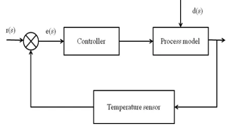
[image:1.595.314.538.367.491.2]Temperature process system typically contains a controller unit, temperature input unit and controller output unit. The temperature sensor forms the measuring unit. The Solid State Relay drive is driven by the controller output unit. The aim of the project is to control the temperature with in a desired limit. The temperature controller can be used to control the temperature of the any system. The temperature process is a non linear system. The process system contains a first order transfer function with a time constant [6] .The block diagram for temperature process is shown in Fig. 1.
Fig. 1. Block diagram of temperature process control
B. System Modeling
The most commonly industrial process can be modeled
by first order plus dead time models. The system modeling can be done in two ways one is the mathematical modeling and another one is the empirical modeling. Temperature process was modeled using the empirical modeling. The process model of the transfer function is obtained from the step response. The FOPDT parameters that are to be determined are the process gain (K), delay time (td), time constant (
) units of minutes or seconds [4]. The First order plus time delay process equation is given by,Where, =Process gain, = Delay time, = Time constant. The temperature process of the transfer function is experimentally obtained as,
III. CONTROLLER STRATEGIES
Fuzzy PID control. The control using Genetic algorithm is detailed in [5] for temperature process.
A. PID Controller
The PID Controller has Proportional, Integral and Derivative actions inbuilt [12].
Proportional Action
The output is proportional to the error at the instant time„t‟. It is reducing the rise time of process.
Integral Action
The output is proportional to the integral error at the instant time„t‟; it can be interpreted at the accumulation of the past error. The controller removes the steady state error but maintain the transient response.
Derivative Action
The output is proportional to the derivative error at the instant time „t‟; it can be interpreted at the prediction of the future error. The controller affects the system by increasing stability and by reducing overshoot, improving the transient response.
The transfer function of the PID controller,
(1) = Proportional gain, = Integral gain, =Derivative gain
The parameters, , , and values are obtained using Cohen and Coon tuning method as 0.17, 0.085 and 0.0213 respectively.
B. IMC Controller
The internal model control (IMC) algorithm is widely
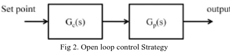
used in dead time process industries. IMC controller implementations are becoming more popular than the standard industrial controllers remain the proportional plus integral and derivative (PID) controllers. In the Fig. 2 if the controller transfer function Gc(s) is the inverse of process transfer function Gp(s), set point tracking could be achieved.ie., if . Where is
[image:2.595.315.540.77.180.2]process model.
Fig 2. Open loop control Strategy
Internal model control philosophy relies on the principle of the internal model principle which states that the control, can be achieved only if the control system encapsulates the representation of process to be controlled. The system often affected by unknown disturbance. The controller has been developed based on the perfect model, so it can be named as internal model controller as detailed in [8]. The model mismatch is common in real time
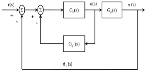
[image:2.595.60.289.622.674.2]implementation. The general block diagram is shown in Fig. 3.
Fig. 3. Block diagram of IMC controller
where, is disturbance, is estimated disturbance, Q(s) is Internal Model Controller, is set point, is error to modify the set point, is the manipulated input which is introduced to both the real process and its model. is the measured process output. is the unknown disturbance at process output. is process model output. is the calculated new disturbance
(2) (3) Assume d(s) is zero and if Gp1(s) = Gp(s)
(4) Since (5) Substituting d1(s) and rearranging the above equation
(6) The closed loop transfer function of IMC Structure after substitution and rearranging
(7) From this closed loop expression, we can see that if and if , then perfect set point tracking and disturbance rejection is achieved. Notice that, theoretically even if
To improve robustness, the effects of process model mismatch should be minimized. Since discrepancies between process and model behavior usually occur at high frequency end of systems frequency response, a low pass filter is usually added to attenuate the effect of process model mismatch. Thus internal model controller is usually designed as the inverse of process model in series with a low pass filter.
(10) An internal model controller Q(s) is found by dividing process model, Gp1(s) is divided into two parts,
(11) Where and is invertible and non-invertible components. The non-invertible component contain term which if inverted, will lead to instability and reliability problems ie., terms containing positive zeros and time delays.
Next set and
C. IMC-PID Controller
[image:3.595.299.547.165.489.2]The IMC philosophy can also be used to generate settings for conventional PI or PID Controllers. It provides time delay compensation. The filter can be used to shape both set point tracking and disturbance rejection. For stable processes with a time delay the IMC-based PID procedure will not give exactly the same performance as IMC, because a Pade‟s approximation for dead time is used in the controller design. IMC based PID controller [10] is achieved by the rearrangement IMC controller block diagram to form a standard feedback control loop as shown in Fig 4.
Fig. 4 Modification block diagram of IMC
The above block diagram is reduced IMC PID Controller as shown in Fig 5.
Fig. 5. Block diagram of IMC-PID controller
(12)
The common process transfer function is equal to PID-type feedback controller in IMC law. It is an advanced controller. The filter structure for IMC PID is given in [1].
(13) The time delay can be approximated using exponential series of order up to one.
ie., (14) Therefore
(15) With
and
(16)
Rearranging the above
(17) Comparing this with ideal PID controller,
(18) we find the corresponding proportional gain and integral time as
and
We can also replace the time delay with its pade approximation,
(19)
(20) With
[image:3.595.54.289.387.508.2](22) Substituting the above in Gpid(s) and rearranging we get
(23) Comparing the above with ideal PID controller, The corresponding proportional gain and integral time and derivative time as
(24)
(25)
(26)
D. Fuzzy-PID Controller
[image:4.595.309.547.121.278.2]The design of fuzzy controller generally comprises of three steps: Fuzzification, applying the fuzzy rules, and defuzzification. Fuzzification aims to convert a single (crisp) input value into corresponding fuzzy-set values. Applying the fuzzy rules entails processing the “fuzzy” information. The third step, defuzzification, converts the internal fuzzy results back to a crisp output value. In Fuzzy PID controller the three parameters of PID controller (i.e.) KP, KI, KD are tuned using Fuzzy logic. The conventional PID controller coefficients are not proper for the nonlinear with unpredictable parameters variation. The design of fuzzy PID controller is detailed [13]. The design of PD and PID controllers using fuzzy in industrial application is given in [9]. The membership functions associated to the control variables have been chosen with triangular shapes. Universe of discourse is divided into five overlapping fuzzy sets: NB (Negative Big), NM (Negative Medium), ZE (Zero), PM (Positive Medium), and PB (Positive Big) [11]. The block diagram for Fuzzy Logic Controller (FLC) is shown in Fig. 6.
Fig. 6. Block diagram of fuzzy logic controller
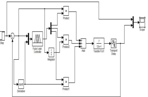
In the fuzzy membership function editor, the number of membership function and type of membership function is chosen as triangular. The Fig.7 shows the Fuzzy PID controller implementation
Fig. 7. Fuzzy PID Controller using MATLAB/ simulink The implementation of Fuzzy PID Controller is done by using a FLC simulink block. The FLC block has a parameter to be Fuzzy Inference System (FIS) file or a structure. In the FIS editor the input to the controller ie., error and change in error is defined. The output of the controller ie, the Kp, Ki, Kd gains are defined. The error and change in error range are chosen between (-5 5) and (-1 1) respectively. The input crisp values are converted to fuzzy values by fuzzification process. The linguistic variables for the inputs are defined as Negative Big(NB), Negative Medium (NM), Zero(Z), Positive Medium(PM), Positive Big (PB). Similarly, for output the Kp, Ki and Kd range are (-1 100), (3 15) and (0.1 0.9). The gains and the inputs are converted to fuzzy values by the triangular membership function with values between (0 1). The linguistic variables for the outputs are also defined as NB, NM, Z, PM, PB. Based on the linguistic variables the input and output rules are formed. Around 25 rules are formed. The simulation is carried using MATLAB with Fuzzy Logic Tool Box [3].
IV. RESULTANDDISCUSSION
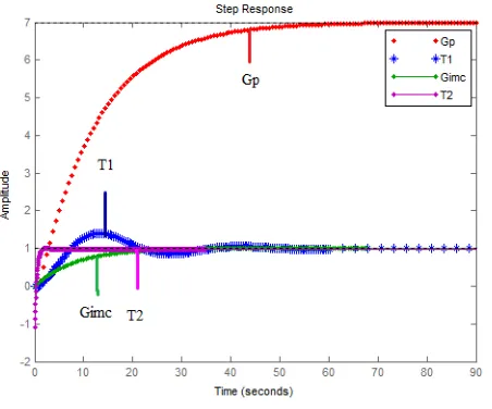
[image:4.595.49.286.584.752.2]Fig. 8. Comparative response of various controllers
[image:5.595.45.291.343.493.2]A reference unit step input at time =0 is given as the input to the Fuzzy PID controller has the least settling time and rise time of 0.1sec and 0.05 sec. The step response of Fuzzy PID is shown in Fig. 9.
Fig. 9. Step response of Fuzzy- PID controller
The Table 1 shows the summarized performance indices of conventional PID, IMC, IMC-PID, and Fuzzy PID Controllers
TABLEI
Performance indices of various controllers
Controller Type Settling
Time Sec
Rise Time Sec
Over shoot % Conventional
PID 47.8 5.01 1.5
IMC 30 17.6 1
IMC-PID 1.47 0.9 0
Fuzzy-PID 0.1 0.05 0
The proposed fuzzy PID controller response has the least settling time and rise time of 0.1sec and 0.05 sec respectively with no overshoot.
ACKNOWLEDGMENT
The authors are thankful to the management of the
institution for providing good infrastructure to carry out this work. The authors are also gratitude to the projectcoordinator Dr.C.Aravind for lending his support to carry out this work. The authors are also thankful to the members of the department for providing excellent learning platform and ample motivation for the progress of this research work.
REFERENCES
[1] Ian G.Horn, Jeffery R.Arulandu, Christopher J. Gombas, Jeremy
G.VanAntwerp, and Richard D.Braatz, “Improved filter design in internal model control”, Imd.Eng.Chem, vol.35, pp. 3437-3441,1996.
[2] A. R Laware, V. S. Bandal, and D.B. Talange, “Real time
temperature control system using PID controller and supervisory control and data acquisition system (SCADA)”. International Journal of Application or Innovation in Engineering & Management, vol. 2, no. 2, 88-95,2013.
[3] Math Works Inc., “Fuzzy logic tool box for use with MATLAB -
Users Guide Version 2”,1999.
[4] N.Nithyarani and S. M. GirirajKumar, “Model identification of
temperature proces and tuning with advanced control techniques”,
IJIREEICE, vol. 1, no.9, pp. 443-447, 2013.
[5] N.Nithyarani,S. M.GirirajKumar and N.Anantharaman, “Modeling
and control of temperature process using genetic algorithm”, IJAREEIE, vol. 2, no.11, pp. 5355-5364, 2013.
[6] N.Nithyarani and S.Ranganathan, “Advances in control techniques
and process analysis with LabVIEW and DCS”, International Journal of Electronics, Communication and Instrumentation Engineering Research and Development, vol. 3, no. 2, pp. 137-148, 2013.
[7] D.Pamela and T.Jebarajan, “Intelligent controller for temperature
process”, International Journal of Control and Automation,vol. 6, no. 5, pp. 191-198, 2013.
[8] S.B.Radhika and A.Nasar, “Internal model control based preheating
zone temperature control for varying time delay uncertainty of the reheating furnace”, International Journal of science and Research, vol. 4, no. 7, pp. 78-82, 2015.
[9] Ritu Shakya, Kritika Rajanwal, Sanskriti Patel and Smita Dinkar.
“Design and simulation of PD, PID and fuzzy logic controller for industrial application”, International Journal of Information and Computation Technology, vol. 4, no. 4, pp. 363-368, 2015
[10] M.Shamsuzzoha, “IMC-PID controller design for improved
disturbance rejection of time-delayed process”, vol. 46, pp. 2077-2091, 2007
[11] Umesh Kumar Bansal and Rakesh Narvey, “Speed control of DC
motor using fuzzy PID controller”, Advance in Electronic and Electric Engineering, vol. 3, no. 9, pp. 1209-1220, 2013.
[12] T.VanDerPuy, “A study on PID temperature control” , For ENGR
315, Control Systems.
[13] Zulfatman and M.F.Rahmat, “Application of self-tuning fuzzy PID