http://dx.doi.org/10.4236/ijcns.2012.510070 Published Online October 2012 (http://www.SciRP.org/journal/ijcns)
Distributed Relay Beamforming in Cognitive Two-Way
Networks: SINR Balancing Approach
Seyed Hamid Safavi, Mehrdad Ardebilipour
Faculty of Electrical and Computer Engineering, K.N.Toosi University of Technology, Tehran, Iran Email: s.hamid_safavi@ee.kntu.ac.ir, mehrdad@eetd.kntu.ac.ir
Received August 16, 2012; revised September 14, 2012; accepted September 24,2012
ABSTRACT
In this paper, we study the problem of distributed relay beamforming for a bidirectional cognitive relay network which consists of two secondary transceivers and K ognitive relay nodes and a primary network with a transmitter and receiver, using underlay model. For effective use of spectrum, we propose a Multiple Access Broadcasting (MABC) two-way relaying scheme for cognitive networks. The two transceivers transmit their data towards the relays and then relays re-transmit the processed form of signal towards the receiver. Our aim is to design the beamforming coefficients to maxi-mize quality of service (QoS) for the secondary network while satisfying tolerable interference constraint for the pri-mary network. We show that this approach yields a closed-form solution. Our simulation results show that the maxi-mum achievable SINR improved while the tolerable interference temperature becomes not strict for primary receiver.
Keywords: Cognitive Radio; Two-Way Relay Networks; Beamforming
1. Introduction
With the explosive proliferation of wireless systems, the demand for radio spectrum has been increasing rapidly. As a result, the radio spectrum has become a scarce re-source. Cognitive radio (CR) has recently emerged as a promising technology to address the need for intelligent spectrum allocation [1]. In cognitive radio networks, un- licensed (secondary) users can access the licensed (pri-mary) spectrum either on non-interference or interference tolerant basis. There are three main cognitive radio net-work paradigms: underlay, overlay, and interweave [2]. In the interweave approach, cognitive transmitters are required to sense the spectrum and transmit signals only when frequency holes are available. Spectrum holes are the most obvious opportunities to be exploited by CR, but higher spectrum utilization is anticipated in overlay and underlay approaches where coexistence between the primary user (PU) and secondary users (SUs) is permit-ted. We have adopted the underlay paradigm due to its advantages from an implementation viewpoint [3] in this work. In the underlay approach, the SUs are allowed to utilize the spectrum of the PU only if the interference generated by the SUs at the primary receivers is below some acceptable threshold which is commonly known as interference temperature [2,4]. This constraint limits the allowed transmit power of SUs and consequently the QoS of the secondary network. To address this issue, cooperation between SUs is a potential way to improve
the secondary network QoS while performance of the primary network is not affected. A variety of cooperative strategies have been proposed with different design crite-ria and assumptions. Among them, distributed beaform- ing is an efficient technique to enable concurrent trans-mission of SUs and PUs. Also, in the overlay approach, the SU shares part of its power resources with the PU to provide a relay-assisted transmission.
Recently, motivated by cognitive radio and coopera-tive communications, cognicoopera-tive relay networks have gai- ned considerable research interest. As we explained be-fore, distributed relay beamforming, in which the objec-tive is to determine the beamforming weights according to some optimality criterion, have received a lot of atten-tion in non-cognitive relay networks [5-8]. However, the literature on cooperative relaying techniques such as dis-tributed relay beamforming with explicit incorporation of cognitive radio concepts is very sparse. Especially, the use of beamforming in cognitive relay networks is much more challenging because of the existence of the bidirec-tional interferences between the primary and secondary networks. In addition, two-way relaying technique along with beamforming can further improve the spectrum ef-ficiency in cognitive relay networks [9,10]. Two-way re- laying scheme can be categorized in three main groups;
and well investigated in [11]. A beamforming technique has been proposed in [9] to maximize achievable sum rate in a multi-antenna cognitive two-way relaying net-work without considering the mutual interference. To the best of our knowledge, the problem of optimal distrib-uted beamforming for an underlay cognitive two-way re- lay network has not been well addressed.
In this work, we propose a beamforming approach to maximize QoS requirements for the secondary network while satisfying interference temperature constraint for the primary network in an underlay cognitive two-way relay network. Our goal is to obtain beamforming coeffi-cients of the secondary relays as the design parameters, such that the secondary network QoS measured by the signal-to-interference-plus-noise ratio (SINR) at the sec-ondary destination is maximized while interference from secondary network to primary network is constrainted to a predefined value.
Throughout this paper, we use the following standard notations:
T and
H
ag
diag arepresent the transpose and the hermitian transpose, respectively. The notation
is a vector which contains the diagonal entries of the square matrix A and is a diagonal ma-trix whose diagonal elements are different entries of the vector a. max and
A
di
A max
A represent principaleigenvalue and eigenvector of matrix A, respectively. denotes the statistical expectation and I is the identity matrix.
E
The reminder of paper is organized as follows. In the next section system model and problem formulation for cognitive two-way relaying scheme are described. In Section 3, the SINR balancing under interference con-straint is developed. Simulation results are given in Sec-tion 4 and finally, the main results are summarized in Section 5.
2. System Model
[image:2.595.81.266.577.717.2]As shown in Figure 1, we consider a set of SUs coexist and operate in the licenced primary band. The secondary
Figure 1. A Two-way cognitive relay network.
network consists of a pair of source node exchange in-formation with the assistance of K randomly located re-lay nodes via MABC two-way rere-laying scheme. As we consider the underlay paradigm in the model, the secon-dary network utilizes the primary network’s spectrum to transmit its data under a simple two-phase amplify-and- phase-adjust-and-forward protocol simultaneously with the primary transmission. It is reasonable for secondary network that have the full channel state information (CSI) by a band manager that interpose between the primary and secondary networks [12].
We denote the channel vector between the n’th
n1, 2
= T
transceiver and the relays by
1 2 n f fn n fkn
f
=f f f T
f
= g g g T
and channel coefficients between the primary transmitter and receiver by hp. We also consider mutual interference between the primary and secondary networks in this work. Hence p 1p 2p kp de-
note the interference channel vector from PU transmitter to the relays, while p 1p 2p kp is the channel
vector between relays and PU receiver. We assume that the forward channels from each transceiver to the relay nodes are reciprocal to the backward channels from the relay nodes to each corresponding transceiver [13]. Also, a flat fading condition is considered so that the channel realizations vary independently from one frame to an-other while they remain fixed within each frame. Any interference from the secondary transceivers at the pri-mary receiver in the first time slot as well as interference from the primary transmitter at the secondary transceiv-ers in the second time slot is considered as additive white Gaussian noise (AWGN) [4].
g
During the first time slot (multiple access phase), both transceivers simultaneously transmit their data to the relays. The received signals in relays from transceivers as well as interference from PU transmitter can be repre-sented, in vector form, as
1 1 1 1 2 2 2 p p p
P s P s P s
x f f f υ
1
(1.1)
where x is the K complex vector of the received signals at the relays, P1, P2 and Pp are the transmit pow-ers of Transceivpow-ers 1, 2 and PU transmitter, respectively. Let S1, S2 represent the information symbols transmitted by transceivers 1, 2 and p1
2 p
s , s represent the infor-mation symbols transmitted by PU transmitter in the first and second time slot respectively. v is the K1 com-plex vector of the relay noises with covariance matrix
2
I
* w
.
In the second time slot (broadcasting phase), the i’th relay multiplies its received signal by a complex weight
i and transmits the so-obtained signal can be
ex-pressed as
t Wx * * * 1, 2, , k
w w w
(1.2)
transceivers can be written as:
1
1p psp n
f υ
1 1 1
1 1 1 1 2 2 2
T T
y n
P s P s P
f Wx
f W f f (1.3)
1
2 p psp n f υ 2 2 2
2 1 1 1 2 2 2 T
T
y n
P s P s P
f Wx
f W f f (1.4)
Using aTdiag
b =bTdiag
a , we rewrite (3) and (4) as 1 1 1 1 1
1 H
p p
y P s
P s
w F f w F f
2 1 2 2
1 1 1
H H H p P s n
w F f
w Fυ (1.5)
2 1 2 1 1
1 H
p p
y P s
P s
w F f w F f
2 2 2 2
2 2 2
H H H p P s n
w F f
w Fυ
H
(1.6)
where w diag W , F1 diag f1 , F2 diag
f2 . The noise process is assumed to be zero-mean and spa-tially white with variance σ2. We will later explain how each relay can compute its own optimal beamforming weight. Since the knowledge of f1 and s1 are available at Transceiver 1, thus transceiver 1 can subtracts the first term in (5) and manipulate the remaining term to have
1 1 1 1 1 1
1
2 1 2 2 1
desiredsignal interference
H
H H
p p
y y P s
P s P
w F f
w F f w F f
1 1
noise
H p
s w Fυn (1.7)
and similarly
2 2 2 2 2 2
1
1 2 1 1 2
desired signal interference
H
H H
p p
y y P s
P s P
w F f
w F f w F f
2 2
noise
H p
s w Fυn (1.8)
The received signal at the primary receiver can be ex-pressed as
2 21 1 1 2 2 2 2
noise desired signal
1 1 1 2 interferencefrom secondary ne
1
self interference T
p p p p p p
T p p p p
p p p p p p
H H 1 2 2 twork p p H
p p p
s n
s
f υ
f w G υ
H
p p p p
y P h s n
P h s
P s P s P
P h s n
P s P
P s g Wx g W f f
w G f w G
w G f
(1.9)
3. SINR Balancing
In this section, our goal is to find the beamforming
weight vector W in order to SINR balancing at the sec-ondary network subject to an interference power con-straint at the primary network. Mathematically, the opti-mization problem can be represented as follows
1 2
max min ,
I th
SINR SINR
Subject to P I
w (1.10)
where SINRm is defined as the ratio of the desired signal power to the interference plus noise power at the m’th transceiver for m = 1, 2 and PI denotes the interference power. These parameters can be calculated as follows
1, 2 m m m s m i n P SINR m P P
(1.11)
1
* 2 1 2 2 2 2 1
2
2 1 2 2 1 2
1
2
2
H H H
s
H H H
H H
H
P E P s s
P E E s
P P
w F f f F w w F f f F w
w hh w w Aw
1 2= 2 1 h F f F f
(1.12)
H
A hh
.
where ,
* 1
1 1
2 1 1
2 1 1 1
1 2
H H H
i p p p p
H H H
p p p p
H H
P E P s s
P E E s
P
w F f f F w
w F f f F w
w kk w
1
(1.13)
where K F f p.
12
1 1 1
2
1 1
2 2
1 H H H n
H H H
H
P E E n
E
w Fυυ F w w F υυ F w
w D w
1 1 1
(1.14)
H D F F
2 2 2 1 2 2 2 H s H H i p H n P P P P P , similarly where w Aw w LL w
w D w
2
where L F f p 2 2 2
H
D F F
, .
2 1 2 2
1 2 2 2 1 2 2 H
H H H
p H H H p H H P SINR P P P P w Aw
w D w w kk w
w Aw
w D kk w
w Aw w Bw
(1.15)
1 1 2 2
2 1 2 2 2 1 2 H H H H H P SINR P P w A w D w
w A
w D
w Aw w Cw
H H H
p H p P P w
w LL w w LL w 2 1 2 2
(1.16) where H p H p P P
B D kk
C D LL
Using (9) so the interference component power which consists of secondary network interference and self in-terference can be written as
* * 1 1 1 1 1* 2 2 2 2 2
1 1 2 2 2 1 1 2 1 1
H H H
I p p
H H H
p p
H H H
p p
H H
p p p p p
H H H
H H H
p p
H
P E P s s
E P s s
E
E P s s
P E s P
P E s
w G f f G w w G f f G w w G υυ G w
w G f f G w
w UU w w Y
w ZZ w w G
w Qw
2 2 2 2 1 1 H H H H p p E s E Y wυυ G w
1 2 p p (1.17) where p p
U G f Y G f Z G f
2 and
1 2
H H H H
p Z G Gp p
1 2
NR SINR
P P P
Q UU YY Z
(1.18)
Note that at the optimum, it is required that
SI
(1.19) Otherwise, if, for example, SINR1 > SINR2, then P2 can be reduced such that SINR1 = SINR2 and this reduc-tion of P2 will not violate the power constraint. Using (15) and (19) the optimization problem (10) can be written as
2 2 H H H th P I w Aw w Bw w Qw max . . S t
(1.20)
to solve (20), let us write the weight vector w as
1 2 1 th H I
w Q w
w w
(1.21)
then we can rewrite the optimization problem as
2 2
2 max
. . 1,
H H
th
P I I
S t I I
w Aw w Bw w
(1.22)
It is easy to show that the inequality constraint in (22) will be satisfied with equality at the optimum. As the objective function in (22) is monotonically increasing in
I, for any value of w, this objective function is maxi-mized for I - Ith.
2 2
2 max
. . 1
H th H th P I I S t w Aw w Bw w
12
th
I B I A
(1.23)
It is obvious that the optimization problem (23) is in the form of Rayleigh-Ritz ratio, in which objective func-tion is globally maximized when WH chosen as the con-stant factor of the principal eigenvector of the matrix
.
1
2 max Ith
w B I A
(1.24) as a result, the beamforming weight vector can be written as
1 2 max 11 2 1 2 2 1 2 1 2 th th I I w Q
Q BQ I Q AQ
(1.25)
and the maximum achievable SINR can be expressed as
max 2
1
1 2 1 2 2 1 2 1 2 max
th th
SINR P I
I
Q BQ I Q AQ (1.26)
As the level of interference temperature can be esti-mated at the secondary network [2] and we assume that the secondary network have full CSI, optimal beam-forming coefficient in each relay can be calculated from (25).
4. Simulation Results
[image:4.595.54.294.270.574.2]In our simulation results we consider a secondary net-work with K = 20, 30, 40 relay nodes, and the channel coefficients are generated independently as complex Gaussian random variables with unit variance in each simulation run. All noise powers including relay noises, secondary and primary receiver noises is assumed to be 0 dBW. Throughout our numerical examples, the transmit power of transceivers and PU is also considered to be equal to 0 dBW. The average value of each quantity is obtained by averaging the corresponding quantity over 104 simulation runs.
maxi-mum achievable SINRs versus the maximaxi-mum interfer-ence power that primary receiver can tolerate for three different values of K. As can be seen from this figure, as we increase K, the maximum achievable SINRs increase. The achieved improvement from 30 relays to 40 has be-come lower than the improvement of 20 to 30.
[image:5.595.62.283.313.476.2]Figure 3 shows the average values of the relay trans-mit power for three different values of K. It is reasonable that, as we increase the number of relays, total power dissipated in the relays doesn’t change considerably for fixed tolerable interference. However because of the beamforming effect and phase compensation, SINR of each transceiver’s is improved.
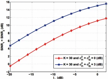
Figure 4 illustrates the average values of the maxi-mum achievable SINRs versus the maximaxi-mum interfer-ence power that primary receiver can tolerate for 30 re-lays and two different scenarios: 1)
1 2 f f
and 2) . As can be seen from this figure,
2 2
= = 0 dB
2 2 1 = 2 = 3 d f f
[image:5.595.62.285.526.696.2] B
Figure 2. The average values of the maximum achievable SINRs versus the interference temperature for three dif- ferent values of K.
Figure 3. Total relay Power dissipated in the network ver- sus the interference temperature for three different values of K.
Figure 4. The average values of the maximum achievable SINRs versus the interference temperature for two different
scenarios; 1) 2 2 ; 2) .
1= 2= 0 dB
f f
σ σ 2 2
1= 2= 3 dB
f f
σ σ
by increasing the interference temperature and improving the quality of secondary channels, SINR improvement decreases. Because the interference constraint become strict.
5. Conclusion
In this paper, we developed the distributed relay beam- forming for an underlay bidirectional cognitive network which consists of two transceivers and K relay nodes between them all equipped with single-antenna in the presence of primary network. For effective use of spec- trum, MABC two-way relaying which needs two time slots to swap two symbols between the two transceivers proposed for cognitive networks. We study SINR balanc- ing technique where the smaller of the two transceiver SINRs is maximized while keeping the interference power below interference temperature. We herein have shown that this approach leads to a closed-form solution.
REFERENCES
[1] S. Haykin, “Cognitive Radio: Brain-Empowered Wireless Communications,” IEEE Journal on Selected Areas in Communications, Vol. 23, No. 2, 2005, pp. 201-220. doi:10.1109/JSAC.2004.839380
[2] A. Goldsmith, S. A. Jafar, I. Maric and S. Srinivasa, “Brea- king Spectrum Gridlock with Cognitive Radios: An In- formation Theoretic Perspective,” Proceedings of the IEEE, Vol. 97, No. 5, 2009, pp. 894-914.
doi:10.1109/JPROC.2009.2015717
[3] R. Zhang, “On Peak versus Average Interference Power Constraints for Protecting Primary Users in Cognitive Radio Networks,” IEEE Transactions on Wireless Com- munications, Vol. 8, No. 4, 2009, pp. 2112-2120.
doi:10.1109/TWC.2009.080714
tive Radio Relay Channels,” IEEE Transactions on Wire- less Communications, Vol. 9, No. 5, 2010, pp. 1698-1707. doi:10.1109/TCOMM.2010.05.090600
[5] V. Havary-Nassab, S. Shahbazpanahi, A. Grami and Z.-Q. Luo, “Distributed Beamforming for Relay Networks Ba- sed on Second-Order Statistics of the Channel State In- formation,” IEEE Transactions on Signal Processing, Vol. 56, No. 9, 2008, pp. 4306-4316.
doi:10.1109/TSP.2008.925945
[6] S. Fazeli-Dehkordy, S. Shahbazpanahi and S. Gazor, “Multiple Peer-to-Peer Communications Using a Network of Relays,” IEEE Transactions on Signal Processing, Vol. 57, No. 8, 2009, pp. 3053-3062.
[7] J. Li, A. P. Petropulu and H. V. Poor, “Cooperative Tran- smission for Relay Networks Based on Second-Order Statistics of Channel State Information,” IEEE Transac- tions on Signal Processing, Vol. 59, No. 3, 2011, pp. 1280-1291. doi:10.1109/TSP.2010.2094614
[8] A. S. Behbahani and A. M. Eltawil, “Amplify and For-ward Relay Networks under Intereference Power Con- straint,” IEEE Transactions on Wireless Communications, Vol. 8, No. 11, 2009, pp. 5422-5426.
doi:10.1109/TWC.2009.081522
[9] K. Jitvanichphaibool, Y.-C. Liang and R. Zhang, “Beam-forming and Power Control for Multi-Antenna Cognitive Two-Way Relaying,” IEEE Wireless Communications and Networking Conference, Singapore, 5-8 April 2009, pp. 1-6. doi:10.1109/WCNC.2009.4917611
[10] A. Alizadeh, S. M. S. Sadough and N. Khajavi, “Optimal Beamforming in Cognitive Two-Way Relay Networks,” IEEE 21st International Symposium on Personal Indoor and Mobile Radio Communications (PIMRC), Instanbul, 26-29 September 2010, p. 2331.
[11] V. Havary-Nassab, S. Shahbazpanahi and A. Grami, “Op- timal Distributed Beamforming for Two-Way Relay Net-works,” IEEE Transactions on Signal Processing, Vol. 58, No. 3, 2010, pp. 1238-1250.
doi:10.1109/TSP.2009.2026067
[12] J. M. Peha, “Approaches to Spectrum Sharing,” IEEE Communications Magazine, Vol. 43, No. 2, 2005, pp. 10- 12. doi:10.1109/MCOM.2005.1391490