DOI: 10.4236/msce.2018.62001 Feb. 12, 2018 1 Journal of Materials Science and Chemical Engineering
Dan Wang
1, Changyuan Lu
1, Xingli Zou
1, Kai Zheng
1, Zhongfu Zhou
1,2, Xionggang Lu
1*1State Key Laboratory of Advanced Special Steel & Shanghai Key Laboratory of Advanced Ferrometallurgy, School of Materials
Science and Engineering, Shanghai University, Shanghai, China
2Department of Physics, Aberystwyth University, Aberystwyth, UK
Abstract
The electrolytic production of nickel-copper alloy by electrochemical reduc-tion of converter matte in molten salt has been investigated. The sintered solid porous pellets of Ni3S2, Cu2S and converter matte were electrolyzed at a
vol-tage of 3.0 V in molten CaCl2-NaCl under the protection of argon gas at
700˚C, respectively. The electro-reduction processes were investigated and the products were characterized. The results show that the molten salt electro- reduction process can be used to produce nickel, copper and nickel-copper alloy directly from Ni3S2, Cu2S and converter matte precursors in molten
CaCl2-NaCl, respectively. CaS would be formed as the intermediate
com-pound during the electro-reduction process, and then the formed CaS can be gradually decomposed and removed with the increase of the electrolysis time. The experimental results show that the molten salt electro-reduction process has the potential to be used for the reduction of sulfide minerals in molten CaCl2-NaCl.
Keywords
Converter Matte, Electro-Reduction, Nickel-Copper Alloy, Molten CaCl2-NaCl, Solid-State Electrochemistry
1. Introduction
Nickel-copper alloy is a high-quality corrosion-resistant alloy with good corro-sion resistance in seawater, acid, alkali and reducing gas atmosphere [1][2][3] [4][5]. Nickel-copper alloy has high commercial value due to its excellent ma-nufacturability and mechanical property. In the conventional smelting process for nickel-copper alloy production, pure nickel and copper metals should be
How to cite this paper: Wang, D., Lu, C.Y., Zou, X.L., Zheng, K., Zhou, Z.F. and Lu, X.G. (2018) Electrolysis of Converter Matte in Molten CaCl2-NaCl. Journal of Materials Science and Chemical Engineer-ing, 6, 1-11.
https://doi.org/10.4236/msce.2018.62001
Received: January 15, 2018 Accepted: February 9, 2018 Published: February 12, 2018
Copyright © 2018 by authors and Scientific Research Publishing Inc. This work is licensed under the Creative Commons Attribution International License (CC BY 4.0).
http://creativecommons.org/licenses/by/4.0/
DOI: 10.4236/msce.2018.62001 2 Journal of Materials Science and Chemical Engineering
firstly produced from minerals and then alloyed together to form nickel-copper alloy. Generally, this conventional method needs complex and energy-intensive processes.
So far, over 90% of the world’s primary copper on the earth’s crust is present in the form of copper sulfide minerals, and about 50% of the world’s primary nickel production starts from nickel sulfide ores [6][7][8]. Meanwhile, most of the nickel sulfide ores are inevitably associated with copper sulfides [9][10][11]. In the traditional pyrometallurgical process, the sulfide ores are mined, reduced in size, and floated to produce nickel- and copper-rich concentrates. Then, the concentrates are smelted in flash smelter or electric furnace to produce nick-el-copper matte. Subsequently, the nicknick-el-copper matte is smelted and converted into converter matte, the converter matte is commonly dominated by nickel and copper sulfides with a small amount of iron sulfide. After that, the converter matte is separated into nickel concentrate and copper concentrate by flotation. Then, the nickel and copper concentrates are fabricated into Ni3S2 and Cu2S
anodes for the electrolysis in aqueous electrolyte to produce Ni and Cu, respec-tively [12][13][14]. It is obvious that the traditional process is complex. In ad-dition, this process may also be suffered from the limited electrochemical win-dow of the aqueous electrolyte and the large ohmic polarisation caused by the non-conducting sulfur deposited on the anode [15].
In recent years, a generic process for producing metals and alloys by direct electrochemical reduction of metal oxides or their mixtures has attracted world-wide attention [16]. Many efforts have been devoted to the direct reduction of metal oxides [17]-[25]. Actually, many metal sulfides are thermodynamically less stable than their oxide compounds [26]. Recently, some researchers have inves-tigated the electro-reduction of sulfides in molten salts [6][15][27][28]. Li et al.
[27] investigated the electrolysis of MoS2 in molten CaCl2. Chen et al. [28]
ex-amined the removal of S in liquid copper. Ge et al. [6] studied the electrochemi-cal extraction of copper from copper sulfide in molten CaCl2-NaCl. Wang et al.
[15] investigated the electrolysis of WS2 to metal W in molten NaCl-KCl.
How-ever, these previous work generally focused on pure metal sulfides, the direct electrochemical reduction of sulfide minerals in molten salts needs more inves-tigation.
In the present work, the electro-reduction process has been used to directly extract nickel-copper alloy from converter matte in molten CaCl2-NaCl at
700˚C. This work will show that the converter matte can be reduced to nick-el-copper alloy in molten salts. The results generally suggest that the molten salt electro-reduction process is a promising process for the facile reduction of sul-fide minerals in molten CaCl2-NaCl.
2. Experimental
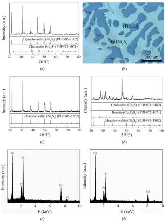
Figure 1(a) shows the XRD pattern of the converter matte used in this
experi-ment. Obviously, the converter matte is composed of Ni3S2 and Cu2S. Figure
DOI: 10.4236/msce.2018.62001 3 Journal of Materials Science and Chemical Engineering (a) (b)
(c) (d)
(e) (f)
Figure 1. (a) XRD pattern and (b) SEM image of converter matte, (c) and (d) XRD pat-terns of Ni3S2 (c) and Cu2S (d), (e) and (f) EDS results of watchet area (e) and mazarine
area (f) in (b).
Two phases with different colors (mazarine and watchet) are observed, the EDS results ofwatchet area and mazarine areain Figure 1(b) are shown in Figure 1(e)
and Figure 1(f), respectively. It is observed that the phase with mazarine is de-termined as Cu2S and the phase with watchet is confirmed to be Ni3S2. In
addi-tion, the Ni3S2 and Cu2S separated from the converter matte were also used as
the starting cathode materials for comparison. The phase compositions of the Ni3S2 and Cu2S are shown in Figure 1(c) and Figure 1(d), respectively. As
shown in Figure 1(d), the Cu2S sample contains a small amount of Ni3S2 and
Cu5FeS4. The chemical compositions of these initial samples (Ni3S2, Cu2S and
[image:3.595.206.539.69.514.2]DOI: 10.4236/msce.2018.62001 4 Journal of Materials Science and Chemical Engineering
Table 1. Table type styles (Table caption is indispensable).
Component Ni Cu S Fe O other
Converter matte 43.77 31.83 18.54 3.24 1.88 0.74
Ni3S2 65.18 4.66 19.57 2.30 6.01 2.28
Cu2S 5.09 67.74 16.66 6.51 3.75 0.25
The schematic diagram of the electrolytic cell used for the electro-reduction experiment is shown in Figure 2. The anhydrous CaCl2 and NaCl were weighed
and mixed at the molar ratio of 1:1. The CaCl2-NaCl mixture was filled in an
alumina crucible (55 mm in diameter, 120 mm in height) and served as electro-lyte. The converter matte was firstly ball-milled and screened to obtain homo-genous powders with particle size below 75 μm. Then, about 1.0 g of the conver-ter matte powder was pressed into pellet with a diameconver-ter 8 mm under a pressure of 10 MPa, the pressed pellet was sintered in argon gas at 400˚C for 2 h. Similar procedures were also used to fabricate the Ni3S2 and Cu2S pellets. The sintered
pellet was wrapped with thin stainless steel nets (pore size of 75 μm) and then attached to a Fe-Cr-Al wire (2 mm diameter) to form a cathode. A graphite rod (12 mm diameter) was used as an anode. The electrochemical experiments were controlled by using a BioLogic HCP-803 electrochemical workstation. Argon gas (99.99%) was used to maintain an inert atmosphere during electrolysis process.
During the electrolysis process, sulphur in cathode may get ionized and transport to the anode, which may cause the precipitation of CaS [6]. A high voltage of 3.0 V is adopted to promote the decomposition of CaS. After being electrolyzed at 3.0 V at 700˚C in molten CaCl2-NaCl for an appropriate time, the
cathode was lifted and cooled in argon gas above the molten salt. Then, the ca-thode was taken out and washed by distilled water. The washed caca-thode product was dried and collected. The morphology of the obtained products was characte-rized by using a scanning electron microscope (SEM, JSM-6700F, JEOL Ltd., Ja-pan) at an acceleration voltage of 15 kV. The elemental composition of the sam-ples was analyzed by using an energy-dispersive X-ray spectroscopy (EDS, Ox-ford Inca, OxOx-fordshire, UK) attached to the SEM and also by an inductively coupled plasma optical emission spectrophotometer (ICP-OES, PerkinElmer Optima 7300 DV, Connecticut, USA). The phase composition of the samples was determined by a powder X-ray diffractometer (XRD, D8 Advance, Bruker, Germany) with Cu Kα radiation.
3. Results and Discussion
The typical current-time curve recorded during the electrolysis process of Cu2S
is presented in Figure 3(a). The current shows a drop within the first 1 h. Then, the current gradually decreases to about 0.2 A at about 2 h. In order to investi-gate the electro-reduction process of Cu2S, the reduction products obtained at
DOI: 10.4236/msce.2018.62001 5 Journal of Materials Science and Chemical Engineering
Figure 2. Schematic diagram of the electrolytic cell.
(a) (b)
Figure 3. (a) Typical current-time curve of the electro-reduction of Cu2S pellet at 3.0 V
and 700˚C in molten CaCl2-NaCl; (b) XRD patterns of the products obtained from the
electro-reduction of Cu2S pellet at 3.0 V and 700˚C for different times.
The XRD patterns of the Cu2S pellets after being reduced at 3.0 V and 700˚C
for different times in molten CaCl2-NaCl are shown in Figure 3(b). It is seen
that the phases of the sample obtained at 1 h include Cu, CaS and FeNi3.
More-over, with the increase of electrolysis time, the peak intensity of CaS decreases evidently. According to the XRD patterns shown in Figure 3(b), copper with a small amount of FeNi3 obtained after being electrolyzed for more than 2 h at 3.0
V. According to the previous work [6], CaS has a low solubility in the salt melt and it will decompose into Ca2+ and S2− as electrolysis proceeds further. S2− will
transport to the anode and then oxidize to form elemental sulphur. The elec-trode reactions for Cu2S may be reasonably considered as:
Anodic reaction: S2– → 1/2S
2 (g) + 2e– (1)
Cathodic reaction: Cu+ + e– → Cu (2)
Figure 4 shows the SEM images of the Cu2S pellets after being electrolyzed for
[image:5.595.213.538.281.422.2]DOI: 10.4236/msce.2018.62001 6 Journal of Materials Science and Chemical Engineering
Figure 4. (a) SEM image of the Cu2S pellet after being electro-re-
duced at 3.0 V and 700˚C for 5 h in molten CaCl2-NaCl, (b) the
par-tial enlarged detail showing the particles in (a).
particle sizes of approximately 20 μm. Meanwhile, the obtained copper particles show rough surfaces and porous structures.
Figure 5(a) shows the typical current-time curve recorded during the electro-lysis process of Ni3S2. As shown in Figure 5(a), the current rapidly decreases
within the first 30 min. Then, the current decreases to a steady value at 1.5 h. The products obtained at different electrolysis stages were characterized by using XRD. Figure 5(b) shows the XRD patterns of the Ni3S2 pellets after being
re-duced at 3.0 V and 700˚C for different times in molten CaCl2-NaCl. The phases
of the sample obtained at 1 h include Ni and CaS. Moreover, with the increase of electrolysis time, the peak intensity of CaS decreases evidently. Based on the re-sult of the XRD analysis (Figure 5(b)), it is suggested that the electrolysis process of Ni3S2 is similar to the electrolysis process of Cu2S, and the reactions
may be expressed as:
Anodic reaction: S2– → 1/2S
2 (g) + 2e– (3)
Cathodic reaction: Ni2+ + 2e– → Ni (4)
Figure 6 shows the SEM images of the Ni3S2 pellet after being electrolyzed for
5 h. Figure 6(b) is the partial enlarged detail showing the particles of Figure 6(a). Obviously, after 5 h electrolysis, the particles presents a complicated struc-ture. Although most of the particles are irregular strips, the dendritic crystals can also be found in Figure 6. The particle size of the obtained nickel is significantly larger than that of the copper obtained under the same electrolysis conditions.
The current-time curve of the electrolysis process of converter matte is shown
in Figure 7(a). Obviously, the current sharply drops within the first 20 min.
Then, the current decreases and reaches to a steady value at 2 h. In comparison with the current-time curves shown in Figure 3(a) and Figure 5(a), it can be seen that the current-time curve of the electrolysis of converter matte is differ-ent. In the initial reaction period, the shape of the current-time curve shown in
DOI: 10.4236/msce.2018.62001 7 Journal of Materials Science and Chemical Engineering (a) (b)
Figure 5. (a) Typical current-time curve of the electro-reduction of Ni3S2 pellet at 3.0 V
and 700˚C in molten CaCl2-NaCl, (b) XRD patterns of the products obtained from the
electro-reduction of Ni3S2 pellets at 3.0 V and 700˚C in molten CaCl2-NaCl.
Figure 6. (a) SEM images of the Ni3S2 pellets reduced at 3.0 V and 700˚C in molten
CaCl2-NaCl for 5 h, (b) the partial enlarged detail showing the particles in (a).
(a) (b)
Figure 7. (a) Typical current-time curve of the electro-reduction of converter matte pellet at 3.0 V and 700˚C in molten CaCl2-NaCl, (b) XRD patterns of the products obtained
from the electro-reduction of converter mattepellets at 3.0 V and 700˚C in molten CaCl2-NaCl.
[image:7.595.210.539.64.209.2] [image:7.595.209.537.267.420.2] [image:7.595.209.536.463.609.2]DOI: 10.4236/msce.2018.62001 8 Journal of Materials Science and Chemical Engineering
Figure 8. (a) SEM images of the converter matte pellet reduced at 3.0 V and 700˚C in molten CaCl2-NaCl for 5 h, (b) the partial enlarged detail showing the particles in (a).
CaCl2-NaCl are shown in Figure 7(b). Obviously, the CaS peaks gradually
de-crease with the increasing electrolysis time, and the phase of the product ob-tained at 5 h is cubic nickel-copper (NiCu) alloy. The reactions of the elec-tro-reduction of converter matte can be expressed as:
Anodic reaction: S2– → 1/2S
2 (g) + 2e– (5)
Cathodic reactions: Cu+ + e– → Cu (6)
Ni2+ + 2e– → Ni (7)
[image:8.595.209.538.69.235.2]Ni + Cu → NiCu (8)
Figure 8 shows the SEM images of converter matte pellet after being
electro-lyzed at 3.0 V and 700˚C for 5 h. Figure 8(b) is the partial enlarged detail show-ing the particles of Figure 8(a). After 5 h electrolysis, the pellet contains large interconnected particles. In comparison with the pure nickel and copper par-ticles produced from Ni3S2 and Cu2S pellets, the NiCu alloy particles are more
uniform and dense (Figure 8).
It should be noted that the electro-reduction process can produce sulphur element and NiCu alloy simultaneously. Considering there are several kinds of metals on the earth are present in the form of sulfides minerals, and the tradi-tional extraction processes are complex. In addition, emission of SO2 is also a
difficult problem due to the increased environmental restrictions. Therefore, the molten salt electro-reduction process may provide a promising strategy for the sustainable reduction of sulfides minerals.
4. Conclusion
The molten salt electro-reduction process has been used to extract nickel-copper alloy from converter matte in molten CaCl2-NaCl. The results show that the
sin-tered solid porous Cu2S, Ni3S2 and converter matte pellets can be electrolyzed to
DOI: 10.4236/msce.2018.62001 9 Journal of Materials Science and Chemical Engineering
and Research Center of Shanghai University for materials characterization.
References
[1] Chen, S., Brown, L., Levendorf, M., Cai, W., Ju, S.Y., Edgeworth, J., Li, X., Magnu-son, C.W., Velamakanni, A., Piner, R.D., Kang, J., Park, J. and Ruoff, R.S. (2011) Oxidation Resistance of Graphene-Coated Cu and Cu/Ni Alloy. ACS Nano, 5, 1321- 1327. https://doi.org/10.1021/nn103028d
[2] Badawy, W.A., Ismail, K.M. and Fathi, A.M. (2006) Corrosion Control of Cu-Ni Alloys in Neutral Chloride Solutions by Amino Acids. Electrochimica Acta, 51, 4182-4189. https://doi.org/10.1016/j.electacta.2005.11.037
[3] Ghosh, S.K., Dey, G.K., Dusane, R.O. and Grover, A.K. (2006) Improved Pitting Corrosion Behaviour of Electrodeposited Nanocrystalline Ni-Cu Alloys in 3.0 wt.% NaCl Solution. Journal of Alloys and Compounds, 426, 235-243.
https://doi.org/10.1016/j.jallcom.2005.12.094
[4] Kear, G., Barker, B.D., Stokes, K. and Walsh, F.C. (2004) Electrochemical Corrosion Behaviour of 90-10 Cu-Ni Alloy in Chloride-Based Electrolytes. Journal of Applied Electrochemistry, 34, 659-669.
https://doi.org/10.1023/B:JACH.0000031164.32520.58
[5] Gonçalves, R.S., Azambuja, D.S. and Lucho, A.M.S. (2002) Electrochemical Studies of Propargyl Alcohol as corrosion Inhibitor for Nickel, Copper, and Copper/Nickel (55/45) Alloy. Corrosion Science, 44, 467-479.
https://doi.org/10.1016/S0010-938X(01)00069-5
[6] Ge, X., Wang, X. and Seetharaman, S. (2009) Copper Extraction from Copper Ore by Electro-Reduction in Molten CaCl2-NaCl. Electrochimica Acta, 54, 4397-4402. https://doi.org/10.1016/j.electacta.2009.03.015
[7] Warner, A.E.M., Diaz, C.M., Dalvi, A.D., Mackey, P.J., Tarasov, A.V. and Jones, R.T. (2007) JOM World Nonferrous Smelter Survey Part IV: Nickel: Sulfide. JOM, 59, 58-72. https://doi.org/10.1007/s11837-007-0056-x
[8] Cameron, R.A., Lastra, R., Mortazavi, S., Bedard, P.L., Morin, L., Gould, W.D. and Kennedy, K.J. (2009) Bioleaching of a Low-Grade Ultramafic Nickel Sulphide Ore in Stirred-Tank Reactors at Elevated pH. Hydrometallurgy, 97, 213-220.
https://doi.org/10.1016/j.hydromet.2009.03.002
[9] Kirjavainen, V. and Heiskanen, K. (2007) Some Factors That affect Beneficiation of Sulphide Nickel-Copper Ores. Minerals Engineering, 20, 629-633.
https://doi.org/10.1016/j.mineng.2007.01.001
[10] Yang, C., Qin, W., Lai, S., Wang, J., Zhang, Y., Jiao, F., Ren, L., Zhuang, T. and Chang, Z. (2011) Bioleaching of a Low Grade Nickel-Copper-Cobalt Sulfide Ore.
Hydrometallurgy, 106, 32-37. https://doi.org/10.1016/j.hydromet.2010.11.013
DOI: 10.4236/msce.2018.62001 10 Journal of Materials Science and Chemical Engineering https://doi.org/10.1016/S0160-4120(02)00064-8
[12] Kojo, I.V., Jokilaakso, A. and Hanniala, P. (2000) Flash Smelting and Converting Furnaces: A 50 Year Retrospect. JOM, 52, 57-61.
https://doi.org/10.1007/s11837-000-0049-5
[13] Moskalyk, R.R. and Alfantazi, A.M. (2002) Nickel Sulphide Smelting and Electrore-fining Practice: A Review. Mineral Processing and Extractive Metallurgy Review, 23, 141-180.https://doi.org/10.1080/08827500306893
[14] Moskalyk, R.R. and Alfantazi, A.M. (2003) Review of Copper Pyrometallurgical Practice: Today and Tomorrow. Minerals Engineering, 16, 893-919.
https://doi.org/10.1016/j.mineng.2003.08.002
[15] Wang, T., Gao, H., Jin, X., Chen, H., Peng, J. and Chen, G.Z. (2011) Electrolysis of Solid Metal Sulfide to Metal and Sulfur in Molten NaCl-KCl. Electrochemistry Communications, 13, 1492-1495.https://doi.org/10.1016/j.elecom.2011.10.005
[16] Chen, G.Z., Fray, D.J. and Farthing, T.W. (2000) Direct Electrochemical Reduction of Titanium Dioxide to Titanium in Molten Calcium Chloride. Nature, 407, 361-
364.https://doi.org/10.1038/35030069
[17] Fray, D.J. and Chen, G.Z. (2004) Reduction of Titanium and Other Metal Oxides using Electrodeoxidation. Materials Science and Technology, 20, 295-300.
https://doi.org/10.1179/026708304225012242
[18] Ma, M., Wang, D., Wang, W., Hu, X., Jin, X. and Chen, G.Z. (2006) Extraction of Titanium from Different Titania Precursors by the FFC Cambridge Process. Journal of Alloys and Compounds, 420, 37-45.https://doi.org/10.1016/j.jallcom.2005.10.048
[19] Schwandt, C. and Fray, D.J. (2005) Determination of the Kinetic Pathway in the Electrochemical Reduction of Titanium Dioxide in Molten Calcium Chloride. Elec-trochimica Acta, 51, 66-76.https://doi.org/10.1016/j.electacta.2005.03.048
[20] Dring, K., Dashwood, R. and Inman, D. (2005) Voltammetry of Titanium Dioxide in Molten Calcium Chloride at 900 ˚C. Journal of the Electrochemical Society, 152, E104-E113.https://doi.org/10.1149/1.1860515
[21] Alexander, D.T.L., Schwandt, C. and Fray, D.J. (2006) Microstructural Kinetics of Phase Transformations during Electrochemical Reduction of Titanium Dioxide in Molten Calcium Chloride. Acta Materialia, 54, 2933-2944.
https://doi.org/10.1016/j.actamat.2006.02.049
[22] Yasuda, K., Nohira, T. and Ito, Y. (2005) Effect of Electrolysis Potential on Reduc-tion of Solid Silicon Dioxide in Molten CaCl2. Journal of Physics and Chemistry of
Solids, 66, 443-447.https://doi.org/10.1016/j.jpcs.2004.06.037
[23] Sakamura, Y., Kurata, M. and Inoue, T. (2006) Electrochemical Reduction of UO2 in
Molten CaCl2 or LiCl. Journal of the Electrochemical Society, 153, D31-D39. https://doi.org/10.1149/1.2160430
[24] Abdelkader, A.M., Daher, A., Abdelkareem, R.A. and El-Kashif, E. (2007) Prepara-tion of Zirconium Metal by the Electrochemical ReducPrepara-tion of Zirconium Oxide.
Metallurgical and Materials Transactions B, 38, 35-44.
https://doi.org/10.1007/s11663-006-9016-z
[25] Kurata, M., Inoue, T., Serp, J., Qugier, M. and Glatz, J.P. (2004) Electro-Chemical Reduction of MOX in LiCl. Journal of Nuclear Materials, 328, 97-102.
https://doi.org/10.1016/j.jnucmat.2004.03.013
[26] Xiao, W. and Wang, D. (2016) Rare Metals Preparation by Electro-Reduction of Solid Compounds in High-Temperature Molten Salts. Rare Metals, 35, 581-590.