warwick.ac.uk/lib-publications
A Thesis Submitted for the Degree of PhD at the University of Warwick
Permanent WRAP URL:
http://wrap.warwick.ac.uk/113595
Copyright and reuse:
This thesis is made available online and is protected by original copyright.
Please scroll down to view the document itself.
Please refer to the repository record for this item for information to help you to cite it.
Our policy information is available from the repository home page.
•riiTBiopr’O T s i'T v.c. m i c kacttintss
D e s i m . construction and rierfornance of
’-ennojient rr.cgnet axial field motors for
traction applications
■by
K . 9. ?T. 41.1
* Thesis submitted to the Fniversity of Warwick
for the degree of Doctor of Philosophy based
unon research condticted in the Department of
Engineering
CCITTEr T9
List of tables
list of figures
Acknowledgements
Gummary
List of nrincipal symbols
1: Introduction
2: Principles of the Machine
3age
U
2.1 Introduction 14
0.? Imnrovinp- Efficiency and
■Performance 19
2.3 Calculation of Magnetic
Pield Distribution in the
Air Gap 27
2.4 ’•'orking Squat ions 36
2.4.1 ETTF Equation 39
2.4.2 Torque Equation 39
2.4.3 Power Equation 40
2.4.4 Relationship between d- and d1 for Maximum
Power 41
2.5 Design Fundamentals of
Permanent Magnet 43
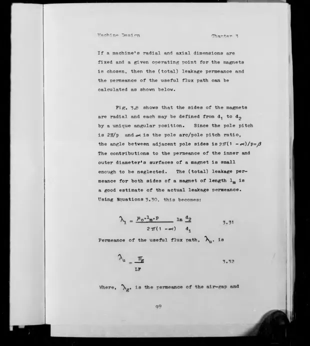
Machine D e s i m 52
3.1 Design Procedure 52
3.2 Design Check *6
3.3.1 Comruter Techniques 73
3.3.2 Software Develonment 77
3.a Ontimine.tion o4" Vachine
Parameters 92
Magnet Behaviour in "Disc Motors 113
4.1.1 t'ornet Tf-3.-teri.al under
Recoi1 Conditions 113
4.1.2 Estimation of Operating Point of Magnet under Recoüî
Conditions 121
4.2 1 25
4.2.1 Analysis of ».mature
°eacti on 1 25
4.2.2 .".mature Reaction
Calculation 148
A. 3 Permanent i'araet stability 1 54
a ^ "z ^ 1 o-*'* ,7oTi‘t'r*o"! 1 1Tiff
Stability 1 55
4.3.^ memrerature Effects
on a Perrite Magnet 153
4.4 T'amet Materials for a Disc
159 ” otor
T'otor Construction and Performance
181 mesting
5.1 Motor Construction 181
5.2 Stator 191
5.3 »m a t u r e 204
3.3.1 The T'ain Winding 204
5.3.2 Equalizer Connections 209
5.3.3 The Resin 215
5.3.4 Mould 218
T j q m n y
1.1 Twin rotor disc armati're motor using
Hycomax 1 1 1 8
1 .2 Twin rotor disc armature motor using
Feroba 111 9
1 . 3 Disc armature generator 1 1
1.4 Single version disc armature motor 1 2
2.1 'Schematic of '^ara^ay's disc 15
2 . 2 Forms of d.c. machine 13
2.3 Shell armature motor 20
2.4 Disc armature motor 22
2 . 5 tminted circuit motor 25
2 . 8 î'oynet volxjme element 28
2 . 7 Pole model 30
2 . 8 Fagnet segment for field distribution 32
?.a Disc armature 37
2.10 W ’.metic circuit of d^ sc armature motor 44
2.11 Demagnetisation and BF versus B curves 49
3.1 Demagnetisation curves under different
temperatures 37
3 . 2 .4 double-layer winding arrangement *7
3.3 Comnuter produced curves 82
3.4 Flow chart of stage one design 87
3 . 5 wiow chart of stage two design 9'
3.* Stator magnet segments 84
3.7 * gar between eoual narallel surfaces 97
5. 8 » gau between inclined surfaces Q8
^ q t?i c w nhaut of tho new comnutar nrogram 108
/ . 1 Estimation of marnet ooeration from ^F
f>Vmi'"ictori sti c
A.2 Coen-circuit magnet oneration against
dimension ratio for cylinders 11 5
A. 3 Pecoii orer^+irir] -Tor materis.ls of low
and hi gh coercivities 11P
A.4 Tvnioal Intrinsic end normal
demagnetisation curves 1 24
A. 5 Magnetomotive force experienced in
traversing line around an amnere turn
source 1 27
A . 6 Samrle section of armature under magnet
133 nole face
4.7 Magnet segment onerating roints after
apnlication of negative m.m.f. 135
00
• Magnet segrrent operating points for
application of positive tr..m.f. 138
A.9 Magnet segment operating points under
load after annlication of negative m.a.f. 140
A.10 Magnet segment operating points after
reversal 147
A.1 1 The airgap flux di stribution 1 45
4.12 1OkW disc motor with eouipment for
recording the airgap flux 147
4.13 Magnet segment mean onerating roints 151
4.14 Change in magnet flux due to temnerature
change 1 6*
i.15 Cren-eircuit voltage against magnet
temnerature at constant sneed for
1OkW disc machine 1 68
4.1 6 Demagnetisation curves of different
material 171
5.1 Production chart of disc motor 184
186
5.2 pOkW twin rotor disc motor
5.3 1 0k'i sing1« version disc moto" 188
5.A Bfc-w disc armature generator 1 90
5.5 The steel cores of the so-'id disc
armature 193
5.6 '''rush ho1 dor ring assembly 185
5.7 Comnonents of 2 0kW twin rotor disc motor 1 96
5.8 The demagnetising characteristic of
Feroba 1 1 1 magnet used in the disc motor 200
5.9 The magnetic circuit test rig and the
flux meter 2 0 2
5.10 Fagnet poles flxed on the flux return
ring 203
5.11 Armature winding 205
5.12 Diagram of a double layer simple lap
winding with equaliser connections 214
5.13 Oeneral assembly of the mould 219
5.14 The steel mould 2 2 1
5.15 Solid disc armature 226
5.15 Skeleton armature 229
5.17 Diagrammatical layout of the test rig 232
CD
• D.C. induction machine set used to feed
power to the mains 233
5.19 D.C. load machine and torductor ring 234
5 . 2 0 D.C. generator - induction motor set
used to suprly nower to the test machine 236
5.21 Torque motor calibration 238
5 - 2 2 Hand tachometer 240
5.23 Heat soy infrared thermometer 242
5-24 Heat spy thermometer block diagram 243
5.25 Stator magnets with wooden wedges
between noles 245
5.26 wo load test 247
5.27 Performance curves of 1 Okv motor at 2A V 249
5.28 Performance curves of 10kV motor at 48 V 250
5.29 Performance curves of 10k'v' ’''tor at 72 y 251
5.30 ‘rerform«nce curves of 1 ovw motor °t 86 V 252
ge
5*31 Fredicted nerformance curves of 1 0k'-/'
motor 254
5.32 Reinforced armature winding
5.33 Skeleton armature cores 258
5.34 '’’emnereture rise-time curve of skeleton
armature 262
5.35 Rddy current induction in a metal slab 26 5
5.3C Calculation of eddy current in conducto—s 26Q
5.37 Cond” otor in airgao 274
5.38 Armature conductors in stranded form 276
5.3Q Dummy poles (wooden) 280
5.40 Skeleton armature with no eoualiser
connection 281
5.41 Open-circuit voltage - sneed curve of
the 1 0kW disc machine nan as generator 282
5.42 Incut power sneed curves of the loading
machine when driving 1 0kW disc motor 283
6.1 Drive system of the electric car 290
6.2 Drive system of the series hybrid car 292
8 . 3 Drive system of parallel hybrid car 294
6.4 Floor nan, chassis and body of Fova car 305
8.5 The Dragonfly u ovgi 307
8.£ Weight distribution and centre of
gravi ty improvement 309
8.7 The twin rotor disc motor and its
associated belt reduction gears 310
8.R Drive system of the Dragonfly "ova
hybrid car 31 3
8.Q Diesel engine - d^sc generator 318
8 . 1 0 ■Rower circuit - M cva car 319
a ekn owl o d .TOTHf? ri t g
T would like to express my thanks to the
following;
To my wife for her continual sunport and
encouragement and my children for their smiles
and cheerfulness In times of stress.
To my Academic Supervisor, Fr. A.E. Corbett,
for his encouragement, assistance and patience
throughout my period of study.
To my friends for their academic support,
nanticularly Chris Roerig, Colin Anscomb and
Selami Edylemez.
To all members of the Engineering D<" nartment
Workshop for their assistance with construction
of the m^tor. particularly Fr. David Thompson.
To Mrs. Penny Mead for converting my
manuscript from Arabic English to English English.
To Fr. Michael G. Gould for his photographs
which have brought my thesis to life.
Finally, to the many others, too numerous
to name here, who have willingly given my their
help and novice.
\ r i e l — f i e
"
1
* r Tv-ianC n+ jno -rrie+ m o to rs heVCqVlr)..rP ■♦jo 0*T^P*o ♦ |r>-~>,(..Trp ^ o -P-*M (* -f pin (JV (arid
r>o’-»e»* d e n si t y cop ^ " r f;'i v *t h co n v e n tl o w
1
m a ch in es.mVi o i^i ffo>»or>+ *i3"c'?+R o-f -tjV*q edv^pb o fr&Q o-f ▼.cpr-qn qpb -io~r>ot ^sr> q-omotv-oo motors h^ve boon demonstrated.
5 technioue is described by which the magnetic circuit is then desimr.ed for optimum motor efficiency. The development of criteria for the selection of machine parameters leads to a commuter program that
produces a realistic design given only the desired
rower, speed, and voltage as innut data. An
s.nalytical model has been established to quantity vely predict the degree to which the permanent magnet field is demagnetised by the armature current.
A new method for armature construction (skeleton armature) is described which is more satisfactory than encapsulation for the necessary mechanical strength and rigidity.
The high power to weight and high power to volume allows novel locations to be considered for the drive motor within the vehicle, and a new design of axle-mounted twin-rotor machine will also be
described. Such relocation, together with belt
reduction gear, reduces the weight and rower losses associated with otv er transmission components.
The constriction of a vehicle test facility to evaluate the performance of electric and hybrid
vehicles is described. The Nova series hybrid
vehicle was tested on the rig. The trials showed
Lis-*; o■P ■Principal Symbols
Symbols represented as strings of capital
letters usually refer to those used in a computer
crop-ram or associated output.
a number of parallel paths in a
D .C • machine
A brush contact area
Ac specific electric loading
, ALPHA ratio of pole arc to pole pitch
ARPCRT armature current
Bi.j flux density at position (i,j) in
color co-ordinates
Bra, BY magnet flux density
Bw magnet flux density at working
temnerature
Bs mnvnet flux density at sub-zero
temnerature
B-** remanance on demagnetisation curve
0. CRTDSY current density in armature conductors
CB battery capacity
°D vehicle drag coefficient
C c ,COILS number of coils in a D.C. machine
^ ,D1 inner active diameter of disc armature
motor
d2,B2 outer active diameter of disc armature
motor
efflciency
r? f?Tf
J » • * renerated e.m.f.
-1 tyre rolling resister.ee
7 2 aerodynamic drag
"PRR flux return ring
G , G iTOR gauge of wire used in armature
n * r magnetic air pap length
t,F qinp force in airgap
W m . r *» 'metising force in magnet
T (sr^eture; current
T . T VY number of layers of armature conductors
T o _ trjpyPT? leakage coefficient
IF.T'PiC'!’ loss factor
IS length of magnetic airgan
lr>. Tm ».C 1»nrth of me.gnet
Tpop electrical losses in disc armature motor
M»GDSY density of magnetic material
KRCHLC mechanical loss
V
■ V mass of road vehicle
/*0
nermeability of free space
H r relative permeability
n rotational sceed, rev/min
w rotational speed,
p.ROIRS number of Doles in a G.C. machine
rower outrut (mross)
■PA'nJiJ number o^ nara‘,l e l raths ■'n a "O.G. machine
A.^FT flux ner no*1 e
nVPv,G m +4 n of •noto1" ro,T°r to motor we-’f+it.
rower densi ty
density of air
P
p p a p y a'' r 1 r 2 «JV T THTCF m ‘r TURNS TCTWCT ▼ V V b W<xT1?RR WGTKA.G
VGTr A.P
WGTVIR
z. 7
resistivity of confer,
armature resistance
inner active radius of disc armature motor
outer active radius of disc armature motor
snace factor
mechanica!! toroue
armature temperature at which motor performance is calculated
thickness of flux-return ring
rated toroue
turns per coil
total weight of motor
speed of road vehicle
voltage
brush voltage drop
weight of flux-return ring
weight of magnet
weight of"non-active parts"
weight of copper used in arroatu winding
mechanical loss
eddy current loss in armature Conner
number of conductors in an armature
ideal number of conductors
didn't«!* 1 Introduction
Oil is running out. It will not be Ion*"
before this, one of our cost orecious assets,
will pass its sunuly neak and will start to
decline in available volume.
It has cowered the greatest technological
revolution in history; it is the life-blood
of the manufacturing and transport industries,
and factors other than short-term commercial
interests should decide how remaining supolies
are used.
In 1973, OPEC countries took action to
conserve oil to ensure that future generations
are not left without, and this action will be
increased by both producers and consumers
during this next decade.
i full study1 of the problem of reducing
petrol consumption shows that it is in the
transnort sector, in narticular road transport,
(where 79^ of the petrol is used), that the
largest petrol saving will be made.
The goal of reducing the amount of
netroleum demand in road trensnortation. can
Introduction Charter 1
he achieved by transferrin? some of the
demand to more plentiful energy sources such
as coa1 or nuclear sources. Dlectric
vehicles can satisfy this requirement
because all their energy needs may be
obtained from central electricity rower
stations which may use these alternative
fuels. however, the energy advantage of
electric cars is obtained at the expense of
several performance characteristics. Range
acceleration, hill climbing ability and
usually maximum sreeds are reduced compared
with those obtained by conventionally
covered vehicles.
A hybrid vehicle which uses two sources
of energy has the potential of reducing
petroleum dependence to a lesser degree than
an electric vehicle but its performance is
more like the conventional vehicle than that
of the poorer nerforming electric vehicle.
Furthermore, the hybrid vehicle can still
ooerate as an all-electric vehicle, but at
lower -performance levels. TTntil recently,
hybrid vehicles were designed to reduce
Tntroducti on C h a r t e r 1
consumption. However, the present interest
in hybrids is because of the reduction in
on-board petroleum consumption. Therefore,
nowadays hybrid vehicles have been designed
to serve as transitions between conventional
and the all-electric vehicle. Thus,
manufacturers of certain hybrid vehicles
will allow a gradual change-over in
manufacturing processes. As progress is
made, these hybrids will be built with smaller
and smaller engines and will use batteries of
gradually increasing capacity. Hence, the
hybrid vehicle is essentially an all-electric
vehicle loaded with an ideal battery system
which, in this case, is represented by the
on-board engine generator set. Therefore,
the engine generator is a temporary solution
until the promised breakthrough in
traction-battery design occurs.
The impression thus gained, is that the
only current problem is the development of
a high performance traction-battery. This
i3 inaccurate because the existing electric
T ntroducti on Chant ° 1
production vehicles, varions experimental
vehicles and conversions of conventional
vehicles. The component ouantities
renuired have not been sufficient to
iustify extensive development by manufacturing
industry. Consequently, designers have had
to adant and modify equipment that was
originally not designed for electric and
hybrid vehicle anplications. This is
particularly true for nronulsion systems, whil<=
electric motors having sufficient cower for
electric and hybrid vehicles were designed
for industrial applications for which weight,
size, and part-load efficiency are not
critical factors, and for which considerations
such as long-life are more important than
initial cost. As a result, available
traction motors ar° expensive, inefficient
at low rower levels, their power density is
not optimised, and transmissions are designed
around the operating parameters of petrol
powered engines. The result is that
propulsion systems found in existing electric
and hybrid vehicles are characterised by
performance below theoretical expectations.
Introduction Charter 1
The need is thus demonstrated when considering
the design of any new electric and hybrid
vehicles of not being restrained by having to
use existing I.C.3. vehicle components.
However, it is economically much more viable
to take as the basis for an electric vehicle
some I.C.E. vehicle for which mass production
capabilities are already available.
This conflict of requirements is overcome 2,3
at Warwick University, by developing a disc
motor and transmission that is efficient and
will also fit into an existing I.C.H. vehicle
chassis with the minimum modification.
4,5
Development of the axial-field, permanent
magnet, DC disc motor has demonstrated sig
nificant improvements over conventional
machines in terms of efficiency and power
density, giving the machine good potential
for application in electric and hybrid vehicles.
Furthermore, the short axial length and high
power/volume ratio of the machine facilitates
the design of compact traction systems.
The essential difference between the DC
disc motor and Its conventional counterpart
Introduction Chapter 1
lies in the disposition of the active con
ductors and the working magnetic flux: in the
disc motor the magnetic flux is parallel to
the shaft and the active conductors are per
pendicular to it. This configuration lends
itself well to high pole number designs, and
the heavy steel yoke of conventional machines
is replaced by thin-aection steel flux return
rings and a light alloy frame.. Using permanent
magnets it is practicable to employ a coreless
armature construction which further promotes
weight saving and means that no iron is
subject to varying magnetic flux. The absence
of iron losses and elimination of the require
ment for excitation power are both helpful in
the quest for h igh efficiency.
A twin armature disc motor with differen
tial action has been developed for the drive
of an experimental hybrid snorts car. This
machine comprises a common magnetic circuit
which houses two disc armatures, each
armature mechani cally driving an independent
output shaft which t~'>nsraits power to a road
wheel through belt-reduction gearing, thereby
Introduction Charter 1
eliminating the need for a mechanical
differential gear. The twin armature motor
and belt reduction pears have been carefully
designed to fit within the limited span
between the two road wheels in the space
usually occupied by the differential rear
axle drive.
Figure 1.1 shows a disc motor employing
magnets of the alnico type (Hycomax III).
Specifying Hycomax III allows for a moderately
big^1 air-gap flux density which leads to very
hiph motor efficiency. Unfortunately the
cost of alnico material has increased quite
dramatically durinp the course of the project
owing to a large increase in the world price
of cobalt, and it is considered that building
a traction motor using magnet material of
this tyne will not become widespread in such
an arrlication.
In contrast, the cost of ferrite materials
is low enough to make its use viable in spite
of its low remanence and energy density. For
this reason, a machine using ferrite magnets,
as shown in Figure 1 •9 has been developed.
Significant savings in weight and cost result
[image:25.641.3.626.11.708.2]Introduction Chapter 1
from adopting- the twin-rotor arrangement rather
than two separate motors. The vehicle also
employs a disc-armature generator having many
parts which are common to the motor, as shown
in Figure 1 -3.
The development of criteria for the
selection of all machine parameters has made
it beneficial to reappraise the design methods
available and hi ghlight aspects of design and
performance peculiar to this type of machine.
The principles of the machine have been
studied at great length and comparable
attention needs to be paid to the magnet
behaviour of the machine especially when
applied to electric traction. There have
been no reliable methods of determining the
losses involved and their relationship to
the performance of the machine. This is an
aspect which required extensive investigation.
Although illustrated here for this novel
topology for application as a traction motor,
the procedures and criteria described could
eoually be applied to the design of motors for
rr 1 # ■*. . Tl-jof. KrT««+1JT>í» r- onf” 1" ♦oi'
Charter 5 Principles of the ’’sc'-in°
1 Tntroducti on
The axial field DC machine is one of the
first machines devised to convert electrical
power into mechanical power. Its origin can he
traced to disc-type machines conceived and
tested by Michael Faraday, the experimenter who
formulated the fundamental concepts of electro
magnetism. The machine was a copper disc
rotated by a spindle in an axially direc+ed
permanent-magnetic field, with sliding contacts
(brushes) at the edge and centre of the disc,
for introducing and/or picking off electrical
power as shown in Figure 2.1. Faraday's
primitive design was quickly improved, and the
multipolar version, in which a winding is rotated
in the magnetic field of successive N-S pole-pair,
soon followed.
In recent years, the use of DC machines has
become almost exclusively associated with applic
ations where the unique characteristics of the DC
motor (e.g. high starting torque for traction
motor application) justify its cost, or where
portable equipment must be run from a DC (or
battery) rower supply.
The ease with which the DC motor lends
itself to speed control has been recognised.
Compatibility with the new thyristor (SCR) and
transistor amplifiers, plus better performance
due to the availability of new improved
materials in magnets, brushes and epoxies, has
also revitalised interest in DC machines. The
need for new high-performance motors with highly
sophisticated capabilities has produced a super
abundance of new shapes and sizes quite unlike
DC machines of a decade ago.
Most industrial motors have multipolar
field systems and a cylindrical shape. There are,
however, several other possible forms such as the
disc, the linear and the tubular. Further, the
homopolar field arrangement (the type of machine
built by Faraday) has been developed to provide
large current at low voltage for electro-chemical
processes. The homopolar shape lends itself to
the use of superconducting field windings, by means
of which very high working flux densities can be
achieved. But whatever the topology of the
machine, and be it homo- or multi-polar, the 1
1 *
Principles of the Machine Chanter ?
f
essential requirement is that a current flows in
a direction at right-angles to that of the flux of
a permanent or electromagnet in such a way as to
utilise most effectively the mechanical force
developed hy flux— current interaction. The
relation between the cylindrical, disc and linear
forms is brought out in Figure 2.2 in terms of
the conversion region, i.e. the gap between the
fixed and moving members. If the cylindrical
gap region (a), shown with its d- and q- axes
and armature current directions, has its front
radius contracted and its rear radius expanded,
it becomes the disc form (b); and if, instead,
it is cut axially and ’unrolled' the result is
the flat linear form (c); and finally if (c) is
're-rolled* into a tube, the linear tube shape
(d) is obtained.
T'rirciT)!! es of th° Machine Chapter ?
Frinei es of the Machine Charter 2
^ ? I m p r o v in g E f f i c i e n c y and P erform an ce
In DC motors, power is wasted due to losses
associated with the iron core. In conventional
designs, these losses are reduced by laminating
the rotor core, thus elimination of these losses
must serve to increase the motor efficiency.
Furthermore, for traction applications, operation
at hi$i efficiency over a wide load range is
necessary with high power/weight ratio. Meeting
these requirements has been accomplished by a
variety of designs. Maximising the developed
torque and power of the conventional DC machine
by use of the new magnetic material has been one
method of approach, whilst other types reflect
more fundamental changes. Amongst these latter
types are those having an iron-less rotor con
struction. Elimination of all iron losses in
this type of motor is accomplished by combining
all of the iron structure with the permanent
magnet assembly, so that the flux return circuit
is stationary on the remote side from the magnets,
and inserting the core-less armature conductors
P
ig
.
2.
3
:
Sh
ell
ar
m
at
ur
e
m
ot
The iron—less (or moving coil) structure
design of the present era has followed two
general paths: the flat disc armature and the
hollow ("shell" or "cup") armature. The two
structures are shown in Figures 2.4 and 2.3.
Both units have a multitude of conductors which
move in a magnetic field. The armature struc
ture is supported mainly by non-magnetic
materials and the active conductors are therefore
moving in an air-gap with a high magnetic flux
density.
The shell-type armature (Figure ?-3) consists
of a cylindrical, hollow rotor which is fabricated
to form a rigid shell structure by bonding copper
or aluminium coils or skeins by the use of polymer
resins and fibreglass and other structural members.
This method offers considerable flexibility in
design since the manufacturer can offer a variety
of wire sizes, turns per coil, and diameter and
length options.
Due to the unique construction of shell (cup)
armature motors which is fixed at one end to the
Principles of the Machine Charter 2
cylindrical commutator, and since plastic parts
deflect under torque, the instant velocities of
various parts are different, which results in
angular vibrations which may cause problems to «. 7
the user. This phenomenon has the effect of
limiting the size of this type of motor to under
one horsepower. It is found that the cylindrical
shell construction of the armature has low
mechanical stability, and this limits the overload
capability considerably. It is considered that
it may not sustain the environmental conditions
particularly shock and vibration required in
road traction especially if subjected to any
emergency overload.
This conflict of requirements is overcome
by developing a new motor. This new motor is
an axial field DC machine, with a permanent
magnet field system. The disc armature motor
differs from other axial field machines primarily
in respect of its rotor's construction. The
active conductors lie radially, and the
wire-wound coils are arranged in various ways to give
a convenient number of layers. This is
traditionally any even number.
The coils sind commutator are given
mechanical, rigidity by encapsulating in epoxy
resin (Figure 5.15) or wranring with heat-curing
glass-fibre tapes and dipped in varnish to give
a "skeleton" construction, but since no iron is
included in the rotor, an air-gap length of a
few millimeters results. This, however, is
easily overcome by using permanent magnets of
relatively high coereivity.
There are many advantages that result from
this particular motor design, and most sire found
to be desirable in the electric vehicle application.
There being no iron in the armature, there will
consequently be no core losses. Bearing losses
also are very small since there is no thrust
force. The efficiency of the disc-armature
motor can therefore be very high, dependent upon
the copper losses of the armature winding, and
hence upon the motor's designed operating voltage
and speed.
Princinles of the T’achine C h a p t e r ?
Bearing
Printed circuit armature
Brushes Kagnet poles
Fagnetizinr winding
Principles of th<= Machine Charter 2
The topology of the disc-armature motor
shown in Pig- 2.4 is similar to that of the
printed circuit machine shown in Figure 2.5
However, in the development of this new machine,
modelling of the magnet system has produced a
design that gives a much improved flux per pole,
using poles shaped as segments of a toroid
(Figure ?.4> • It is especially important to use
an accurate model of the permanent magnet materials
to achieve optimum performance of this type of
machine, due to its unusually large air-gap. It
is also particularly pertinent to use new designs
of a machine based upon such a model, since these
more advanced magnet materials are most often
directly substituted for older types in conventional
machines, with the result that their superior
properties are not fully utilised.
That the disc— armature motor's pole design give;3
increased pole surface area than that used in most
printed circuit machines is not the soie di^f^reree
between the two. The more conventional winding
of the disc armature motor allows it to sustain
normal traction and overload currents, conditions
under which printed circuit motors have frequently
^ r i n c i o l e s c ‘p t h e M a c h in e Oh 0.T “t 0 T* ^
?.3 Calculation of Magnetic Field Distribution
in the Air Gan
More often the designer requires to calculate
the field and possibly the field gradient produced
by the magnet at some point outside the magnet or
in a gap.
In theory magnets were regarded as made up
of many tiny current loops. The atomic view of
the origin of magnetism is very important
theoretically, for understanding the behaviour
of magnetic materials, but for calculating
external fields, continuous models usually suffice.
The most realistic model is to suppose that
each element of volume dv inside the magnet
constitutes a magnetic dipole which has a dipole 0
moment Jdv, where J is the average polarisation
within the element. According to elementary
magnetostatics, the potential at a point P at
distance r meters from this dipole, in a direction
defined by an angle 6, as shown in Figure
= J. cosP.dv 1
4 7T. p Q. r2
P
0
/La__ / /
'0 e-
/-*’“/T
d V
Vapnat volume element
.•
a
w
>
.
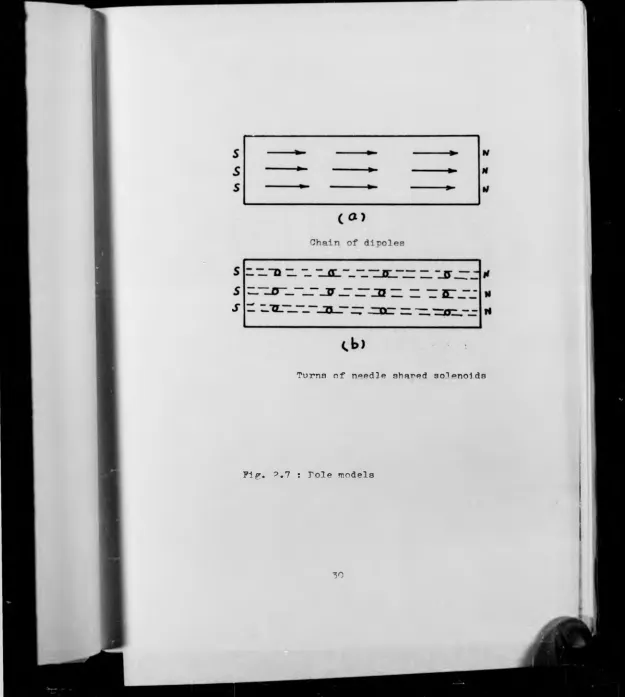
Turns of needle shared s o ^ nolds
Fig. ?.7 : Foie models
[image:49.653.7.632.12.709.2]Principles of the Machine Charter 2
in a e^ain (Figure 2.7.a) the M nole of one dioole
neutralises the S role of the next, and only one
tt role and one S role are left at the ends of the
chain. The same concept arises Just as naturally
from current loops (Figure 2.7.b). Fach current
loor is regarded as one turn in a long thin
solenoid. A long thin solenoid is enuivalent
to a needle shared magnet with an IT oole at one
end and an S pole at th° other. Therefore, it
is auite suitable to treat a magnet. whicv' is
made in homogeneous materials, as havinr a
uniform distribution of poles on its end
face-plan i.e. the surface pole strength, J, has a
constant value on the magnet's face, and is
zero on its sides. This is a reasonable
approximation for the high-coercivity anistropic
magnet used in disc armature motor applications,
where the direction of magnetisation is along the
normal on the magnet face-plan. As stated above,
the role strength on area dA on a surface whose
normal makes zero angle to the direction of the
surface rolarisation. is J dA. Then the
potential at distance r from such a small element,
as shown in Figure ?.B is:
Princirles of the I'aehine C h a p t e r 2
in a c^ain (Fieure 2 . 7 .a) the TT role of one dirole
neutralises the 3 role of the next, and only one
n role and one S role are left at the ends of the
chain. The same concept arises just as naturally
from current loops (Figure 2.7.b) . Fach current
loon is regarded as one turn in a long thin
solenoid. A long thin solenoid is eauivalent
to a needle shared m a m e t with an F role at one
end and an S pole at th° other. Therefore, it
is m i t e suitable to treat a magnet. whic^ is
made in homogeneous materials, as having a
uniform distribution of noles on its end
face-plan i.e. the surface pole strength, J, has a
constant value on the magnet’s face, and is
zero on its sides. This is a reasonable
approximation for the high-coercivity anistropic
magnet used in disc armature motor applications,
where the direction of magnetisation is along the
normal on the magnet face-plan. As stated above,
the role strength on area d.A on a surface whose
normal makes zero angle to the direction of the
surface rolarisation, is J dA. Then the
rotential at distance r from such a small element,
as shown in Figure is:
^rea element
?ifr. ?.8 : Yafmet segment for field distribution
n d r]pfj of t b o Ohpr. +,**■»*» p
J
?.3
4 ^ 7 V r
and the magnetising force H is given by the
following differentiation from Equation ?.3
If only the axial direction is considered,
integration over the whole pole face yields
Where ^ is the angle between the normal at m-’PT.^t
a-r^ace and "the line joining dA to point P. To obtain
B in Tesla multiply by fiQ and so eliminate jxQ
from the denominator.
The armature winding is formed in discrete
layers, each lying in a radial plane in front of
the pole's face. If the winding is reduced to
H J_____
ar 4 7T.yo .r?
2.4
H
X J. cos $ dA 2.S
■principles of the T'achine Chapter 7
o
indivi dual conductors, and each conductor to
elements that lie in such a plane at radial and
angular positions denoted by subscripts i and j,
Complications arise in the pole method, when
problems with non-uniform magnetisation are met,
since the poles can no longer be supposed to be
situated on the surface of the magnet.
The advantage of replacing dipoles with
poles is that the field due to dipoles obeys an
inverse cube law, and depends on the angle
between the direction of the dipole and the line
joining it to the point at which the field is
required, while the field due to a pole obeys a
simple inverse square law and is directed along
the line joining the pole to the point. So,
the significance of Equation 7. .6 is that the field
then the air-gap flux density ^ in the axial
r rinci r>] eg of the Machine C h a r t e '* ' ?
in the air-gap can be calculated without
reference to a potential distribution on the
pole face. The magnet polarisation J exists
only on the pole face and is not dependent
upon radial or angular position. The draw
back to Equation 2.6 is that the remaining
integration can only be performed by numerical
means, and it will only be possible to find a
discrete field distribution. Modern computers
have made numerical integration a reasonable
proposition and the method is probably the most
promising one for estimating the fields produced
externally by magnets in which J, has uniform
and known distribution.
■Principles of the t’aohine
? .4 nr Fnuatinns
2.4.1 BMF Equation
The disc aT-ature, Figure 2.9 of effective
outer and inner diameters d2 and d 1 , rotate in
an average air-gap flux density B at angular
speed w. Consider an element of armature
conductor of radius r and radial length dr.
It moves at peripheral speed w.r and its
motional EMF is:
The conductor EKF between diameters d2 and d1
therefore:
If Zg are the number of conductors in series
between the brushes, so that
de = B.w.r.dr 3.7
2 . 8
ncinles of th® v acv,1n<> Charter 2
Where a is the number of parallel paths throu^i
the armature and Z the total number of armature
conductors. Thus:
Where 3 is the total armature 3MF. Equation 2.10
is often the most useful for determining the
3MP generated in a disc armature machine.
However, the flux per cole. 0, may be written
as:
Where p is the number of poles. Therefore, the
BMP may be expressed as: S = 1 E.w.Z.(d| - d?)
8 a '
2 . 1 0
S* = ^ .IT.
2.11
4 p
2 . 1 2
2 IT. a
But
w 2 rr.n ?. 1 3
I
T rincinles of the Machine Charter 2
Where n is the rotational speed in rev/min.
Thus:
E = 0. p . n . 7.
^0 a
2.14
Equation 2.14 is the familiar EfT equation for a
d.c. machine.
2.4.2 Torque Equation
If the armature conductor carries a current
of Ic , the interaction force on the element dr
of the conductor is:
dP = B.IQ .dr 2.15
Developing a torque
dT = B.T .r.dr
c c 2.16
Where T^ is the torque due to a single armature
conductor. Equation 2.16 integrates between the limits
d^ and d^ to give:
Tc =i (dl -
AV* Tc
2.17y- r j ■ nl o3 oi* ■+;Vio T"i? o h in o V -p ru -v* O
T
T>veT.of^7-o ^duoti on "5.17 becomes:
2.19
ind tbe total armature torque, T is:
T = — ( d£ - d2) 3.I.Z 2.20
P d ' a
2.4.3 r ower Pcuation
It can be shown easily that the converted
power of the electric motor (including disc
motor), P, is:
P = T.w 2.21
Substituting for T from Bouation 2.20
T'rinciples of the ’’achine Charter 2
P = - (di; - d?' ^.-.S.-r 2.?2
P £ a
Tot ! he the s u e d fi c ei ectri e loading. i.e. c
q^Tipre-cnninoto1” divided hy motels of ornature
wind: np- at radius d^ , therefore:
2
Ac
V 7'
7T.d
1
T .5
a .7y. d ^
2.23
Substitute for T air^ w in Fouation 2.22 from
Fouation 2.25 and 2.13 thus:
J ^ . A .n.(d| - d?) d.
r = H --- 2--- 1---- !--- 1 2.24
240
2.4.4 Relationship Between d? and d1 for
Maximum T’ower
From Fouation 2.24 nower can he written as
P = k(d| - d^) d 1 2.25
■'’rinci nles of the Machine Chanter 2
And this is zero only when:
4
= 3 d* 2.27and = - 2 2.28
Substituting in Equation 2.24:
1 6 0 0
Thus the power output available from disc
armature motors is aporoximately proportional
to the cube of the outer active diameter.
Frincinles o f the T'achine Chester 2
^ Design Fundamentals of Permanent Magnet
In this section the basic concepts of
permanent magnet design along with some specific
information on their applicability to axial
field machine configuration are set forth.
The designer of magnetic circuits should
normally aim to produce the required flux in the
air-gap at minimum cost. Since permanent
magnet material is much more expensive than the
type of soft iron or mild steel used in
permanent magnet assemblies, minimising the cost
is often equal to minimising the volume of
permanent magnet used.
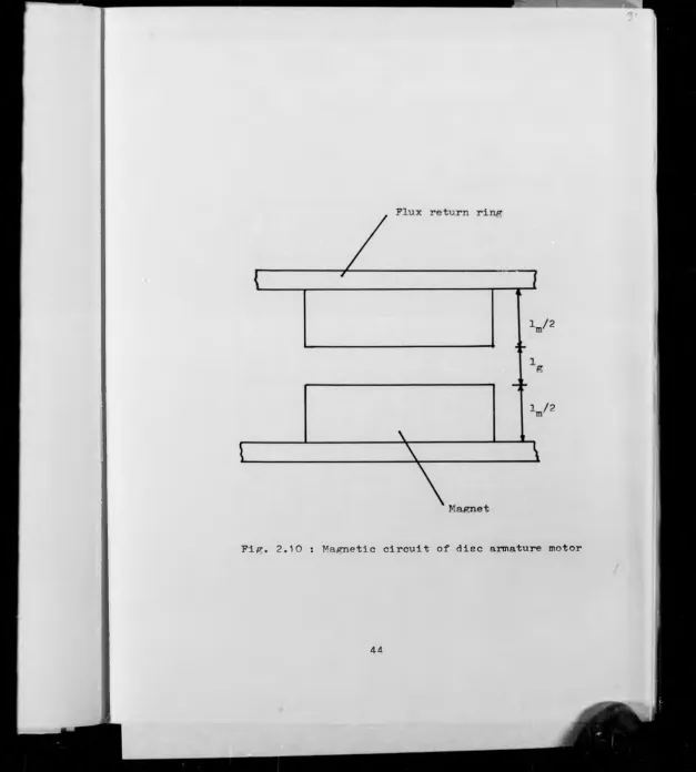
Fig. 2 .10 shows part of a typical magnetic
circuit (for a disc armature motor). It consists
of two permanent magnet halves with total length
lm, two mild steel return rings and a relatively
large air-gap, lg, which accommodates the total
armature thickness with suitable running
clearances between it and the pole faces.
[image:63.661.26.635.14.713.2]Fig. 2.10 : Magnetic circuit of disc armature motor
[image:64.668.21.648.15.711.2]Principles of the T'achine C h a n t e ” 2
magnet is equal to that exoended across the
air-gao, i.e. the total magnetomotive force
in the circuit enual to zero. This theory
is true only when using a correction factor,
LF, the loss factor, which accounts for the
mmf lost in the reluctance of any joints or
in any steel parts of the circuit that cannot
be regarded as having infinite permeability,
therefore:
Hm.Lm = LF.Hg.lg 2.30
Where Hm and H g are the magnet and air-gap
magnetising force. The value of the loss
factor, generally varies from 1 . 2 to 1.3
and it requires some experience to estimate.
On the other hand, the flux in the permanent
magnet material is equal to the sum of the
flux in the gap and the leakage flux, which is
wasted because it returns by some path other
than through the gap. Consequently, the per
manent magnet flux density, Bm, is greater
than the air-gap flux density, Bg. This
^rincirles of the Vachine Chanter 2
a leakage coefficient. LC such that:
Bg = Bm 2.^1
LC
The leakage coefficient, LC, is generally
rather difficult to evaluate. The specific
case for disc armature motors is covered in
Section 3.4. Now, since by definition:
H g = 2.32
^ o
Therefore, from Equation 2.31 and 2.32, air-gap
magnetisation becomes:
H g = 2 *^3
LC ^ o
By substituting for H g from Equation 2.33 in
Eouation 2.30. lm becomes as:
LF.Bm.lg
lm = --- 2.34
LC. jiq. Hm
Eouation 2.34 comnletes the calculation of
magnet length. This concludes the first part
of the design problem.
In «baling with nermanent magnet design,
interest is centred only on the demagnetising
curve. Fig. 2.11 shows the demagnetision
curve of a permanent magnet material having
previously been fully magnetised. On the
right hand side of Fig. 2.11 a product of Bm
Hm has been plotted against the value of B.
There is one particular working point on the
demagnetisation curve for which the product
BH is a maximum. This maximum is referred
to as (BH) maximum and is a useful character
istic of the material. It has the dimensions
_*3t
of energy per unit volume (Jm J) and is
generally called the maximum energy product.
If the values of Bm and Hm corresponding to
the (BH) maximum are used in determining lm,
the design will also be for minimum magnet
volume.
Now, if the term Bm of Equation 2.34 is
Kin
Frincio} es f the T'achine Chapter 2
[image:67.662.16.645.12.700.2]^rincinles of the Rechine Charter 2
algebraically expressed as a function of lm
and lg with a constant of proportionality
LC jxQ , then Equation 2.34 becomes as:
LF
_ ££ ^ o . — 2 . 3 5
Hm IF lg
For the specific design of DC disc motors
LC approaching to unity, then Equation 2.35 can be
LF
written:
M = P0 2“ 2.36
Hm lg
This equation shows how to design a magnet with
the correct length so that it will work at the
optimum (BH) maximum point, which is given by the
intersection P of a line OA of slope defined by
Equation 2.36 and the demagnetising curve in Fig. 2.13.
Incidentally, given the demagnetisation curve,
the (BH) maximum point can be quickly approximated
■PiR. 2.11 : Demafmetization and BH versus B curves
/
^rincinles of T'achine
Br and He points to intersect at A forming
a rectangle A Br 0 He. The diagonal OA of
this rectangle is approximately the unit
permeance line given by Bouation P.36. This
construction is not nuite accurate but gives
a very good approximation to (BH) maximum.
In a practical design, there may well be
other factors as well as minimum magnet
volume to be taken into consideration as
discussed in Chapter A , It must
be stressed that this discussion relates to
a magnet assembly that is magnetised to
saturation after assembly and is not subjected
to permeance changes or to substantial current
m.m.fs under working conditions.
It will be noted that the factors which
determine the load line slope are geometrical
and are dependent on the size and disposition
of the magnetic circuit but are independent of
the demagnetisation curve, thus working values
of Bm and Hm for another magnet material with the
same dimensions and disposition would be given
Principles of the T'achine Chapter 2
by the intercept of the same load line with
the new demagnetisation curve. 'Che application
of this single load line to the whole volume of
permanent magnet material is usually a reasonable
approximation with magnets of modern material
with uniform cross-section and flux-Path length.
From the above discussion, it is evident that
the minimum volume of magnet material to fulfil a
motor specification is obtained by a design in which
the magnet working points are at a point on the
demagnetisation curve for (BE^ . But, as
mentioned earlier, the desirable working point is
likely to be higher than Bm for (BH)max due to
secondary considerations, e.g. with ferrite magnets,
protect'on against sub-zero temperature changes and
dif^-'culty in producing and utilizing optimum
Chanter 3 Machine Design
3.1 Design Procedure
In order to design a d.c. axial-field
permanent magnet motor, one needs to know the
output power reauired. the operating voltage,
the speed specification and the choice of magnet
material. Having specified these, a suitable
starting point for the design procedure would
be to consider the diameter of the machine.
It has been shown in Chapter 2 that the
total mechanical power from a disc armature
motor is proportional to the cube of the
diamater and the equation expressing this
relationship is:
El = 1.58 x 10" 2 n.d^.B.A 3.1
c c
Where B and A c are the specific magnetic and
electric loadings respectively, d2 is the outer
active diameter to be calculated. E and I are
the armature e.m.f. and current, and n is the
motor speed in rev./min.
Machine Design Charter 3
This eauation is used in the calculation of
the most annropriate diameter. It would, however,
be more convenient to express B, the magnetic
loading, in terms of the flux density of the magnet
rather than that in the air gap. This may be
achieved by incorporating the leakage coefficient.
LC, and the ratio of pole arc to pole pitch.
Therefore the depletion of Bffl in a magnet to B in
the air gap is considered to occur in two stages.
Leakage flux from a magnet's sides gives flux
density Bg in the gap adjacent to the pole face,
which then spreads across the gap over a pole
pitch to B thu s :
LC
Where Bffi is the magnet's flux density. Accordingly
equation 3 . 1 is now written:
1 .583 x 10- ? n . .B . A „ . d 5 3 . 3
TB = — ~—
-LC
With A defined at diameter d. as;
c 1
Ac _ __ Ltl_ 3.4
7r • & • d ^
I
bachine 'Design Charte 1
Where a is the number of parallel paths and Z
is the number of active conductors.
As the conductors are more tightly grouped
towards the inner active radius and as end windings
exist at a radius less than d . , a space factor,
2
SF, is defined to ensure that it will be possible
to accommodate the end windings. SF is kept
aoproximately constant and less than "1" for all
disc armature motors and it is defined as:
SF 3.5
Where G is the gauge of wire in nm used and L
the nunber of layers in the armature winding.
Substituting for Z of Equation 3.4 from
Equation 3-5. AQ becomes:
A c = SF.I. jj
a.G
3.fi
Ignoring for the moment mechanical losses, IE
may be taken as eaual to P, then the outer
Machine Design Chanter 3
diameter d2 is given by rearranging Equation 3 . 1
as:
P. a.G.LC__________________
1.583 x 1Cf2.n.^.Bm.SF.I.L
J 3.7
The values of LC, and SF remain approximately
constant from machine to machine. Suitable
values are assigned, and L is initially taken
as 2 to simplify the armature construction.
This leaves only the number of parallel paths,
gauge of wire, magnet flux density and armature
current to be determined for the evaluation of
d2 . Until recently, the magnet operating flux
density was chosen at its maximum energy density.
A new approach to specify the working point for
the magnet is used here. This will favour a
point higher than BH max due to consideration
of protecting the magnet against sub-zero
temperature change and obtaining greater output.
The steps to specify the magnet working
point according to this new approach are as
follows: The initial step is to choose the