1987 Honours Project
A BASIC Translator
Supervisor: P.
J.
Ashton
Department of Computer Science
University of Canterbury
1. Introduction
1
1.1. The Aim of The Project
1
1.2. A Brieflntroduction to the SDR2
1
2. Design of SDR-BASIC
3
2.1. SDR-BASIC Should Provide a Useful Subset of Common
BASIC Features
3
2.2. SDR-BASIC Should Reflect Its Compiled Nature
3
2.3. Control of Memory Usage Is Required
4
2.4. SDR-BASIC Should Take Into Acount The Limitations
Of The SDR2 Hardware
5
2.5. SDR-BASIC Should Meet The SDR2 Requirements
5
2.5.1 Access to the SDR2 Heap
5
2.5.2. NULL fields in the heap
6
2.5.3. Input Output Facilities
6
3. Design of the Intermediate Language
8
3.1. The Syle of Code Produced - ADL or Intermediate language?
8
3.2. The Choice of the Intermediate Language
10
3.3. The Intermediate Language Adopted
11
4. The SDR-BASIC Translator
12
4.1. Issues in Translator Design
12
4.2. Issues in Translator Implementation
13
4.2.1. The Symbol Table
14
4.2.2. The Scanner
15
4.2.3. The Parser
16
4.2.3.1. Recursive Descent Parsers
17
4.2.3.2. Error Handling
18
4.2.3.3. Type Checking
18
4.2.3.4. Automatic Type Checking
19
4.2.4. Code Generation
20
4.2.4.1. The Code Produced
21
4.3. Translator Output
22
4.4. Issues in Porting the Macintosh Version to an IBM PC
22
5. The Interpreter
24
6. Results'
6.1. What has been done
6.2. What more could be done
6.2.1. Enhancing SDR-BASIC
6.2.1.1. Adding More BASIC features
6.2.1.2. Providing better intetfacing with the SDR2
6.2.2. Improving the Translator
6.2.3. Improving the Interpreter
6.2.4. Improving the Development Environment
7. Conclusion
8. References
27
27
27
27
28
28
29
30
31
32
33
A. The SDR2
A.l. The Hardware A.2. The Software A.3. Data Storage A.4. External Programs A.5. System Parameters B. SDR-BASIC
B.1. A Brief Overview of SOR-BASIC B.2. SOR-BASIC in BNF
C. The Intermediate Language C.l. The Stack
C.2. An Overview of the Intermediate Language C.3. Predefined Variables
C.4. Heap Record Types D. The SOR-BASIC translator
D. l. Using the Translator
D.2. An example of an error listing D.3. An example of the code listing D.4. An example of the dump listing D.5. The Translator Code
Sectio11 One.
Introductio11.
Datacom Software Research has developed software for a hand-held data recorder used by surveyors, called the SDR2. They would like to enable users to write programs in a BASIC-like language, that can be run on the SDR2.
This project involves writing a translator that will convert a program written in a BASIC-like language into an intermediate code fonn. The translated programs are to be run on an SDR2. Programs will be developed on a micro-computer (probably an IBM PC or a compatible), and the intermediate code produced will be loaded into the SDR2 where it will be interpreted.
The BASIC-like language (which will be called SDR-BASIC from here on) should provide a useful subset of commonly implemented BASIC features. SDR-BASIC must also provide access to the data stored in the SDR2 memory as well as access to input and output facilities.
1.1. The Aim of The Project.
There are five sub-goals that must be reached in completing this project:
1. Getting. to know the SDR2.
Before any other part is undertaken, a survey of the features of the SDR2 needs to be made. An overview of the SDR2 environment is given in Appendix A.
2. Specifying the BASIC-like language.
SDR-BASIC needs be designed so that commonly found BASIC features are present. More importantly, there should be features to allow access to SDR2 internal data structures and input/output facilities. An overview is given in Appendix B.
3. Specifying the intermediate language.
The intermediate language is what will be loaded into the SDR2 for a program to be executed. It will have to be designed to reflect the hardware and software of the SDR2, especially taking into acount the memory limitations. In-depth details are given in Appendix C.
4. Writing the translator.
The translator will need to check the syntax and semantics of an SDR-BASIC program, and produce an intermediate langauge fonn of the program along with appropriate listings. Documentation is given in Appendix D.
5. Writing the inte1mediate language interpreter.
interface and cable. Once stored in memory, the data can be used for further calculations, browsed through, or down loaded to a micro-computer using the communications interface.
The SDR2 has 32k bytes of RAM. Observations are stored here as heap records, which vary in length depending on their type. Also the RAM can be used to store external programs, which can be loaded in through the communications interface. Programs that run on the SDR2 are either written in assembler or ADL, a stack-based language rather like Forth.
Unfo1tunately, the SDR2 is not programmable by the user. As there are competing systems · on the market that provide user programming it was considered a worth while project to
Sectio11 Two.
Design
of
SDR-BASIC.
In the original specification of the program there was some flexibility given to the nature of the language. Datacom require that it is BASIC-like. This provides the opportunity to design a language that is significantly more powerful that your everyday BASIC.
The reason why Datacom decided that a BASIC-like language should be implemented is because the SDR2 is a tool for surveyors. It is more likely that surveyors are acquainted with BASIC than any other language.
In specifying SDR-BASIC there were several design goals that had to be met.
2.1. SDR-BASIC Should Provide a Uselful Subset of Common BASIC features ..
Some research had to be done to find out what features of BASIC were desirable and should be retained. BASIC is the most common language implemented on small personal computers. BASICs normally vary in the features added to take advantage of the sound and graphics hardware. Control structures, variable types, and built-in mathematical functions are almost standard across BASICs.
It should be noted thet there are many dialects of BASIC. No one has true claim to be the BASIC. There is an ANSI standard .for BASIC, but it is not widely implemented. Microsoft BASIC[4], or close relatives, is probably the most widely used dialect. It is almost identical to the BASIC distributed with IBM PCs. Because it is so widely available SDR-BASIC has been based on Microsoft BASIC.
The features that are to be implemented should be ones that appear in most BASICs. They should be common enough for the programmer not to have any difficulty when programming. Also it is considered important that SDR-BASIC has the look and 'feel' of other BASICs. It would have been possible to enhance BASIC to produce a version that had procedures, local variables, user defined data types, and sophisticated file handling. But this is probably a bit excessive, considering that the language is going to be used by surveyors who have only been acquainted with BASIC.
An
outline of SDR-BASIC is given in Appendix B.2.2. SDR-BASIC Should Reflect Its Compiled Nature.
It is desirable to do as much work at translation time as possible. All syntax checking is done at translation time, rather than at run-time in many interactive systems. Also, type checking and memory allocation should be done at translation time. Therefore, if any enhancements to commonly used BASIC features further this aim they should be adopted. One of the most noticeable features of BASICs is that every line has a line number or label attached to it. In an interactive environment this is one way of being able to specify the logic ordering of lines without resorting to a screen editor. In a compiled version of BASIC beginning each line with a label is rather pointless. The logical ordering of the lines is simply the physical ordering of the lines as they appear in the source. The other use for line numbers is to specify the line where execution will continue after a branch. For this reason, line numbers have been retained in SDR-BASIC. They only need to be at the start of the line that is branched to. Even though line numbers are integers, in SDR-BASIC they can appear in any order, as with Fortran.
In some BASICs the binding between FOR and NEXT in loops is done at run time rather than at compile time. For example, the following will loop around 10 times.
10 GOTO 40 20 NEXT i% 30 END
40 FOR i% = 1 TO 10 50 GOTO 20
However, this dynamic binding only leads to spaghetti-like looping structures and makes the program hard to follow. Therefore SDR-BASIC forces the programmer to have the NEXT following the FOR. This means that the FOR is always bound to the same NEXT. This has the advantage that less run-time management of for loops is needed.The very same restriction applies to REPEAT ... UNTIL and WHILE. .. WEND loops as well.
2.3. Control of Memory Usage is Needed.
Memory allocation poses a major problem for most BASICs. The space requirements for strings and arrays is no1mally determined at run time. This is not at all desirable in a compiled BASIC, especially SDR-BASIC as memory on the SDR2 is a limited resource. The dimensions of an array in BASIC are specified by using a DIM statement, which has the following syntax:
DIM arrayname (dimensions)
The problem that arises here is the fact that the dimension is specified as an integer
expression.
It is almost impossible for the translator do determine the value of theexpression at translation time as the expression might have operands that have yet to be initialised. Therefore, in SDR-BASIC the dimensions must be specified as integer
constants,
thus avoiding any problems. A possible enhancement to this scheme is to allowconstant
expressions
(that is, expressions involving only constants), but this was not attempted.BASIC strings have dynamic string lengths. Every string has a maximum possible length (normally 256 characters), but the space needed to store the string depends only on its current length. On the SDR2 this scheme could cause problems, as there is little or no control on the string space that is required. Consider for example:
DIM A$(100)
For this reason, in SDR-BASIC strings have a default maximum length of just 32 characters. If larger strings are needed (or shorter ones are desired!), the programmer has to specify the space needed. To do this, the length of the string should be enclosed between brackets after the string identifier, at the first reference to the suing in the program. For example,
fred$ [128] = ""
sets the upper limit of the length of string fred$ to be 128.
Using this method, the storage requirements for strings is known exactly at translation-time, and the amount can be kept to a manageable level.
2.4. SDR-BASIC Should Take Into Account The Limitations Of The SDR2s Hardware. As SDR-BASIC is to be run on a hand-held computer which has its own set of idiosyncrasies, constriants have had to be imposed on some BASIC features.
The main one concerns the INPUT statement. In most BASICs the syntax is:
INPUT {optional prompt;} variable ( .. variable)
However, remember that the SDR2 has only a 16 character display. If a large number of variables needed to be inputed, the prompt could very well scroll off the screen to make room for the typed data. This would be very off putting. Therefore the restriction that only one input .vatiable can be included iJ?. the INPUT statement has been made. This is probably desirable from the point of view that there could be difficulty in getting the SDR2s input 1'outines to handle multiple input values anyway.
2.5. SDR-BASIC Should Meet The SDR2 Requirements.
An important requirement of SDR-BASIC was to provide access to the internal data structures and input/output facilities of the SDR2.
2.5.1. Access to the SDR2 Heap.
The user needs to be able to add as well as rettieve records from the heap. There does not need to be any provision for deletion and editing of records. This is because, under New Zealand law, once a surveyor has made an observation he or she is required not to delete or modify it.
The heap consists of records of varying types. This in itself poses problems for adding and reu·eiving. Also BASIC doesn't provide for any way of handling records. To get around this problem the following methods were considered:
(d) Several variables could be predefined, each one representing a different heap field. Retreiving would be done by one command that would retdeve the record type off the heap, and then update appropriate variables. Adding records would be done by looking at the type of record to be added and the using the appropriate variables.
All Options require some heap manipulation functions to be implemented. Options (c) and (d) would be the easiest for the programmer to use. (a) and (b) involve a lot of fiddling around, and the prossibility of errors atising due to unread or unwritten data is quite high. Option (c) requires major enhancements to be made to BASIC, as record structures need to be implemented. The last option does not require any further enhancements to BASIC (other than the few extra heap functions), and the resulting apperance does not deviate from BASIC at all.
Weighing all this up, option (d) was chosen, where predefined variables would be used. This method also involves a memory saving as the predefined variables could reside in the translator's memory space rather than in the code space.
SDR-BASIC allows for the following operations to be made on the heap. Functions that support searching are already built into the SDR2.
Retreiving:
Retreive the last element added to the heap. (GETLAST)
Retreive the record that was added after the last one referenced. (GETNEXT)
Retreive the record that was added before last one referenced. (GETPREVIOUS)
Searching: .
Adding:
Search through the heap, and retrieve the last record of the given type.(GETTYPE (type))
Search through the heap and retreive the last record which contains the given point number (either as a source point or a target point). (GETPT (point))
Add a record to the end of the heap. The records type is 111 stored in
the variable RECORDTYPE. (ADD).
2.5.2. NULL fields in the heap.
In heap records some REAL fields have a special value to indicate they are empty, as opposed to containing the value zero. This special value is NULL. NULL is a special form of real. It has the property of being able to be propagated through expressions. That is, if one of the operands in a real expression is NULL then the result is also NULL.
SDR-BASIC has a 'pre-defined' constant called NULL. It can be used anywhere a real value could normally be present. That is, in expressions or in comparisons.
2.5.3. Input Output Facilities.
SDR-BASIC should be able to let programmers to input and output data. Output to the screen and input from the keyboard have been considered earlier.
Output can be via the RS232 port, or via the acoustic coupler. The SDR2 has an internal parameter called ACOUSTIC which determines where the output is to be directed to. To avoid the programmer having to deal with this, two output commands are supported by SDR-BASIC.
Output: Output via the RS232 port. (LPRINT) Output via the acoustic coupler. (PRINT#) Input: Input via the RS232 port. (LINPUT)
Section Three.
Desig11 of the Intermediate Language.
SDR-BASIC programs will be translated into some other langauge. It is this other language that will be loaded into the SDR2 when a program is to be run. This section addresses the choice and design aspects of this language.
3.1. The Style of Code Produced. ADL or Intermediate Language?
There are many possible choices for the langauge that the translator produces. (a) The machine code native to the SDR2.
(b) An intermediate language, such as P-codes. (c) A tokenised form of BASIC.
(d) ADL, the language in which many of the SDR2 program have been written.
It is desirable for the translator to do as much work (breaking high level commands into more primitive ones, converting expressions into post-fix notation etcetera) as possible in the translation process. Therefore the choice of simply tokenising is not a wise one. Also, many high level features of the SDR2 need to be accessible. Producing machine code would make this very difficult. Therefore options (b) and (d) are the only sensible options. To determine the better of translating into ADL or into an intermediate language, the following-issues should be.considered:·
(a) Ease of Implementation.
If the intermediate language approach was taken then both a translator and an interpreter would have to be written. However intermediate language generation is relatively straight forward, especially as the author has had much experience in this approach.
Producing ADL code has the advantage that only the translator need be written. However, it will undoubtably be much more complicated than with the intermediate language approach. One reason for this is that libraries would need to be used to avoid including large pieces of unnecessary code. Linking would be done as a part of the translation process. There would also be problems with the constraints placed upon external ADL programs. In particular, an external \program can have only 128 variables. Also there is a limit on how large the program can be. Therefore it is doubtful that large SDR-BASIC programs could be written.
(b) Memory Requirements
Memory usage is an important issue with the SDR2. Therefore the end approach should require as little of it as possible.
The intermediate language would be interpreted. This requires both the code of translated program and the interpreter to be in memory at one time. However, the intermediate code should be quite compact, as the code to execute high level instructions would appear in the interpreter only once. Also, it is possibility for the variable storage space to be controlled by the interpreter. This would mean that this space would only need to be allocated for the one running program.
(c) Maintainability.
(i) Changes to the way AOL is implemented might occur in the future (see Appendix A). It is possible for several versions of the SDR.2 EPROM to be in existence at one time.
The intermediate language approach gives some independence between the code generated and the version of SDR.2 being run. If a new version of the SDR2 is released, only the interpreter would need to be modified (or recompiled). The translator itself would not require any modification.
The ADL approach gives no independence from the contents of the EPROM. Therefore, it is possible that several versions of the translator might be in existance. When a new EPROM is released, the code generation of the translator would need to be modified, as well as the ADL libraries required for linking. Also, all translated programs would have to be retranslated.
(ii) Enhancements to SDR-BASIC might be made in the future (see Section 6.2.1.). The translator will need to be modified to reflect these changes.
With an intermediate language, the translator would have to be modified to make allowances for the changes. If the intermediate code also had to be updated then the interpreter twould have to be changed. As there could be several versions of the interpreter in existance (one for each version of the SDR2 EPROM), each version would require modification.
With ADL code, the translator would require modifiaction and possibly some new entries to the libraries.
(d) Portability.
Translated programs could be given to SDR2 users who do not have access to the translator. Also, high level functions could be developed by Datacom and then distributed to SDR2 users.
As the intermediate language is independent from the SDR.2 EPROM version, intermediate code would be portable. Users without access to a translator would require a copy of the interpreter. Several versions of the intermediate language could be in existance at any one time (see part (c)). Therefore file transfer could only be done between systems running the same interpreter.
If ADL code was produced by the translator, code could only be ported between SDR2s with the same version EPROM.
(e) Speed.
As ADL is itself interpreted (by a machine code program), using an interpreter would add another level of complexity. It is likely that interpreted programs will run several times slower than ADL programs doing the same thing.
(f) Run Time Errors.
However, because the intermediate language approach is easier to implement and possibly easier to maintain and port, it has been the one adopted.
3.2. The Choice of the Inte1mediate Language.
There are many types of intermediate langauges that could be used for this project. Much time could be saved if a standard intermediate language were adopted.
The advantages of using a standard intermediate language are many. There are code optimisers and improvers available that could be improve the compactness of the code. Also there are many interpretters available, which would come in useful in the testing stage at least. Using a standard intermediate language increases the portability of SDR-BASIC to other machines.
However, SDR-BASIC calls for many hardware and SDR2 specific instructions. It is possible that inte1facing to the SDR2 could be achieved using an standard intermediate language. This would be at the sake of compactness, or would involve introducing new instructions resulting in losing the standardness aspect. For example, the instruction for adding a new heap element could simply be 'Add'. In a standard intermediate langauge the code to do the same thing would be broken down into loading all relevant variables on the stack, and then call an external procedure.
Designing a custom intermediate language for SDR-BASIC has the advantage that the choice of instructions can be tailored to BASIC. It is not always desirable to break down BASIC statements down into primitive instructions. Using a higher-level instructions instead of many low level ones has the advantage of using less memory as well as improving the execution speed. An example is the code generated for the FOR ... NEXT loop. The syntax of the loop is:
FOR loop variable =initial value TO upper bound (STEP increment} loop body
NEXT ( loop variable}
3.3. The Intennediate Language Adopted.
The intermediate langauge that has been used is outlined in Appendix C. The main features of it are:
(a) The name of the instructions are meaningful!
The names of the instructions are given meaningful names, rather that cryptic four letter mnemonics. For example, there are
Addinteger Branch True PrintString
(b) It is based on a stack machine rather than one with registers.
This method was chosen because it is far simpler to generate intermediate code. With a register-based machine the translator must keep acount of which registers hold values to be operated upon. Also, the instructions themselves are more complicated as information about source and destination addresses must be stored. In addition, the interpreter will be easier to write as AOL is itself stack based.
(c) The stack elements are 16 bit signed integers.
This size was chosen because ADL integers (and addresses) are also 16bits long.
REALs and STRINGs are represented on the stack by their address. REALs are in the same f01mat as in the SDR2; 6 bytes. Strings are stored as a length byte followed by the string. Note that this effectively limits strings to be less the 256 characters long.
(d) Instructions vary in length.
Instructions can consists from between one byte and 257 bytes. Most instructions are either one or three bytes long. One byte is alway used for the operation part of the instruction. Two bytes are used for the operand part. Exceptions to these rules are:
LoadConstReal real
LoadConstString length string Branchlndexed numLabels labelList Calllndexed numLabels labelList
(e) There are special purpose instructions for SDR2 access.
Section Four.
The SDR-BASIC Translator.
The SDR-BASIC translator should do the following.
(a) Check the syntax of an SDR-BASIC program and give appropriate error messages. The translator should generate enor messages that are meaningful to the programmer, and give some indication where they have occurred. To avoid errors cascading, some form of
resynchronisation is needed. ·
(b) Check that typing is consistent and give appropriate error messages.
The parser should trap errors in expressions that are in conflict with the type rules of SDR-BASIC.
(c) Produce an intennediate code version of the SOR-BASIC program.
A valid intermediate code version (or none at all) should be produced. Space for variables should be allocated. The code should be dumped to a file in the SDR2 extrenal program format.
(d) Produce appropriate listings.
An listing showing where e1mrs occur in the program.
There are many ways of writing a translator. There are systematic methods such as recursive descent parsers. Given an LL grammar for the language, there are well defined methods for writing a compiler in a high level language. Such an approach can be fast and is very flexible.
Translators can also be developed with automatic parser generators, or so-called compiler compilers. An example is YACC that is supplied with the Unix operating system. The advantage of using such software tools is that it is very easy to produce a prototype. However from personal expe1ience they have been found to perform badly when error detection and recovery is added to the parser.
If an automatic parser generator was to be used for developing this project, it would probably be done with using YACC on the departmental version of Unix. However, Datacom do not have Unix. Any future maintenance would be quite inconvenient for them. The parser would require porting to an IBM PC every time modifications to the translator were made.
For these reasons it was considered that a recursive descent translator should be developed in a micro-computer environment. The prefered language to use was Pascal, and as Datacom have many IBM PCs using Turbo Pascal, this product was used. Due to the unavailability of IBM PCs or clones, the development was done on an Apple Macintosh usingTurbo Pascal, and the final product will be ported to an IBM PC.
4.1. Issues in Translator Design.
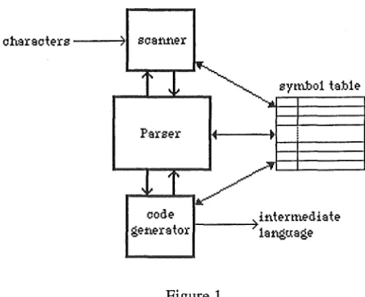
Conceptually a translator consists of four main program units (a) scal1ller (lexical analyser),
(b) parser (syntax analyser), (c) semantic analyser, (d) code generator.
i
f···
The scanner processes the input characters and recognises the symbols of the language. The parser takes these symbols and recognises the constituent parts of the program. With knowledge of these constituent parts the semantic analyser can gather information about what the program means. With this information the code generator can then generate equivalent code.
In recursive descent parsers, the actual structure of a translator. differs slightly this conceptual view. Central to it are compiling procedures that do the syntax analysis, which call the scanner, semantic analyser, and code generator. Often the semantic analysis is done along with the syntax analysis in the compiling procedures.
Symbolic information about symbols and variables are stored in a symbol table. All four program units of the translator need to access the table. The scanner inteirngates it to check if the string of characters read in correspond to a reserved word, or a user variable. The parser has to update information about variables as the are declared. The semantic analyser updates and uses inf01mation about variable types. The code generator stores and retrieves infommtion about memory addresses of variables.
The interaction between programs units and the symbol table is shown in figure 1.
code ge-:Mr:ator
synilio1
ta:ble-
ifite-rm.e-di:ate-1 - - - - +
1:aftgti:Sge-Figure 1.
4.2. Issues in Translator Implementation.
[image:16.600.138.404.314.530.2]4.2.1. The Symbol Table.
In the SDR-BASIC translator, the symbol table consists of an array of table elements. Each element consists of an identifier, a class identifier, and various other fields whose relevance depends on the class.
The classes of symbol table records and their relevant fields are:
Class Fields
Reserved words. The corresponding symbol. Built-in functions. The corresponding symbol.
The type the function returns.
Labels. A flag to indicate that the label has been referenced.
Variables.
Array variables.
A flag to indicate that the label exists.
The address of where the code for the line starts.
t
The address of where the users data starts after this line. The address in the code space of last used RESTOREstatement to this line.
t
The type.For string variables, the maximum size. The address of the variable.
t
The type.
For string variables, the maximum size. Number of dimensions.
Linked list of array dimensions. The address of the variable.
t
Note: The exact location of these might not be known at the time they are first referenced. In such cases, all references to them are chained together until the actual address is known. When it is, the chain is used to determine the addresses in the code space that need to be patched up. The last element in the chain has a value of -1.
A hash function is used to find particular elements in the symbol table. The key for the function is the identifier. The hash function used is:
index (ordinal value of first character* 17
+
ordinal value of last character* 103+
length of identifier* 55) modulo 503If the element at index is not the desked one, 37 is added to the index (modulo 503). The resolving continues until either the correct or an unused element is found. This hash function was chosen because it gives good results. Arriving at it was a bit of a hit and miss affak. The SDR-BASIC translator keeps a record of the number of retries that had to be made. By monitoring this, and changing the values of the factors, the hash function was able to be fine tuned.
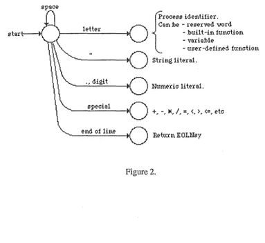
4.2.2.The Scanner
The scanner converts input characters to symbols. The following diagrams shows how the input symbol is determined from the first non-blank character.
t
rocess ideri.tifier. Si'L :be - reserved word- :bu:i.1 t -ifl. fuMtiofl. - vsris:b1e
- user -defiMd fuMtiofl.
---to
Shifl$j, 1i ters1 . 1eHer. , dig.it
Hum.eric 1i ters1.
specis1
o
- - - +, -, :IIE, /, =, <, >,<=,etc
[image:18.600.78.461.424.775.2]---11
e±\d of HMo
Return E OL:t-rsySeveral unusual features of the scanner need explaining.
In SDR-BASIC a variable is identified by its identifier and type. This means that all the following variables are all different.
banana% (integer)
banana$ (string)
banana! (real)
banana% () (integer array)
banana$ () (string array)
banana! () (real array)
To complicate matters, the following can appear:
banana (default type for identifiers starting with 'b')
banana () (array of default type for identifiers starting with 'b')
At some stage, the type of the identifier read in must be dete1mined. To simplify the parser, this is done in the scanner. As variables have unique entries in the symbol table, a unique identifier is created from the one read in. For example, if 'banana ' was read in, and the
'
default type for vaiiable begining with 'b' was string, then the unique identifier used is
'banana$'. Similarly, if the array 'banana' was read, 'banana$(' would be used.
Labels a.re handled in the scanner rather than in the parser. A label always appears at the start of the line. When the scanner finds a integer constant at the start of the line, it adds the label to the symbol table. Also, if there is are any previous references to this line eai·lier in the program, the scanner patches up the code space so that the branches are directed to the current value of the code pointer.
4.2.3. The Parser.
4.2.3.1. Recursive Descent Parsers.
Recursive descent compilers are designed for LL grammars. An LL grammar for SDR-BASIC is given in Appendix B.
The parser (for an LLl grammar) is constructed as follows. For each terminal symbol in the grammar, a procedure is written that checks to see if the last scanned symbol is correct, and then reads in the next symbol by calling the scanner. For each production, a procedure is written which calls the procedures corresponding to the symbols in the right hand side of the production in order. The parser is started by calling the scanner, and then calling the top-level parsing procedure.
This is a very basic recipe. It will normally be modified to avoid recursive calls. Also, terminal symbols that appear only in one production might be handled in the procedure for that production. For example, in the SDR-BASIC grammar, we have
<program> : := <lines>
<lines> : := <line> I <line> eoln <lines> For these productions the following Pascal procedures could be constructed.
procedure pPROGRAM; begin
pLINES; end;
procedure pLINES; begin
pLINE;
while (insy
=
eolnsy) do begininsymbol; {skip past end of line} pLINE;
4.2.3.2. Error Handling.
To detect errors a check is made to see if the symbol last read in from the scanner is the same as the one that is expected. If they are different, an error message should be displayed, and the symbol stream from the scanner should be resynchronised.
Resynchronisation requires knowing all the symbols that can follow the one that is being checked in the given context. To do this, a follow set is passed as a parameter to each of the parsers procedures. The follow set passed on consists of the follow set passed to the calling procedure plus the symbols that can follow in the given context. To resynchronise, input symbols are skipped until one if found to be in the follow set.
4.2.3,3. Type Checking.
Most of the type checking is concerned with expression parsing. The parser has to make sure that the types of operands being operated upon are the same. If they are not, either type coercion must be done or a type mismatch error must be given.
The way type checking for expressions is done is the same as if a parse tree were built up for the expression. At the leaves of this tree there are operands. At the nodes there are operators. When the scanner reads in an operand (variable, user defined function, literal, or built-in function) it can detennine its type. Starting at the nodes of the tree, the types can be propagated up until the type of the root node has known. The expected type of the expression can then be checked with the expected type of the top node for compatibility.
The propagation of types up the tree is done as follows. Each operator can only operate on a subset of types.
operator unary
-+
*
I
div
/\
<,:S:,>,~,:;t:
and, or, not
valid types integer, real
integer, real, string integer, real
integer, real real
integer real
Therefore, a check has to be made to see if an operator and its two operands are compatible. If they are not, an error has occured. If they are, then the two operands are corerced to the same type if need be, and the type is passed up the tree.
4.2.3.4. Automatic Type Conversion.
Coercion (automatic type conversion) occurs when the given and expected types in an expression are different, and it is possible to convert the given type to the expected one. In
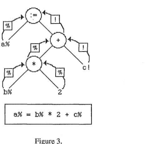
SOR-BASIC, this can happen between integers and reals. There are occasions when reals are coerced into integer as well as when integers are coerced into reals. If an operand is valid for both integers and reals, and coercion is needed, then the integer will be widened to form a real. An exception to the widening rule is with assignment, where coercion is always to the type of the left hand side variable.
Consider the following example.
[image:22.600.202.452.366.598.2]a%= b%
*
2 + c%Figure 3.
4.2.4. Code Generation.
Code is generated as the program is being parsed. Calls to the code generating procedures are made by the parser. There are procedures to do the following.
Add a instmction to the code space (procedure Genl) Add an integer (2 bytes) to the code space (procedure Gen2) Add a byte to the code space (procedure Gen3)
Add a real (6 bytes) to the code space (procedure Gen4) Add a string (1-256 bytes) to the code space (procedure Gen5) Create space for integer variables (procedure CreatelntegerSpace) Create space for string variabels (procedure CreateStringSpace) Create space for real variabels (procedure CreateRealSpace)
These routines maintain the code space and various pointers that reference it.
Each part of the parser handles the code generation for the part of the language that it parses. As an example, consider the SDR-BASIC GOTO statement. The syntax of the statement is:
GOTO label
The simplified code for this looks like:
(**)Genl (Branch); pLABEL ( ... );
{Generate Branch instruction} {Let pLABEL handle the rest!}
4.2.4.1. The Code Generated.
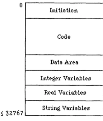
The code space generated by the translator looks like:
0
1:rdtistiot\
Code
Data Ares 11\teger Variables
Real Variables
[image:24.603.183.349.136.330.2]~ 32?67 Stri:t\g Variables
Figure 4.
The 1nitiation part of the code space con~ists of instructions to initialise the data pointer and variables to their default values.
The length of the code varies in length. It has all the code c01Tesponding to the SDR-BASIC program. The code area always ends in an Exit instruction.
The data area is variable length and always ends in two bytes of 255.
All va1iables of the same type are strored contiguously. This has been done for two reasons.
(a) To simplify the initialisation of variables.
(b) For future enhancements to the interpreter. At some later stage, variable space storage could be allocated in the interpreter. This would make the object code file much smaller. If
variable storage space was deallocated when a program terminates, memory would be saved in the SDR2. This is becaues only one program's vadables are active at on time.
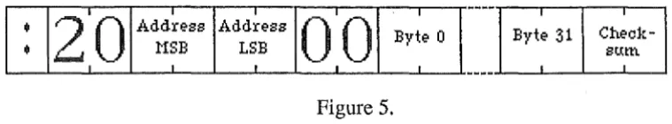
-4.3. Translator Output.
The translator must produce an object code file in the form of an SDR2 external program. The format consists of lines of the following ASCII characters.
2·0
I Io·o
I•
Address AddressByte O
•
HSB LSB Byte 31Check-I I sum
[image:25.598.76.456.161.231.2]I I I I I I I
Figure 5.
Bytes appear as the ASCII representation of their hexadecimal notation. For example, 32 is represented as the two characters '20'. The check sum is the negative of the sum of all the bytes on the line.
4.4. Issues in Porting the Macintosh Version to an IBM PC.
As the Macintosh version of the translator has been written in Turbo Pascal, it should be relatively stright forward to port it to an IBM PC environment.
Macintosh Turbo Pascal and IBM PC Turbo Pascal have the following differences:
(a). In both versions large programs must be broken up into segments. There are separate segments for code, data and heap space. The size of the segment depends on the computer system being used.
On the Macintosh, the segments are 32k long. There is a very simple compiler directive for doing this. One simply inc~udes a Pascal comment before a function or procedure in the form of
{S+ segment name}
All code generated after this point will be placed in the named segment.
On the IBM PC, the segments are 64k long. If more than one segment is needed, a complicated method of overlays is required.
The amount of 68000 code that is generated on the Macintosh is about 52k. This means that on the Macintosh segmentation has had to be done. However, assuming that about the same amount of 8086 code is generated on an IBM PC, there will be no need for segmentation.
i-(b) The Macintosh Version of Turbo Pascal has many enhancements over the PC version. For example, there are more powerful string to number conversions. Such functions have been avoided if they make for harder porting.
!
Section Five.
The Int'erpreter.
Translated programs will be loaded into the SDR2 where they will be run by an interpreter. The interpreter will be written in ADL and loaded as an external program.
Because of lack of time, this part of the project has not been completed. This section gives an outline to what the interpreter should do. Possible difficulties with implementation are high lighted.
(a) Determining which program to interpret.
The interpreter needs to know which program to interpret. As there can be many in the SDR2's memory at any one time, some sort of menu selection is needed. Once the program has been selected interpretation can start.
(b) Machine variables.
Effectively, the interpreter emulates a virtual machine, whose machine language is the same as the intermediate language used for this project. The interpreter will therefore need to have some variables and data structures in order to manage the code and data.
i. Program Counter.
The program counter holds the address of the next instruction to be interpreted. Before a program is interpreted, the program counter is initialised to zero.
ii. Program Stack.
The intermediate language that is used is a stack oriented one. Therefore a stack must be implemented. It is possible that the ADL stack can be used for this purpose. The stack will
be empty when the program starts and when it finishes. The stack elements are 16 bit signed integers.
iii. Stack Pointer.
If a stack is implemented, a ~tack pointer is needed to point to the first empty element in the stack.
iv. Frame Pointer.
A frame pointer is needed to reference parameters to user defined functions and built-in functions in the stack. 1
v. Data Pointer.
The data pointer is needed to reference the data area, where the values in the SDR-BASIC DATA statement are stored. The data pointer is reset by the Restore address
instruction.
vi. Real and String Operand Space.
As stack elements are 16 bit values, real and string operands cannot be stored there. Some area is needed internally in the interpreter for this purpose. A problem arises here because there is no limit to the number of real or stting operands that need to be stored. For example,
a!
=
bl! A b2! A b3! A b4! A • • • bnlrequires space for n reals.
( c) Interpreting Instructions.
The interpreter proceeds by starting at the first instruction in the code. It must then interpret it. This requires reading relevant operands from the code, and stack, and updating the stack, program variables and 'machine' variables. After the instruction has been interpreted, the interpreter should procede to the next.
As the intermediate code will reside in the SDR2 memory at an address not known at translation time, all addresses in the code are in effect an offset from the start address of the code. Therefore, address c01iversion will need to be made at run-time.
Interpretation stops when an error or an Exit instmction is reached.
(d) Problem Instructions.
Most of the intermediate language instructions are straight forward. However, some are quite complicated.
i. Nextlnteger, NextReal.
These are high level instmctions for controlling the FOR looping construct in BASIC. The format of these is:
Nextlnteger start of loop address NextReal start of loop address
On the stack both expect the following:
Address of loop variable (Next to top) Address of control block (Top of Stack)
The control block consists of the following:
Upper bound .of loop· Loop increment value
The type of these and the loop variable are the same. The processing that has to be done is:
1) Load the value of the loop variable onto the stack. 2) Load the loop increment value.
3) Add these values together to give the next value of the loop variable. 4) Store the new value of the loop variable.
4) If the sign of the increment value is positive then:
4a) if the upper bound is greater than the new loop variable value, branch to start of loop, else terminate loop, else:
4b) if the upper bound is less than the new loop variable value, branch to start of loop, else terminate loop.
ii.Readinteger, ReadReal, ReadString
Only strings are stored in the data area. Therefore, to read an integer or a real, the string will need to be converted.
iii. CallFunc, ReturnFunc
When a user-defined function is called a stack frame must be built up. In this frame, the previous value of the frame pointer and the return address must be stored. After a function with n parameters has been called, the stack looks like:
stack pointer-.
return address
frame pointer-.
Previous FP
(FP)
,_p_a_r-am_e_te_r_n--1
parameter 1
The user-defined function will cause the resulting value to be left on the stack. On return from a function, this stack frame must be broken down. The program counter will need to be set to the return address, the frame pointer reset. The parameters on the stack should be removed. The resulting stack will have the result of the function at the top.
iv. Heap Access.
The approach for heap access was designed to be easy for the programmer to use and for the writer of the translator to write. Unfortunately, the interpretation will be very difficult.
1. Fields
SDR-BASIC has a set of predefined variables that correspond to the names of the fields in heap records. The variables are stored in the interpreters address space rather than in the translated program's variable storage area. The reason for this is that there are many of them, and having to include them in all programs would require a lot of memory.
2. Adding records to the heap.
When a record is added to the heap, the interpreter has to detem1ine the type of the record. This is done by looking in the appropriate record. It must then transfer the variables corresponding to fields in the records of this type to the heap. To do this efficiently, a look-up table is required.
3. Retreiving records from the heap.
Section
Six.
Results.
6.1. What has been done.
Up until mid term 1987, much time was spend researching relevant topics. A survey of the SDR2 was undertaken. What was found is given in Appendix A.
Many versions of BASIC were examined for suitable features. Of these Microsoft BASIC was chosen as the one to base SDR-BASIC (see Appendix B) upon.
From personal experience and from relevant literature, the intermediate language was designed. An overview is given in Appendix C.
Programming was started in mid tem11987. It was originally intended for the development work be done on an IBM PC, lent by Datacom. Because of high demand for IBM PCs at Datacom, this was not possible.
The translator was wdtten using Turbo Pascal on an Apple Macintosh. Over 3500 lines of code have been produced. The translator has been completed to the stage where it correctly parses, type checks and generates code. If there al'e no errors, the code generated is output in the SDR2 external file format. An error listing is produced. Also, a dump of the code in intermediate language format is produced. Some documentation for the translator is given in Appendix. D.
There are still one or two loose ends to tidy up with the translator. The author did not have time to determine the format of real numbers as they are stored internally in the SDR2. Where reals must be put in the code (in the LoadConstinteger instruction) an appropriate sized space is allocated.
The translator has not yet been ported to an IBM PC. However, there should be little difficulty in doing this.
Because of lack of time, the implementation of the interpreter was not attempted. Much back ground work would need to be done before any programming could start. ADL has to be mastered, along with understanding the many details of the internal structures of the SDR2.
6.2. What More Could Be Done.
There is still a lot of work that could be done in this project. It there was time the following would have been attempted.
6.2.1. Enhancing SDR-BASIC.
6.2.1.1. Adding more BASIC features.
SDR-BASIC is based on Microsoft BASIC. There are many features that have not been implemented so fa1· because they were considered to be not important. Many of these are string functions, like STRING$(string, n) which returns a string constisting of the given string duplicated n times. There are also numerical functions like a random number generator. These would not be useful for most surveying applications. However, they would be if the programmer would like to develop recreational programs.
An important omission is that there is no way of reading one input character at a time from the keyboard. SDR-BASIC INPUT reads in a whole line of characters that end in a new-line. Often there are times when it would be convenient to scan the keyboard to see whick keys are being depressed or to wait until one key is pressed. Many BASICs provide an INKEY$ or GET function to do precisely this. These could be adopted by SDR-BASIC.
Experienced SDR-BASIC programmers might like there to be structured programming constructs. BASIC programs tend to turn quickly into a rats nest of branches. Structured programming constructs like procedures, functions, and local variables could make SDR-BASIC programms much more readable.
6.2.1.2. Providing better interfacing with the SDR2.
With SDR-BASIC a programmer can access heap records and write their own input/output drivers. There are many other features of the SDR2 that would be useful.
(a) Access to the configuaration variables.
Configuration variables specify the working environment of the SDR2. They can be viewed using the Parameters menu option. The variables include:
Unit used for input and output. (Values stored in the heap are in standard units). - Angle (degrees)
- Distance (meters) - Pressure (mm Hg)
- Temperature (degrees Celsius) Optional correction flags
- sea level correction - Atmosphere correction Tolerances
- Vertical observation tolerance
- Horizontal observation tolerance j
Input/Output parameters - Tranfer speed - Parity option flag - Word length
- Checksum option flag -Acoustic
- Timeout period
These parameters are stored in the heap, and so they can be retreived with the heap manipulation commands. However, it would be much nicer if there were a set of pre-defined variables for these. These variables would need to have values assigned to
them just before a program is run.
with. With the present version of SDR-BASIC, the programmer must write user defined functions to convert between units. For example, to convert between degress Celcius and Fahrenheit,
DEF FNCtoF (degC) = degC*9/5 + 32
Functions to convert between these units and other commonly used ones will make customising input and output much easier.
(c) Angle input.
On the SDR2 angles can be entered in as decimal values or in a special degrees/minutes and seconds format (ddd.mmss). However, SDR-BASIC only has routines to input integers, reals and string. It is not a trivial task to provide angle input using the present features of SDR-BASIC. Therefore, introducing an angle input command would be extremely useful. (d) Input/Output modifications.
In SDR-BASIC there is no way of telling if output or input was successfully completed. Knowing the status of i/o operations makes for more robust programs. A pre-defined variable could be introduced called STATUS. It could be updated after every input and output to reflect how successful the operation was.
In SDR-BASIC the input routines read in information until a new-line is reached. Often, the delimiter might be something different, such as a space or comma. Some way of specifying the delimiter would make input more flexible.
6.2.2. Improving the Translator.
The translator reads in a SOR-BASIC program and produces equivalent inte1mediate code. There are many ways in which this code can be improved.
(a) Adding range checking information.
The intermediate language has instructions designed for range checking. (see Appendix C).
To keep the amout of code to a minimum, the translator does not make use of them. However, as inexpe1ienced programmers will be using the translator, it might be desirable to add range checking.
(b) Compiler directives
Once a program has been written, tested and found to be without errors, the code size could be reduced by turning range checking off. To do this compiler directives could be introduced. These could f01m a part of an SDR-BASIC comment. For example
REM *norange would tum range checking off, and
REM *range
would tum range checking on again.
Many other compiler directives could be included. Ones to control listings, code generation and case sensitivity are obvious candidates.
(c) Adding debugging information.
(d) Warnings against bad programming practices.
BASICs tend to be very liberal when it comes to branching. It is possible to branch into a loop. Such practices often lead to stange errors occuring. To deter the programmer from doing this, warnings could be given at translation time.
( e) Optimisation.
As memory and speed requirements of the intermediate code are very important for this project, an attempt at optimisation would be worth while.
(f) The intermediate language could be improved.
Some attention to compactness was made when the intermediate language was designed. The end result was quite adaquate. However, more time could be spent fine-tuning. The result would be far more compact code.
All operands are 16 bit signed integers. Often only 8 bit integers are needed. Therefore, variable length operands could be used. For example, the instruction LoadConstinteger has one operand which is always in the range -32768::;; operand::;; 32767. If the operand was in the range O ::;; operand ::;; 255 only 8 bits are needed.
6.2.3. Improving the Interpreter.
The specifications for the interpreter in section 5 are for the translated code as it now stands. If changes were made elsewhere they would have to reflected in the interpreter also. There are also a few ways to improve the interactivity of the interpreter.
(a) Allocation of Variable Storage Space.
At present variable storage space is included as a part of every translated program. However, the variables only remain active during program execution. Before and after a program is run they are not used. To save on space, the code and interpreter could be modified so that the variables were allocated when a program starts running, and are deallocated when the program ends. In this way, at most one set of program variables occupy memory at one time.
(b) Debuging Facilities.
The suggestion of adding debugging information to the code was mentioned in 6.2.2. part c. The interpreter would be able to make use of this information, especially when run-time errors occur. Also, a trace facility could be introduced. The interpreter could process one line, display the line number and then wait for a key press. This would allow non-fatal errors to be pin-pointed more accurately. '
(c) Loading in SDR-BASIC Programs.
6.2.4. Improving the Development Environment.
At the moment, programs will be written and translated on an IBM PC, and the intermediate code will then be loaded into the SDR2. Testing of the program will be done on the SDR2. If any modification is needed, the source on the IBM PC must be updated, retranslated, down loaded to the SDR2, and retested. Ideally, the turn around time between testing and modification should be kept to a minimum. The following will make for a better development environment.
(a) IBM PC testing phase.
An IBM PC-based interpreter could be implemented so that the whole testing phase could be done in the same environment. To do this, ADL and the SDR2 software would need to
be ported to an IBM PC. This is a major task in itself.
An alternative is to write an interpreter in Pascal which would test the standard features of SDR-BASIC. Though not totally useful, it would give some assurance to how error-free a program is.
Section Seven.
Conclusion.
Implementing a BASIC translator for the SDR2 is a worthwhile endeavor both from a practical and theoretical point of view. There is a need for this software product in the surveying world. At present, users of the SDR2 electronic field book have to use a powetful yet inflexible computer. There are many opportunities that will open up when the surveyor can develop and use his or her own software.
Much has been learnt about the practical aspects of translator design. From designing the BASIC language, through to designing the intermediate code and the translator, many compromises have had to be made to take into account the environment that the final product will be used.
The end result of this project is that a translator for SDR-BASIC has been written. As the intermediate code interpreter has not yet been implemented, the code produced could not be tested. However, the author is confident that the code produced is satisfactory, because the code that is produced look sensible on close analysis.
Sectio11 Eight.
References.
[l] SDR2 Electronic Field Book, Application Guide
[2] S. Pemberton and M.C. Daniels, Pascal Implementation, Compiler and
Assembler/Interpreter, Ellis Horwood 1982
[3] S. Pemberton and M.C. Daniels, Pascal Implementation, The P4 Compiler, Ellis Horwood 1982
[4] MBASIC-86 Reference Manual, Microsoft Corporation, 1982
Appendix A.
The SDR2
Datacom Software Research has developed software for a hand-held data recorder used by surveyors, called the SDR2 Electronic Field Book. The SDR2 collects and stores observations from survey instruments. A complete range of field data collection programs and calculation programs are provided so that observations can be checked and ve1ified in the field. Observations are taken automatically from electronic survey instruments and can be entered via the keyboard for optical instruments. The stored data in the SDR2 can be transmitted to a variety of different types of data processors in a variety of ways.
A.1. The Hardware
The SDR2 hardware is based on the MSI/85 portable tenninal. The MSI/85 is 9cm x 15cm x 4cm and weighs about 0.5kg. It can be held in one hand, as therefore is truely portable. Enhancements to the basic MSI model have been made. These include a keypad especially designed for the SDR2, and onboard EPROM containing the SDR2 software.
The SDR2 is based on an 8-bit microprocessor. The address bus is 16 bits wide, giving 64k of addressable memory. This is divided into 32k of ROM, and 32k of RAM. More recent versions of the SDR2 have up to 128k of RAM, which is achieved through page switching. The contents of memory is retained permenantly, even when the SDR2 is not in use.
The SDR2 has a 16 character liquid crystal display.
The keypad consists of 33 rubber keys. Included in these are numbers O through 9, decimal point, minus, arrow keys (for moving around through menu options and data records), on and off keys, shift, clear, enter, and 10 keys for accessing the various menus and programs. Alphabetic characters can be entered from the same keypad by using a shift key to toggle between numeric and alphabetic modes.
To be able to connect directly to electronic survey equipment the SDR2 has an in-built (15 pin, non-standard) interface, and comes with the appropriate cable. The cable has a special 6 pin connector to interface with survey equipment. The same connector can can be connected to a printer adaptor. This allows hard copies of the collected data to be made. With an optional communications adaptor (RS232) the SDR2 can be connected to a computer port using the same cable.
On top of these there is a built-in modulator or acoustic coupler. This can be used do download collected data via a telephone line to a remote computer. The acoustic coupler is also used to provide audio feedback on key depression.
A.2. The Software.
The software that comes with the SDR2 consists of data collection programs, calculation programs, searching programs that retrieve particular records from the data collected so far, and input/output programs.
The calculation programs perform typical surveying calculations. They are:
Traverse: Provides the field data collection procedures necessary for a transverse including side shots, coordinates and closure calculations.
Inverse: Computes distances and angles between two known points.
Topography: Automatic recording of observations, reduced data or coordinates for topographical surveys.
Resection: Determines the coordinates of the instrument station from sets of observations to known points.
Remote elevation: Calculation of the relative height of an object directly above or below a sighted target.
Collimation: Determination of the instrument's collimation error for automatic correction of observations.
Slope reduction: Calculation of the vertical and horizontal components of an observation. Coordinates: Calculation of the coordinates of a point.
Setting out: Location of points in the field using known coordinates. Keyboard input: Input of known coordinates or directions.
The software in the SDR2 resides in the 32k of EPROM. It has been wdtten in a combination of ADL and assembler.
ADL is very similar to Forth. ADL is stack based and the language syntax is in postfix notation. It is a 'threaded' language. There are a few primitives that are written in assembler. Higher level commands are defined in terms of these and other ADL commands. Input and output routines have been written in assembler to achieve a high level of performance.
ADL is implemented using tables. Every ADL instruction is represented by a one byte or two byte number. When an ADL program is interpreted, the bytes are used as indexes into these tables. The table contains the address of where the code for each instruction starts. This table driven approach causes ADL to be ve1y compact, even more so than assembler.
A.3. Data Strorage.
Data that has been collected is stored as records in a heap. The heap is partitioned sections. Each section consists of a collection of records pertaining to on particular surveying job or site. Each job is logically independent from all others. If more data is collect, or previous data is reviewed it id done so within the current job.
The records in the heap are variable length. Every record has many fields. The first two are always the same. They are:
Type Code
Derivation Code
The type code defines the type of the record. The derivation code specifies where the particular record was created.
The elements in the fields have varying types. For example, an observation record has:
Type code 09 (integer) Derivation Code (2 characters) Source point number · (integer) Target point number (integer) Slope distance (real) Vertical angle (real) Horizontal angle (real)
Description (16 characters)
A complete listing of the fields in each record types is given in the SDR2 Application Guide [l] on page 121.
All measurement values in the heap are stored in standard units. They are: Measurement Unit
Length Angle
Metres Degrees
Pressure mm of mercury Temperature Degress Celcius.
A.4. External Programs.
The SDR2's RAM is also used to store programs that have been loaded in. These programs are normally written in ADL. There are size restriction on external programs. Also, due to the table-chiven nature of ADL there is a limitation on the total number of variables and functions used in the external program.
A.5. System Parameters.
The SDR2 has a set of parameters and configuration variables that give much flexibility to the system. They are explained in detail in the SDR2 Application Guide. [l].
(a) Instrument Parameters.
These parameters are needed to define the electronic surveying equipment being used. Included here are:
INSTRUMENT type SERIAL NO of instrument
VERTICAL ANGLE, where the vertical angle is measured from.
(b) Measurement Units.
The unit types for measurements can be chosen from a set of options. For example DISTANCE UNIT: metres or feet
( c) Corrections.
PRESSURE UNIT: MmHg, Inch Hg or mbar TEMPERATURE UNIT: Celcius or fahrenheit
Allowances can be made for several corrections if desired. These correction include SEA LEVEL CORRECTION
PRESSURE & TEMPERATURE CORRECTION
(d) Tolerances.
(e) Input and Output Parameters.
The linespeed, format and mode of data transmission can be selected.
TRANSMISSION SPEED
PARITY SETTING
WORD LENGTH
CHECKSUM generation option
Appendix
B.
SDR-BASIC.
SDR-BASIC is based on Microsoft BASIC [4]. Because of this, this section will only high light the areas where SDR-BASIC deviates radically from the Microsoft version.
B.1. A Brief Overview of SDR-BASIC. (a) Line Format.
Program lines in SDR-BASIC have the following format (curly brackets idicate optionals):
{label} statement {: statement ... } <carriage return>
The programmer has the option of placing more than one statement on a line, but each statement must be separated from the last by a colon.
Labels are optional in SDR-BASIC. When they are used, they can appear only once, in any order. Labels must be an integer value in the range of O to 327 67.
(b) Standard Features That Have Been Implemented. Briefly, the following are supported:
Variable identifiers: a letter followed by up to 15 p.lphanumeric characters. Types:
Default types:
Assignment:
integers, reals, and strings, plus multidimensional arrays in each of these types.
All variables are assumed to be reals, unless:
a) Followed by a"!" (real),"%" (integer) or"$" (string),
b) Default type changed with DEFINT (integer), DEFSTR (string), or DEFSNG (single precision real). There are no allowances for
double precision reals.
LET is optional. CLEAR sets all numeric values to 0, and strings to null("").
Built-in Functions: truncate (INT), absolute value (ABS), sine (SIN),
integer to character conversion (CHR$), string length (LEN),
string to numeric conversion (VAL), numeric to string conversion (STR$).
User-Defined Functions: The user can specify his or her own function, being any type and having any number of parameters of any type.
e.g. DEF FNarcsin (x)
=
ATN (xI
SQR(-x *x+l)) Control Suuctures: branch to a label (GOTO),Input/Output:
Other:
conditional statements (IF .. THEN .. ELSE), for-loops (FOR.NEXT),
subroutine calls (GOSUB .. RETURN), while loops (WHILE .. WEND),
repeat loops (REPEAT .. UNTIL),
computed goto and gosub (ON .. GOTO . ./ON .. GOSUB .. ), program termination (END).
write to display (PRINT), input from keyboard (INPUT), user data (DATA),
read user data (READ),
reset data pointer (RESTORE).
Comments (REM). The rest of the line is ignored.
(c) Deviations from Standard BASICs.
1. The DIM statement.
The size of a dimension must be expressed as an integer constant.
2. The INPUT Statement.
Only one variable can be input at one time,
3. The FOR.NEXT loop.
In most BASICs, ajoining NEXT statements can be elided. Consider, FOR i% 1 TO 10
FOR j% = 1 TO 10 NEXT j%