Security Analysis of Mobile
Payment Systems
Atul Kumar
EIT ICT Labs Master School
University of Twente
Under Supervision of:
Prof. Dr. F.E. Kargl
The Services, Cybersecurity and Safety Research Group
University of Twente, The Netherlands
Jordi van den Breekel
Eleonora Petridou
Information Protection Services
KPMG Netherlands
A thesis submitted for the degree of
Master of Science in Security and Privacy
Acknowledgements
First and foremost I offer my sincerest gratitude to my supervisor, Prof. Dr. F.E. Kargl, who introduced me to the world of Near Field Communication (NFC) during one of the lectures on the Security and Privacy of Mobile Systems course, which was part of my Master study program at the University of Twente, The Netherlands. His support and immense knowledge greatly helped me to develop the different concepts discussed in this thesis. His constructive feedback was very helpful in identifying areas of improvement. One simply could not wish for a better or friendlier supervisor.
Next, I am very thankful to Jordi van den Breekel, my supervisor at KPMG. He has supported me throughout my thesis with his patience and knowledge whilst allowing me room to work in my own way. I at-tribute the level of my Masters thesis to his encouragement and effort and without him this thesis would not have been completed or writ-ten. He always motivated me to perform structured research which was very crucial in achieving the results in a timely manner. He was one of my biggest sources of motivation and inspiration.
I would also like to thank Eleonora Petridou, my second supervisor at KPMG. She always encouraged and helped me in improving the quality of my thesis. I would also like to thank her for introducing me to KPMG during one of the guest lectures at the University of Twente.
division at KPMG was one of the best experiences of my life. In my daily work I have been blessed with a friendly and cheerful group of fellow colleagues.
Nils Rodday, my friend as well as my classmate, has been an invalu-able help through out my thesis. He was always availinvalu-able to have discussions and provide his useful opinions and was always willing to help me.
I am also indebted to the many countless contributors to the “Open Source” programming community for providing the numerous tools and systems I have used to produce both my results and this thesis. The entirety of my thesis has been completed using such technologies.
I am also thankful to Dr. Andreas Peter, a member of the graduation committee, for all his help and support in offering internships with different companies and various topics to choose from.
I also place on record my sense of gratitude to everyone who directly or indirectly lent their support in this thesis.
Abstract
Contents
Contents v
List of Figures ix
Acronyms . . . xii
1 Introduction 1 1.1 Mobile Payments . . . 1
1.2 Security Requirements . . . 2
1.3 Motivation of the Thesis . . . 2
1.4 Research Questions . . . 5
1.5 Methodology . . . 5
1.6 Scope . . . 6
1.7 Organization of the Thesis . . . 6
2 Background 8 2.1 Standard mobile payment system model . . . 9
2.2 Security Mechanisms . . . 10
2.2.1 Device and owner identification . . . 11
2.2.2 Tokenization . . . 11
2.2.3 Trusted Execution Environment . . . 18
2.2.4 Secure Element . . . 20
2.2.5 Cloud based approach . . . 22
2.2.6 Code Obfuscation . . . 23
2.2.7 White-box Cryptography . . . 24
CONTENTS
2.3.1 Modes of communication . . . 25
2.4 NFC layers and standards . . . 25
2.5 Card Emulation . . . 28
2.5.1 Host-based Card Emulation . . . 29
2.5.2 Different flavors of HCE-based Mobile Payment System . . 30
3 Secure Element and its different flavors 32 3.1 Secure Element . . . 32
3.1.1 UICC . . . 33
3.1.1.1 Trusted Security Manager . . . 34
3.1.1.2 Over-the-Air provisioning . . . 35
3.1.1.3 Security features and available interface . . . 35
3.1.2 Embedded Secure Element . . . 37
3.1.3 Micro Secure Digital (Micro-SD)-based SE . . . 38
3.2 SE in the Cloud . . . 39
3.3 Comparison of the different forms of SE . . . 41
4 Host-based Card Emulation 44 4.1 Host Card Emulation . . . 45
4.2 Security Mechanisms . . . 45
4.3 Relay Attack . . . 46
4.3.1 Relay Attack on HCE-based Mobile Payment System . . . 48
4.3.1.1 Hardware-based Relay Attack . . . 48
4.3.1.2 Attack Scenario . . . 49
4.3.1.3 Software-based Relay Attack . . . 51
4.3.1.4 Attack Scenario . . . 51
4.4 Man-in-the-Middle Attack . . . 53
4.5 Denial-of-Service Attack . . . 55
4.5.1 Corrupt Routing Table . . . 56
4.5.2 Application Identifier (AID) conflict . . . 56
4.5.3 Quick Battery Discharge . . . 58
4.5.4 Malicious POS terminals . . . 58
CONTENTS
5 NFC SIM Card 62
5.1 Vodafone NFC SIM card . . . 63
5.1.1 Vodafone Wallet . . . 63
5.1.2 Vodafone SmartPass . . . 63
5.2 Spoofing Attack . . . 64
5.2.1 Attack Scenario . . . 65
5.2.2 Assumptions . . . 65
5.2.3 Goal of this attack . . . 67
5.2.4 Limitation . . . 67
5.3 Relay Attack . . . 67
5.3.1 Attack Scenario . . . 67
5.3.2 Assumptions . . . 68
5.3.3 Goal of this attack . . . 69
5.3.4 Limitation . . . 69
6 Countermeasures for Relay attack 70 6.1 Challenge Response Protocol . . . 70
6.1.1 Replay Attack . . . 71
6.1.2 Challenge response protocol for protection against relay at-tack . . . 72
6.2 Manual challenge response protocol . . . 72
6.3 Side channel challenge response protocol . . . 74
7 Proof of Concept 77 7.1 Relay Attack on HCE . . . 77
7.2 The Experiment . . . 78
7.2.1 First Phase . . . 79
7.2.1.1 Arduino Uno Board . . . 80
7.2.1.2 Seeed Studio NFC Shield v2.0 . . . 80
7.2.1.3 Samsung Galaxy S4 . . . 80
7.2.1.4 Arduino IDE . . . 80
7.2.1.5 A Laptop . . . 81
CONTENTS
7.2.1.7 Seeed Studio PN532 library implementing HCE . 82
7.2.2 The Experiment Setup . . . 82
7.2.2.1 Result . . . 84
7.2.2.2 Experiment with Android 4.4.2 on Nexus 7 . . . 86
7.2.2.3 Experiment with Android 5.1.1 on Nexus 5 . . . 87
7.2.3 Second Phase . . . 88
7.2.4 The Experiment Setup . . . 88
7.2.4.1 Result . . . 89
7.2.5 Countermeasures . . . 92
7.2.6 Experiments for verifying device lock feature . . . 93
7.2.6.1 The Experiment Setup . . . 93
7.2.6.2 The Experiment . . . 93
7.2.6.3 Results . . . 96
8 Future Work and Conclusions 98 8.1 Overview . . . 98
8.2 Conclusion . . . 100
8.3 Future Work . . . 102
8.3.1 Test the new attack vectors proposed . . . 102
8.3.2 Attacks on NFC Subscriber Identity Module (SIM) card . 102 8.3.3 Other possibilities of hardware-based relay attacks . . . 103
8.3.4 Countermeasures to relay attacks . . . 103
Appendix A 104
Appendix B 108
List of Figures
2.1 An overview of Chapter 2 . . . 8
2.2 The transaction flow and key parties in mobile payment model. Adapted from [15] . . . 10
2.3 Account Data [20] . . . 12
2.4 The flow and key elements in token-based payment mechanism [9] 17 2.5 Typical Track2 Data vs LoopPay Tokenized Track 2 data [33] . . 18
2.6 Generate TPV [33] . . . 19
2.7 Sample token format as defined by PCI DSS [32] . . . 19
2.8 The normal and secure world environment [7] . . . 20
2.9 TEE Architecture defined by GlobalPlatform [12] . . . 21
2.10 Software based relay attack [6] . . . 22
2.11 Comparison between NFC layer and OSI layer [16] . . . 27
2.12 ISO standards for contact and contactless cards [14] . . . 28
2.13 Android HCE protocol stack [1] . . . 28
2.14 Android operating with both SE and HCE Adapted from [1] . . . 30
3.1 An overview of Chapter 3 . . . 33
3.2 Key capabilities of TSM [21] . . . 34
3.3 UICC-based SE [26] . . . 36
3.4 ISD and SSD hierarchy as suggested by Global Platform [5] . . . . 37
3.5 Embedded SE [26] . . . 38
3.6 MicroSD based SE [26] . . . 39
3.7 Comparison of different forms of SE [3] . . . 43
LIST OF FIGURES
4.2 Standard architecture of relay attack [28] . . . 47
4.3 Wireless Charger . . . 49
4.4 Wireless Charger as a mole for relay attack . . . 50
4.5 Software-based relay attack . . . 52
4.6 Man-in-the-middle attack . . . 54
4.7 Malicious POS terminal causing DoS attack . . . 59
5.1 An overview of Chapter 5 . . . 62
5.2 Spoofing attack Scenario for NFC SIM card . . . 66
5.3 Wireless charger as a mole . . . 68
6.1 An overview of Chapter 6 . . . 71
6.2 Manual Challenge Response protocol . . . 74
6.3 Side Channel Challenge Response protocol . . . 75
7.1 An overview of Chapter 7 . . . 78
7.2 Samsung Galaxy S4 with Android 4.4.2 . . . 81
7.3 Initial Setup . . . 83
7.4 Arduino IDE . . . 83
7.5 The overall setup . . . 84
7.6 Serial monitor output . . . 85
7.7 Serial monitor output showing communication with android HCE app . . . 85
7.8 Source code of the sample HCE app. Refer Appendix A . . . 86
7.9 Experiment with Android 5.1.1 . . . 87
7.10 Google Nexus 5 with Android 5.1.1 . . . 89
7.11 Initial setup with Google Nexus 5 and Wireless Charger . . . 90
7.12 Google Nexus 5 is kept on the Wireless Charger along with the NFC antenna . . . 91
7.13 Google Nexus 5 kept on the Wireless Charger(powered OFF) along with NFC antenna . . . 92
LIST OF FIGURES
7.15 Google Wallet communicates with the NFC reader when the device is locked . . . 94 7.16 Use of apktool and SignApk . . . 95 7.17 Sample HCE application with requireDeviceUnlock set to true and
Nexus 7 screen is on and locked . . . 95 7.18 requireDeviceUnlock attribute is set to false in the sample HCE
application and true in Google Wallet . . . 96 7.19 Serial monitor shows that NFC reader is able to communicate to
Acronyms
Acronyms
AID Application Identifier
APDU Application Protocol Data Unit API Application Programming Interface CPU Central Processing Unit
CSC Card Security Code
EMV Europay, MasterCard, and Visa eSE Embedded Secure Element
GSM Global System for Mobile Communications HCE Host Card Emulation
ID&V Identification and Verification IIN Issuer Identification Number IPC Inter Process Communication ISD Issuer Security Domain
ISO International Organization for Standardization Micro-SD Micro Secure Digital
Acronyms
MST Magnetic Secure Technology NFC Near Field Communication
NFC-WI Near Field Communication Wired Interface OSI Open Systems Interconnection
OTA Over-the-air
PAN Primary Account Number
PCI DSS Payment Card Industry Data Security Standard PIN Personal Identification Number
POS Point of Sale QR Quick Response RF Radio Frequency
RFID Radio-frequency Identification SE Secure Element
SIM Subscriber Identity Module SMSC Short Message Service Centre SSD Supplementary Security Domain
SSL/TLS Secure Socket Layer/Transport Layer Security SWP Single Wire Protocol
Acronyms
TPV Token Part Value
TSM Trusted Services Manager
UICC Universal Integrated Circuit Card
Chapter 1
Introduction
This chapter provides an introduction to the mobile payment system and its se-curity requirements. It discusses the motivation behind this thesis. It provides the research questions which this thesis will try to solve. It discusses the method-ologies which will be used to provide solutions to the research questions. It also defines the scope and the overall organization of the thesis.
1.1
Mobile Payments
additional features by including multiple types of sensors and hardware compo-nents, which led to the creation of a wide number of application areas. One of them was a mobile-based payment system whose usage has doubled between 2012 and 2013 to $1 billion, and which is predicted to reach $57 billion by 2017[22]. Some of the key requirements for such a system are usability and security. As cards are being replaced by mobile phones, it will become more comfortable for the user since there is no need to carry credit or debit cards in their wallet. However, comfort should not lead to the compromise of security. It is necessary to implement security mechanisms to protect confidential data, i.e. card holder data. The security mechanisms should cover the confidentiality, integrity as well as availability of confidential data.
1.2
Security Requirements
Security is one of the key requirements for mobile-based payment systems. It needs to assure confidentiality and integrity of data involved in the transaction. It also requires proper authentication mechanisms so that each party involved in the transaction can be assured that they are talking to the right entity. The last requirement is non-repudiation which ensures that there is adequate proof of the message being sent by the intended party such as payment application or service provider. Some of these requirements are fulfilled by using cryptographic mechanisms like encryption, digital signatures, Personal Identification Number (PIN) codes, One time passwords or bio-metrics.
1.3
Motivation of the Thesis
The current mobile payment environment is drastically changing with the intro-duction of technologies like Near Field Communication (NFC), Secure Element (SE), Host Card Emulation (HCE), Quick Response (QR) Code and Magnetic Secure Technology (MST)1. Out of these, NFC, SE and HCE have received wider
acceptance. Most of the mobile payment applications currently available utilizes
NFC. Therefore, this thesis will focus only on NFC-based mobile payment.
In the case of hardware-based SE1, the deployment and management of mo-bile payment solutions is dependent on the SE manufactures. Access to the SE is managed by SE manufacturers. Therefore, the service providers like financial in-stitutions have to rely on the SE manufacturers. For example, if a service provider uses Universal Integrated Circuit Card (UICC)-based SE to deploy the payment application, the access is managed by Mobile Network Operators (MNOs) which adds additional cost for the service provider and also restricts the usage of the application to the users who have the UICC from the same MNOs. With the introduction of HCE in Android KitKat 4.4, it is possible to emulate a payment card without any need for hardware-based SE. This change has allowed banks and service providers to develop mobile payment solutions which do not have any dependency on hardware-based SE. Many mobile devices with NFC capabilities and running Android 4.4 or above can emulate a payment card. However, re-moving hardware-based SE will impact the security of these solutions as there will be a lack of local secure storage which might be needed by mobile payment solutions. Therefore, an analysis is required as to whether introduction of HCE actually lowers the security level (and how much) compared to SE without taking into account the requirement to enhance security.
A relay attack is considered as one of the prevalent attack vectors because of its simplicity, its effects and its ability to circumvent the cryptographic protec-tions. The countermeasures such as time or distance-bounding protocols which are suggested or implemented for relay attack have some limitations. This can be illustrated by an example. So-called relay attacks forward all requests from a Point of Sale (POS) terminal to a (typically infected) legitimate smartphone where data is stored in the SE. One of the proposed countermeasures for mit-igation is time-bounding protocol. The time bounding protocol measures the round-trip-time between Point of Sale (POS) terminal and the smartcard; if this time is too long, an alarm would be triggered and the transaction is refused. However, it is challenging to fix the maximum round-trip time required, which
limits the overall efficiency of this protocol. When introducing HCE, data may be stored in a cloud-based SE somewhere in the Internet. Communication with this cloud-based SE obviously introduces unpredictable additional delay and may render the time-bounding protocol ineffective. One of the security mechanisms implemented in HCE is to disable the NFC which in-turn stops the HCE service, if the device screen is inactive. Does this protect the mobile device from inter-acting with an unintended device to hinder a relay attack? It is these kinds of consequences of HCE introduction that this thesis investigates. Our goal is to give qualified recommendations about adoption of HCE and also propose security enhancements.
With an NFC SIM card, an NFC chip is embedded in the same UICC which might allow the SE to directly communicate with the NFC reader. The mobile device (base-band processor) has a limited interface to communicate with the UICC. This interface does not allow any application running in the application processor to communicate with the UICC. With the introduction of an NFC SIM card an additional interface is provided for communication. This additional interface might allow applications running in the application processor to com-municate with the NFC SIM card. As mentioned earlier, inclusion of an NFC chip might allow an NFC reader to directly communicate with the data stored in the SE1 and this might assist in performing a relay attack if there is no addi-tional protection in place. This thesis will investigate such scenarios and propose countermeasures for relay attack.
1In vodafone NFC SIM card, the POS terminal can communicate with SE when the battery
1.4
Research Questions
The research questions which need to be answered are:
1. In terms of security, re-usability and standardization, which form of SE i.e. UICC, Micro-SD, Embedded Secure Element (eSE) and cloud-based SE is better?
2. What are the different attack vectors and security controls in mobile pay-ment systems based on HCE?
3. What are the different attack vectors and security controls in an NFC SIM card-based mobile payment systems?
4. Are existing security controls against relay attacks adequate or, if not, can we propose enhanced ones?
1.5
Methodology
We will provide a comparison between the different NFC-based mobile payment systems using different forms of SE i.e. UICC, Micro-SD, embedded and cloud-based approach, by performing a literature research cloud-based on the scientific papers, journals and white papers published. We will discuss the benefits and drawbacks of each of them.
To analyze the mobile payment solution based on NFC SIM cards, we will study the specifications available like Open Mobile Application Programming In-terface (API). One of the NFC SIM card-based mobile payment solutions was recently launched in the Netherlands by Vodafone1. We will analyze this mobile payment solution to identify potential risks and vulnerabilities by using tech-niques like reverse engineering. We will de-compile the apk2 files of the Vodafone
applications and perform an analysis to identify potential risks.
To answer research question 4 we will analyze the different countermeasures for relay attack and limitations in their implementation. We will suggest new countermeasures which will try to make it a little more difficult for an attacker to perform a relay attack. Most of the mobile devices are equipped with multiple sensors. We will perform research on the use of different sensors in the mobile device like microphone. We will explore the potential use of some of the sensors available in mobile phones to propose feasible solutions.
1.6
Scope
The scope of this thesis is NFC-based mobile payment systems with more empha-sis on the HCE-based system and NFC SIM cards. The theempha-sis scope also includes NFC-based mobile payment system based on SE in the UICC, SE in the cloud, Micro-SD and eSE in the mobile device.
1.7
Organization of the Thesis
The remainder of this thesis is structured as follows:
Chapter 2 discusses the standard mobile payment system and the different security mechanisms applicable for the same. It provides details regarding NFC and its different modes of operation.
1http://goo.gl/TPQJp2
Chapter 3 discusses the different forms of secure storage used in the NFC-based mobile payment environment. It provides a comparison of different forms of SE. It also analyzes the benefits and limitations of each of them.
Chapter 4discusses different security mechanisms and attack vectors which we have identified, that are applicable for the HCE-based mobile payment system.
Chapter 5 discusses the Vodafone NFC SIM card which enables Vodafone customers to make NFC-based mobile payment. It discusses two attack vectors we have identified that are applicable for an NFC SIM card-based payment solu-tion.
Chapter 6 discusses the two countermeasures we have proposed for protec-tion against relay attack.
Chapter 7provides the details about the proof-of-concept.
Chapter 2
Background
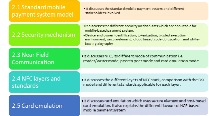
[image:29.595.92.502.446.674.2]This chapter discusses the standard mobile payment system and the different se-curity mechanisms applicable for the same. It discusses Near Field Communica-tion and its different modes of operaCommunica-tion. It discusses the foundaCommunica-tional knowledge needed to understand the rest of this thesis. Figure 2.1 provides an overview of this chapter.
2.1
Standard mobile payment system model
In this section, an overview of the mobile payment system model is outlined in order to understand the characteristics and interactions among engaging parties in mobile-based payment systems. The most common mobile-based payment model consists of five engaging parties.
1. Client is the user with a mobile device that requests to buy a product or service from a merchant.
2. Merchant is the entity which offers the products and services to the cus-tomers and has a payment terminal, i.e. POS, which allows the client to make the payment.
3. Issuer is the institution which manages the bank account of the client. It maintains and manages the funds on behalf of the client.
4. Acquirer is the institution which manages the bank account of the merchant and takes care of the fund transfers.
5. Payment Gateway is an entity which acts as a proxy between the issuer and acquirer. It acts as an interface between payment terminals at the merchant’s place and bank private payment network.
Figure 2.2: The transaction flow and key parties in mobile payment model. Adapted from [15]
the payment gateway which authenticates the card data and transaction amount. The response is sent back to the POS terminal, which provides the receipt to the client. The issuer then transfers the fund to the acquirer and the transaction is complete. Figure 2.2 depicts all the engaging parties and the use case explained above.
2.2
Security Mechanisms
To make mobile payments secure, there are multiple security solutions available in the current mobile payment environment. This section discusses the different security mechanisms currently implemented in the mobile payment applications.
These security mechanisms are:
3. Trusted Execution Environment 4. Secure Element
5. Cloud-based approach (Secure Element on the cloud) 6. Code Obfuscation
7. White box cryptography
2.2.1
Device and owner identification
In the case of mobile devices, it is necessary to verify if the user who is making the payment is the authorized user. One of the common mechanisms is the use of PIN codes. They are usually 4 digits in length, which might be susceptible to brute force attack. Another method is the use of bio-metrics like fingerprint scan-ners or heartbeat sensors. Regarding fingerprint scanscan-ners, they are proven to be insecure as it is relatively easy to copy the fingerprint and fake it1. In the case of
heart beat sensors, they alone are not fully secure as the heart beat is not unique for every individual. These sensors can be made more secure by combining them with other authentication mechanisms. In addition to user authentication, de-vice identification is also necessary. One mechanism is to generate a randomized unique device number which cannot be easily guessed or copied. This number can be protected from being copied by using cryptographic mechanisms like en-cryption. Another proposed solution in [19] is derived credentials in which data required for authentication is generated using protocredential and user-provided secrets like a PIN code. The protocredential is a form of data structure which is stored in the mobile device. When the PIN is provided by the user, the cryp-tographic function uses the PIN and protocredential to generate a key pair for further transactions.
2.2.2
Tokenization
In a mobile-based payment system, the mobile device shares the cardholder data like Primary Account Number (PAN) with the merchant terminal. PAN is the
number found on the payment cards like credit or debit cards. This number is allocated in accordance with ISO/IEC 78121. The next section discusses PAN and other cardholder data in detail.
[image:33.595.160.452.296.364.2]PAN and other card data As defined by Payment Card Industry Data Se-curity Standard (PCI DSS)[20], the overall account data is split into two parts: Cardholder data and Sensitive Authentication Data. Figure 2.3 shows the indi-vidual components.
Figure 2.3: Account Data [20]
PAN A PAN, as defined in ISO/IEC 7812, is usually 16 digits but can be up to 19 digits. The structure2 of a PAN is as follows:
• The first six digits refer to the Issuer Identification Number (IIN) which identifies the institution that has issued the card. Some of the well known institutions are VISA, MasterCard, etc.
• a variable length (up to 12 digits) individual account identifier which is issued by the banking or financial institution.
• The last digit is the check digit which is calculated using Luhn algorithm3. It is used for error detection.
Cardholder name This corresponds to the name of the person who holds the account.
Expiration date This corresponds to the date of the expiration of the card.
1http://www.iso.org/iso/catalogue_detail?csnumber=39699 2https://en.wikipedia.org/wiki/Bank_card_number
Service Code This is a three digit number that specifies acceptance require-ments and limitations for a magnetic-stripe-read transaction. The details of the three digits1 are as follows:
First digit
• 1: International interchange OK
• 2: International interchange, use IC (chip) where feasible • 5: National interchange only except under bilateral agreement
• 6: National interchange only except under bilateral agreement, use IC (chip) where feasible
• 7: No interchange except under bilateral agreement (closed loop) • 9: Test
Second digit
• 0: Normal
• 2: Contact issuer via online means
• 4: Contact issuer via online means except under bilateral agreement
Third digit
• 0: No restrictions, PIN required • 1: No restrictions
• 2: Goods and services only (no cash) • 3: ATM only, PIN required
• 4: Cash only
• 5: Goods and services only (no cash), PIN required • 6: No restrictions, use PIN where feasible
• 7: Goods and services only (no cash), use PIN where feasible
Full track data The magnetic strip has multiple tracks which contain specific information. The details of the different tracks are as follows1:
Track 1
The Track 1 structure is specified as: • STX : Start sentinel ”%”
• FC : Format code ”B” (The format described here. Format ”A” is reserved for proprietary use.)
• PAN : Primary Account Number, up to 19 digits • FS : Separator ”ˆ”
• NM : Name, 2 to 26 characters (including separators, where appropriate, between surname, first name etc.)
• FS : Separator ”ˆ”
• ED : Expiration data, 4 digits or Separator ”ˆ” • SC : Service code, 3 digits or Separator ”ˆ” • DD : Discretionary data, balance of characters • ETX : End sentinel ”?”
• LRC : Longitudinal redundancy check, calculated according to ISO/IEC 7811-2
Track 2
The Track 2 structure is specified as: • STX : Start sentinel ”;”
• PAN : Primary Account Number, up to 19 digits, as defined in ISO/IEC 7812-1
• FS : Separator ”=”
• ED : Expiration date, YYMM or ”=” if not present • SC : Service code, 3 digits or ”=” if not present • DD : Discretionary data, balance of available digits • ETX : End sentinel ”?”
• LRC : Longitudinal redundancy check, calculated according to ISO/IEC 7811-2
CAV2/CVC2/CVV2/CID A Card Security Code (CSC)1 (also referred as card verification data, card verification number, card verification value, card ver-ification value code, card verver-ification code, verver-ification code (V-code or V code), card code verification, or signature panel code) is a security feature for card-not-present payment card transactions. This is usually a 3 digit or 4 digit number present on the card.
PIN A 4 digit number which is used to authenticate the owner of the card.
In tokenization, the sensitive data i.e. PAN, is replaced by a payment to-ken, which is shared with the payment terminal. This token is a surrogate value which is generated in such a way that it does not leak any information about
the actual PAN. This payment token is different for each transaction. The main advantage is that the actual PAN is never shared with the merchant terminals which decreases the overall impact of a successful breach of payment data from the merchant terminal or database. Multiple approaches have been proposed re-lating to tokenization. One of them is proposed by Europay, MasterCard, and Visa (EMV) which provides the specifications for tokenization. In this specifica-tion, the payment token is a 13 to 19 digit numeric value which complies with the rules for a genuine account number. To get an overview of tokenization, one of the use cases for NFC-based mobile payment is explained in the specification[9].
As shown in Figure 2.4, the NFC mobile device either stores the payment token or receives it from the cloud-based storage. This token is shared with the merchant terminal. The Token Service Provider has a token vault which contains a mapping for the token and the corresponding PAN. This PAN is shared with an issuer for validating and completing the transaction. The token can be used with all Cardholder Verification Methods (CVM) but are limited in scope, for example, use of the token can be restricted to a single merchant or duration by putting an expiry value. For the payment token, the issuer needs to perform Identification and Verification (ID&V) steps to make sure the token is mapped to a valid and authorized PAN. There are additional controls like token domains and token assurance level, which help in preventing fraud in the use of tokens. Token domain restricts the use of token to a specific channel (e.g. NFC only), Merchant-specific, digital wallet-specific, or a combination of any of the above. On the other hand, the token assurance level indicates the confidence level that relates to the binding of the payment token and PAN. This level is determined by the result of the ID&V steps.
Figure 2.4: The flow and key elements in token-based payment mechanism [9]
is also susceptible to replay attacks so proper controls need to be in place to validate the authenticity and integrity of the tokens. Also, the implementation of the ID&V steps needs to be correct so that the token requests cannot be forged.
Figure 2.5: Typical Track2 Data vs LoopPay Tokenized Track 2 data [33]
and discretionary data. Figure 2.5 shows the data which is replaced. As suggested in the white paper [33], PAN or some part of PAN is used by merchants for various functions like routing, etc. The replaced data is the token which comprises Token Part Value (TPV) and Token Mode Indicator (TMI). The TPV is generated from the following three elements.
• PAN, Expiry and service code. • Token Sequence Number
• Hash obtained from discretionary data and Loop Account ID.
Using the TPV generation algorithm, the dynamic one-time use token is gener-ated. The token sequence number adds the randomness to the generated token. Figure 2.6 shows the details of TPV generation algorithm. The TMI allows card issuers to identify tokenized cards, validate them and manage the tokens’ life cycles.
The tokenization specification published by PCI DSS [32] shows the sample examples in which the PAN is replaced. Figure 2.7 shows the sample examples.
2.2.3
Trusted Execution Environment
Figure 2.6: Generate TPV [33]
Figure 2.7: Sample token format as defined by PCI DSS [32]
[image:40.595.167.445.148.282.2]Figure 2.8: The normal and secure world environment [7]
2.9 shows the TEE architecture defined by GlobalPlatform [12]. As shown, the mobile operating system is segregated from the TEE kernel. The TEE manages the Trusted Applications as well as secure resources.
Despite its benefits, TEE is susceptible to cloning attacks, side channel at-tacks, changing the behavior of the TEE (e.g. Using buffer overflow attacks) to get access to the sensitive data or make the TEE execute unauthorized services [8]. The major limitation of this mechanism is its high implementation cost as well as lack of programmability.
2.2.4
Secure Element
SE is a tamper-resistant platform which is a secure micro-controller which can store trusted applications and their confidential data like secret keys, PAN, etc. It is present in three forms: UICC, eSE and Micro-SD [10]. Out of the three, UICC is more commonly used.
Figure 2.9: TEE Architecture defined by GlobalPlatform [12]
and the mobile operator needs to provide access to them. To make this happen in a secure manner, Trusted Services Manager (TSM) is used. Once the application is set up along with the data, NFC can be used to communicate with the POS terminals. The NFC antenna has access to the SE and it can only communicate with the mobile payment applications and the data. It uses ISO/IEC 14443 A/B for the communication. The mobile operating system does not have access to the SE. Therefore, the application and data stored in the SE cannot be accessed by any malicious application running in the mobile operating system environment.
Figure 2.10: Software based relay attack [6]
Another possible attack scenario is the relay attack in which an attacker man-ages to install malicious relay software on the smartphone. In addition, the at-tacker places a card emulator close to the POS terminal. The relay software forwards all Application Protocol Data Unit (APDU) to the card emulator and vice versa, thus making the terminal and secure element believe that they are close to each other and are communicating directly with each other. The channel used for relaying the APDU can be Bluetooth, WiFi, etc. Figure 2.10, shows the working of this attack.
2.2.5
Cloud based approach
In cloud-based approach, confidential data can be stored on the cloud servers and can be accessed by the mobile applications when needed. This transfers the security requirements of the mobile device to the cloud service providers. In to-kenization, the token can be generated or stored in the cloud and can be shared with the mobile payment application during transaction requests. However, this requires secure mechanisms to transfer the tokens as well as to store the data on the servers. It is also necessary to have proper authentication mechanisms in place so that unauthorized access to the cloud can be blocked.
needs to have an internet connection, to access the cloud, which might not be always feasible. Without Internet access, the device cannot get the keys as well as tokens. One possible solution is to store this data locally on the mobile device. This mode is called offline authentication. It needs additional security measures to protect the data which is stored temporarily in the device.
2.2.6
Code Obfuscation
Code obfuscation is a technique to protect mobile code from reverse engineering. Lots of mobile applications in the android market are written in Java, which is open to reverse engineering [4]. The reverse engineering allows malicious users to understand the logic of the source code, cryptographic implementation and extract confidential data. It also allows them to modify the source code or inject malicious code into legitimate applications and modify the behavior of the appli-cations. Obfuscated code makes it difficult for the automated tools to de-compile the binary files to generate the meaningful source code. The obfuscated source code makes it difficult to understand the logic. Some of the code obfuscation techniques proposed in [4] are: identifier renaming, control statement insertion or dead code insertion and comment removal. Modifying the class names, at-tributes and method names allows the information about their functionality to be hidden. A second technique inserts an unnecessary control statement to create confusion in the program flow. Lastly, comments are very useful to understand the purpose of the methods or attributes. Removing this information will make it difficult to figure out.
2.2.7
White-box Cryptography
The major issue with the implementation of cryptographic algorithms is the se-crecy of the keys. In white-box cryptography it is assumed that the attacker has complete access to the device but is still unable to uncover the key. In this approach, the keys are embedded in the implementation itself so that they are hidden and there is no need to input the keys. The attacker can copy the implementation and clone it, but the key remains the same. The cloning will consequently be detected if each application uses a different key. In symmetric block ciphers, there are substitution boxes as well as a linear transformation. White-box cryptography allows the creation of the huge lookup table which takes plain text and provides cipher text for the specific key. This transformation can be embedded with random input and output encoding to create ambiguity and make it difficult to figure out the key.
This approach will be useful for mobile payment applications as the separate secure storage requirements for the keys are not needed. However, the major drawback of this approach is to generate a unique application for each device which embeds the unique key. In addition to this, white-box cryptography is limited to symmetric cryptography and it is slower and needs more resources for implementation.
2.3
Near Field Communication
2.3.1
Modes of communication
NFC devices use the electromagnetic induction i.e. Radio Frequency (RF) field generated by the loop antennas to communicate with each other. During the communication, each device can operate as either an active or a passive device. The active device is the one which has its own energy source to generate the RF field while the passive device is the one which does not have its own energy source and uses the RF field generated by the active device to power itself. NFC device supports three modes of communication:
• In Reader/Writer mode, an NFC device behaves as a reader for NFC tags, such as contactless smart cards and Radio-frequency Identification (RFID) tags. It detects a tag immediately in close proximity by using a collision avoidance mechanism. Once detected, it can either read data from or write data to the detected tag. Smart posters are an important application for this mode.
• In Peer-to-Peer mode, two NFC-enabled devices can exchange information between each other. This is the mode used by Android Beam technology. Exchanging photos, business cards and performing money transfer between friends are some of the applications for this mode.
• In Card-emulation mode, an NFC device behaves like a contactless smart card. In this mode, the mobile phone does not generate its own RF field but the NFC reader creates this field instead. Therefore, as long as a mobile platform supports the emulation of protocols surrounding ISO/IEC 14443 that regular contactless cards use, it should be able to function properly. Both Android and Blackberry do this and can therefore be used to emulate contactless cards. In this mode, mobile phones can be used in place of credit cards, debit cards, transit cards, access cards and so on.
2.4
NFC layers and standards
NFC and OSI. In [16], the author explains the different NFC layers as follows:
Physical characteristics This layer provides specifications for the size and temperature operating limits of the NFC device.
Radio frequency interface This layer specifies the protocol used to transform the bits to the physical signal.
Initialization and anti-collision This layer provides the specifications for the initialization of NFC devices when they are in close proximity. It also specifies anti-collision protocols to resolve if there are multiple NFC devices in close prox-imity.
Transmission protocol This layer corresponds to the error detection for reli-able communication.
Application protocol This layer corresponds to the specifications for format-ting of the data.
Figure 2.12 shows the standards involved in contact and contactless cards. (The contactless card refers to one using NFC). In [14], the author describes the different parts of ISO 14443 standards.
ISO 14443-1 The physical characteristics are defined by ISO 14443-1. It define several environmental operating factors that the card must be capable of with-standing without any permanent damage to the functionality. For example, the environment temperature range should be between 0 to 50 degree Celsius.
Figure 2.11: Comparison between NFC layer and OSI layer [16]
ISO 14443-3 This defines the initialization and anti-collision mechanisms im-plemented for Type A and Type B. It defines the anti-collision commands, re-sponses, data frame, and timing.
ISO 14443-4 This defines the high-level data transmission protocols for both type of cards i.e. Type A and Type B. It provides supports for the application layer protocol i.e. ISO 7816-4.
ISO 7816-4 This defines the format of the message being transferred between different NFC devices. The messages transferred are termed as APDU. It defines the APDU command, APDU response, class byte, instruction byte, parameter bytes, data field bytes, status word, basic channel and logical channel [29].
Figure 2.12: ISO standards for contact and contactless cards [14]
Figure 2.13: Android HCE protocol stack [1]
2.5
Card Emulation
[image:49.595.259.353.323.583.2]2.5.1
Host-based Card Emulation
HCE is an alternative solution for SE. As SE adds cost, and UICC SE has access restrictions from mobile operators, there was a need of a solution such as HCE. In Android 4.4 KitKat, HCE was introduced which allows the NFC controller to send the commands for Card Emulation Mode to the HCE service running on the host CPU instead of SE. For example, the user can download a mobile payment application from the store and its AID is registered with the NFC Controller routing table which can route the commands to the Host CPU. This removes the involvement of mobile operators as well as TSM. As SE is considered to be tamper-resistant as well as more secure, HCE needs to have additional security measures especially for isolation and access control to prevent rogue applications on the smartphone easily accessing and exfiltrating payment data.
In Android 4.4, HCE is implemented as a service as it is allowed to run as a background process. Android provides HostApduService class which needs to be extended in the implementation of the bank application. HostApduService class declares two abstract methods that need to be overridden and implemented. The first method is processCommandApdu() which is responsible for handling all the APDUs received from the NFC reader. The second method is processComman-dApdu() which is responsible for sending the response APDUs back to the NFC reader. Method onDeactivated() is called when one of the following cases occur:
• The NFC reader sends another ”SELECT AID” APDU, which the operating system resolves to a different service,
• The NFC link between the NFC reader and your device is broken.
Figure 2.141 shows the flow of APDUs if the device has both HCE as well as
SE. The default route in Android is set to HCE. If there is no route information available for specific AID, it will be sent to HCE instead of SE. The APDUs which are sent to SE are not passed through the HCE service. There is no Android API provided to access the SE from the host CPU. The application implementing the
Figure 2.14: Android operating with both SE and HCE Adapted from [1]
HCE service runs on the Host CPU. Therefore, path 3 defines the route if the AID belongs to the application implementing the HCE service. If the application is hosted on the SE, path 1 is selected. If no information is available for a specific AID, the default route is path 2. The route information is stored in the routing table in the NFC controller.
2.5.2
Different flavors of HCE-based Mobile Payment
Sys-tem
Chapter 3
Secure Element and its different
flavors
This chapter discusses the different forms of secure storage used in the NFC-based mobile payment environment. A comparison of different forms of SE is performed. This chapter also analyzes the benefits and limitations of each of them. This chapter provides the answer to the first research question (Section 1.4) by providing a detailed comparison between different forms of SE. Figure 3.1 provides an overview of this chapter.
3.1
Secure Element
Global Platform1 defines SE as: “a tamper-resistant platform (typically a
one-chip secure micro-controller) capable of securely hosting applications and their confidential and cryptographic data (e.g., key management) in accordance with the rules and security requirements set forth by a set of well-identified trusted authorities” [10]. This platform provides secure storage as well as a secure envi-ronment for the execution of the application. It is the same chip which is present in smart cards like credit cards, transit cards, etc. For mobile devices, this chip is present in three different forms:
Figure 3.1: An overview of Chapter 3
• UICC • eSE • Micro-SD
3.1.1
UICC
UICC is the smart card used in Global System for Mobile Communications (GSM)1 and Universal Mobile Telecommunications System (UMTS) networks2.
It is provided and controlled by MNOs. It usually contains the UICC application and the corresponding data. This application is stored by MNOs which allow secure access to the data stored in UICC. This data contains credentials for veri-fying and authenticating itself to the MNOs. This platform is based on the smart card so it has provision for storing multiple applications and the corresponding data. It therefore provides a suitable platform for storing payment applications. It can store the payment applets and the credentials like keys or PIN codes. As
Figure 3.2: Key capabilities of TSM [21]
access to the UICC is controlled by MNOs, the payment applet and credential need to be provisioned by MNOs in coordination with bank/service providers. This is done with the help of TSM or Over-the-air (OTA) update. This re-stricted access provides a good security level.
3.1.1.1 Trusted Security Manager
3.1.1.2 Over-the-Air provisioning
OTA is a technology which allows the MNOs to remotely manage the application and data installed on the UICC, without any need for a physical connection. OTA is based on client-server architecture in which the MNOs have a back-end server and UICC acts as a client. The standard OTA architecture1 involves the
following components:
• A backend system owned by MNOs to send the message.
• An OTA gateway is responsible for transforming the message so that it can be understood by UICC.
• The Short Message Service Centre (SMSC) receives the message from the OTA gateway and sends the message to the wireless network. A maximum of 160 alphanumeric character can be sent in a message to a mobile phone. If the mobile phone is switched off or is not in the coverage area, the message is stored and sent to the UICC when the mobile is switched on or is in the coverage area of the network.
• A channel which is present between the SMSC and UICC. • A mobile phone containing the UICC.
As discussed in section 3.1.1.1, in the case of TSM, OTA is provided to manage the payment application and credentials remotely. It allows the financial institution to push the software updates or security keys updates directly to the UICC using the TSM platform in a secure manner.
3.1.1.3 Security features and available interface
In UICC, the payment application and credentials are stored within its secure storage space. The mobile phone contains the user interface application which allows the user to perform different tasks like verifying the PIN code and inter-acting with the data stored in the UICC. This application needs an interface to
Figure 3.3: UICC-based SE [26]
interact with UICC using the NFC controller. Figure 3.31 shows the connectiv-ity between the NFC controller and UICC. The interface used for communica-tion between them is Single Wire Protocol (SWP)2. The UICC is connected to
the baseband processor, but there is no connection to the application processor. Therefore, access to the application and data on UICC cannot be achieved by any malicious application running on the application processor. The OTA update can be made using the communication channel between the baseband processor and UICC using a different interface i.e. Inter Process Communication (IPC) interface in the form of AT commands3.
UICC creates a security domain to provision the application of different ven-dors on the UICC. MNOs install their own application in the main security do-main. The main security domain is the Issuer Security Domain (ISD) which is managed by the MNOs. Applications of the service provider (like financial in-stitutions) are provisioned in UICC using TSM. In the case of TSM, multiple security domains are created for each service provider in the UICC. Access to each security domain is restricted using cryptographic keys which are only known
1
https://mobile.mastercard.com/Partner/MobilePayPass/SecureElements
2
http://www.sourcemediaconferences.com/CTST09/PDF09/D/Wednesday/ OuahsineRaphik.pdf
3http://nelenkov.blogspot.nl/2012/08/accessing-embedded-secure-element-in.
Figure 3.4: ISD and SSD hierarchy as suggested by Global Platform [5]
to MNOs and the service provider. A Supplementary Security Domain (SSD) is created for each service provider so that application and data are kept segregated. Figure 3.4 shows the overall layout of the security domains as suggested by Global Platform [5].
3.1.2
Embedded Secure Element
eSE is a smart card which is embedded in the mobile device by the device man-ufacturer. In comparison with UICC, eSE has access control restrictions set by the device manufacturer. Therefore, the application and credentials need to be provisioned by the device manufacturer. The interface which is available for com-munication between the NFC controller and eSE is Near Field Comcom-munication Wired Interface (NFC-WI) [24]. This interface provides three modes of operation:
• OFF mode • Wired mode • Virtual mode
Figure 3.5: Embedded SE [26]
a contactless smart card. These modes are mutually exclusive i.e. two modes cannot be active at a point, so the communication with the eSE is possible either via the contactless interface (e.g., from an external reader) or through the wired interface (e.g., from an Android application). The mode is controlled by the device manufacturer. The WIRED mode can be abused by a malicious Android application if it has root privileges. A malicious application with root privilege can also intercept the traffic between NFC controller and eSE. Figure 3.5 shows the architecture of eSE.
3.1.3
Micro-SD-based SE
Figure 3.6: MicroSD based SE [26]
are very limited ways of remote maintenance. Figure 3.6 shows the architecture of the Micro-SD based SE.
3.2
SE in the Cloud
The limitations of the different forms of SE discussed in Section 3.1 forced compa-nies to look for another location to store the credentials and payment applications. SE in the cloud is one of the solutions which removes the dependency on different parties like MNOs or device manufacturers and allows the card issuer or service provider to completely manage the payment application and the corresponding data. The SE in the cloud is also termed as Virtual SE.
When the NFC-enabled mobile device is placed close to the POS terminal, the sensitive data and application are downloaded from the cloud and stored in the temporary storage in the mobile device. The required data is transferred to the POS terminal to perform the transaction. Once the transaction is complete, the sensitive data downloaded from the cloud is removed from the mobile device. The POS terminal also connects to the cloud server to verify the credentials and other transaction data.
Some advantages of this approach are that it is easier for the financial institu-tion to manage the customer credentials and payment applicainstitu-tions. It also makes it easier to manage virtual SE in the cloud as the storage space in the cloud is quite large compared to the other forms of SE like UICC, eSE, etc. which has limited storage space.
Some of the limitations of this approach are that it needs Internet connec-tivity while making the payment which makes it little challenging for locations which have limited or no connectivity. It adds latency in the transaction time as it rely on the Internet speed which might not be consistent. The device needs to authenticate to the cloud before it can receive the credentials. As the communi-cation between the device and the cloud is over public Internet, it is susceptible to attacks if not implemented correctly.
Another approach which was suggested by EMV1 is tokenization. The
tok-enization is already explained in Section 2.2.2. The benefit of this approach is that the actual card data never leaves the cloud virtual SE. Limited use tokens are transferred and stored in the mobile device’s temporary storage. These tokens are used to perform the transaction. Some of the limitations of this approach include that it is still challenging to provide proper device authentication. Ade-quate protection of the tokens stored in the mobile phone temporary storage is also required.
3.3
Comparison of the different forms of SE
In [3], the author has provided a detailed comparison between different forms of SE i.e. UICC, Micro-SD-based SE and eSE. The author uses the following key attributes for providing the comparison: Security, Re-usability and Standard-ization. Security corresponds to the availability of secure storage and restricted access control. Re-usability means the ease of using the mobile payment solution when the mobile device or SE in the device is changed. Standardization refers to the availability of standards for the communication between the NFC controller and SE, storing and accessing data in SE.
UICC-based SE provides very good security as access to the secure storage containing the payment application and credentials is restricted by MNOs using cryptographic keys. It is also tamper-resistant so that the cryptographic keys cannot be extracted from UICC. It uses security domains to deploy applications from the third parties. Access to the security domains is controlled using cryp-tographic keys which are unique to each domain [13]. In terms of re-usability, UICC-based SE makes it easier for the consumer1 to switch to a different mobile
device. The UICC can be easily removed from one mobile device and plugged into another. The application and credentials are stored in the UICC, so the con-sumer will only need to install the user interface application on the new mobile device. If the UICC is stolen and the consumer receives a new UICC, the appli-cation and credentials will have to be installed again. It is also possible that the consumer switches to a new MNOs which would mean the application and cre-dentials cannot be moved to the new UICC. This effects the re-usability attribute of the UICC-based SE. In terms of standardization, the UICC-based SE has been available in the market for some time and multiple standards are available. SWP is a standard interface for interaction between NFC controllers and UICC. The International Organization for Standardization (ISO)-78162 standard is used for
interaction between application processors and UICC.
eSE provides similar level of security as UICC. The main difference is that with eSE the access control is managed by the mobile device manufacturer while in UICC it is managed by MNOs. eSE also uses cryptographic keys to restrict access to the application and credentials stored. It is also tamper-resistant which provides protection against any leakage of cryptographic keys. In terms of re-usability, it is not good as the eSE is embedded into the mobile device and cannot be removed. Therefore, if the consumer changes the device, the application and credentials have to be installed again in the eSE of the new mobile device. In terms of standardization, eSE has some standards available. NFC-WI is one of the standards accepted for communication between the NFC controller and eSE. However, different mobile device manufacturers might use some other proprietary standard for the same. It will take some time for different mobile device manu-facturers to accept one standard interface.
Micro-SD-based SE is comparatively less secure than UICC and eSE. There is no standard approach defined for managing access control for the application and credentials stored in Micro-SD-based SE. Financial institutions can deploy the application and credentials on the Micro-SD and develop their own access control mechanism1. In terms of re-usability, Micro-SD is better when compared to UICC
and eSE. If the mobile device is changed, the Micro-SD can be moved from the old mobile and can be installed in the new mobile device. The consumer will only be required to install the user interface application on the new mobile device. If the SD is lost or stolen, the financial institutions can provide a new Micro-SD with the application and credentials pre-installed on it. Micro-Micro-SD does not depend on the change of mobile device or MNOs. In terms of standardization, different Micro-SD manufacturers provide support for different interfaces. For example, SD Association uses the SWP interface for communication between the NFC controller and Micro-SD [17]. Micro-SD supports different interfaces and standards but there is a lack of a common approach used by different Micro-SD manufacturers.
As a result of this thesis, the comparison of virtual SE or SE in the cloud
1access control mechanism refers to the security mechanism used to protect the application
Figure 3.7: Comparison of different forms of SE [3]
is presented based on the same three attributes. In terms of security, virtual SE is considered to be secure as the sensitive data is stored on the cloud server. The security relies on the implementation of controls to restrict access to the cloud servers. The communication channel between the cloud server and the mobile device is susceptible to attacks. Therefore, it is important to secure the data while in transit. Authentication of the device is also important as access to the cloud server needs to be verified. In terms of re-usability, virtual SE is comparatively easier to configure when the device is changed, The mobile device has very limited information stored locally and all the sensitive information is stored on the cloud server and it is therefore easier to configure and switch to a new device. In terms of standardization, some standards are available i.e. usage of SSL/TLS1 for communication between the mobile device and the cloud=based
SE, EMV tokenization for storing alias of card data in the mobile device and API2 -based access. Figure 3.7 provides a summary of the comparison between different forms of SE. Overall, UICC is better when compared to other forms of SE. This is also reflected in the current landscape of the NFC-based mobile payment system. A UICC-based payment system is the most prevalent approach. After UICC, the most prevalent approach is SE in the cloud which uses HCE which is discussed in detail in Chapter 4.
1http://www.sans.org/reading-room/whitepapers/protocols/
ssl-tls-beginners-guide-1029
Chapter 4
Host-based Card Emulation
This chapter discusses different security mechanisms and attacks vectors which are applicable for the HCE-based mobile payment system.
This chapter discusses the different attack scenarios which are based on our analysis of the literature and documentation available. The attack scenarios discussed are based on the attack vectors identified by us, as part of this thesis (Only one of them, a hardware-based relay attack on HCE has been tested). This chapter provides answers to the second research question mentioned in Section 1.4. Figure 4.1 provides an overview of this chapter.
4.1
Host Card Emulation
HCE is the card emulation mode in which the functionality of a smart card is emulated without any need for hardware-based SE. The term HCE was first coined by the founders of SimplyTapp, Inc., and describes the ability of the mobile device to act as a smart card and use a channel to communicate between the contactless POS terminal and a remotely-hosted SE containing financial payment card data [18]. SimplyTapp implemented this new technology on the Android operating system1. As well as Android, Blackberry implemented HCE in its
operating system and later Microsoft announced support for HCE in Windows 102. With the introduction of HCE in Android 4.4, multiple entities such as
payment processors VISA and MasterCard started supporting HCE technology [27] [23]. The details of the implementation of HCE in Android 4.4 are explained in Section 2.5.1.
4.2
Security Mechanisms
HCE removes the dependency on hardware-based SE for implementing NFC-based mobile payment systems. The security of this implementation relies on the security permission model of Android3. Therefore, Android has implemented the
following additional security mechanisms which are specific to HCE:
• BIND NFC SERVICE is a system permission which binds with the HCE service. This permission allows only the operating system to
communi-1http://en.wikipedia.org/wiki/Host_card_emulation
cate with the HCE service. This ensures that all the APDUs received by the HCE service come from the operating system, which is received from the NFC controller. In addition, it ensures that the response APDUs are sent back to operating system which are then sent to the NFC controller. This permission provides protection against any sniffing of the APDUs by a malicious application which does not have the required permission. • Screen Off and Device Lock is another security feature implemented in
An-droid. The NFC controller and the application processor are turned off when the device screen is off or is in a locked state1. Therefore, the HCE
service will not work in such case. This protects the device from skimming and unintended interaction with an unknown device without the device owner’s knowledge. By default, the HCE service will work if the device screen is in the locked state as the android:requireDeviceUnlock attribute is set to false. If it is set to true, the device needs to be unlocked to enable the HCE service. This attribute is set in the apduservice.xml file.
4.3
Relay Attack
In the payment system environment, a relay attack can be considered as one of the prevalent attack vectors because of its simplicity, its effects and its ability to circumvent the cryptographic protections. The standard architecture of any relay attack will comprise the following four components:
1. Target Device: This device can be a physical contactless card or a mobile phone with card emulation. One of the assumptions about this target device is that it is physically far away from the POS terminal and is the legitimate holder of the credentials.
2. Mole: This device is a NFC-enabled computing device which is kept in close proximity to the target device. It is under the attacker’s control. It can be in the form of a hardware-based computing device like a mobile device which can act as a NFC reader, or an open-source electronic prototyping platform
Figure 4.2: Standard architecture of relay attack [28]
like Arduino or Raspberry pi with NFC shields. It can be in the form of software (malware), which is installed in the target device itself. This software needs root privilege on the target device to relay the information between proxy and emulated card.
3. Proxy: This device contains an application which acts as a proxy between the target device and POS terminal. This device can be a NFC-enabled mobile device with card emulation. It is also under attacker control. 4. POS terminal: This device is a NFC reader which provides an interface to
the bank payment gateway. The attacker has no control over it.
Apart from the four components discussed above, there is a communication channel between Mole and Proxy. This communication channel can be wired or wireless. This channel is also under the control of the attacker. Figure 4.2 shows the overall architecture of a standard relay attack.
4.3.1
Relay Attack on HCE-based Mobile Payment
Sys-tem
Relay attacks have been performed on SE-based mobile payment systems such as Google Wallet[6]. As a part of this thesis, the relay attack is extended to an HCE-based mobile payment system. The different types of relay attacks and attack scenarios discussed are based on the assumptions and motivations discussed in further sections.
In the case of HCE in Android, the bank application implements the HCE service which is responsible for interacting with the NFC controller. The HCE service binds with BIND NFC SERVICE which ensures that only the system can bind to the HCE service. This allows the HCE service to interact with the operat-ing system which in turn interacts with the NFC controller. The communication between the NFC controller and NFC reader is done using APDUs as defined in the ISO/IEC 7816-4 specification.
4.3.1.1 Hardware-based Relay Attack
In the hardware-based relay attack, the Mole is a hardware device which act as a NFC POS terminal to the Target device. The hardware device has NFC capa-bilities.
To perform a hardware-based relay attack, it is necessary that the Mole is in close proximity to the Target device. Android 4.4 has introduced some secu-rity measures which will prevent the Mole communicating with theTarget device despite being in close proximity to it. The NFC controller and the application processor are turned off completely when the screen of the device is turned off. Therefore, the HCE service will not work when the screen is off. However, if the device screen is on as well as locked, HCE services will still function normally. This is controlled by the android:requireDeviceUnlock attribute in the host-apdu-service tag of the HCE service. By default, device unlock is not required as the HCE service will be invoked even if the device is locked.
Figure 4.3: Wireless Charger
while the attacker needs to skim the target device. Usually, an attacker will want to skim thetarget devicewhen the user is not using thetarget device. For example, when thetarget device is inside the user’s pocket or is left unattended. There are some attack scenarios where these security measures can still be bypassed.
4.3.1.2 Attack Scenario
In this section, one of the attack scenarios will be discussed in which the additional security measures mentioned in the previous section can be bypassed.
• Wireless Charger as a Mole: Wireless chargers allow the mobile device to charge its battery without any need to physically connect the device to a cable. Figure 4.31 shows one of the wireless chargers from Proxi. When a
mobile device is kept on the wireless charger platform, the device screen is enabled for a small time interval showing the notification that the device is charging. The Mole, which is in the form of Arduino with NFC, is trans-planted inside this wireless charger and can utilize the small time interval when the device screen is active to relay the APDUs to the POS terminal. This customized wireless charger can be placed in open environments like Airport terminals, libraries, coffee shops, etc. The transaction flow is as follows:
![Figure 2.2: The transaction flow and key parties in mobile payment model.Adapted from [15]](https://thumb-us.123doks.com/thumbv2/123dok_us/9829738.484246/31.595.119.492.137.358/figure-transaction-ow-parties-mobile-payment-model-adapted.webp)
![Figure 2.3: Account Data [20]](https://thumb-us.123doks.com/thumbv2/123dok_us/9829738.484246/33.595.160.452.296.364/figure-account-data.webp)
![Figure 2.4: The flow and key elements in token-based payment mechanism [9]](https://thumb-us.123doks.com/thumbv2/123dok_us/9829738.484246/38.595.178.401.142.563/figure-ow-key-elements-token-based-payment-mechanism.webp)
![Figure 2.5: Typical Track2 Data vs LoopPay Tokenized Track 2 data [33]](https://thumb-us.123doks.com/thumbv2/123dok_us/9829738.484246/39.595.170.445.147.249/figure-typical-track-data-looppay-tokenized-track-data.webp)
![Figure 2.7: Sample token format as defined by PCI DSS [32]](https://thumb-us.123doks.com/thumbv2/123dok_us/9829738.484246/40.595.155.447.129.457/figure-sample-token-format-dened-pci-dss.webp)
![Figure 2.8: The normal and secure world environment [7]](https://thumb-us.123doks.com/thumbv2/123dok_us/9829738.484246/41.595.165.443.153.304/figure-normal-secure-world-environment.webp)
![Figure 2.9: TEE Architecture defined by GlobalPlatform [12]](https://thumb-us.123doks.com/thumbv2/123dok_us/9829738.484246/42.595.169.425.145.323/figure-tee-architecture-dened-by-globalplatform.webp)
![Figure 2.13: Android HCE protocol stack [1]](https://thumb-us.123doks.com/thumbv2/123dok_us/9829738.484246/49.595.161.449.140.278/figure-android-hce-protocol-stack.webp)
![Figure 2.14: Android operating with both SE and HCE Adapted from [1]](https://thumb-us.123doks.com/thumbv2/123dok_us/9829738.484246/51.595.163.447.144.380/figure-android-operating-se-hce-adapted.webp)
