A Thesis Submitted for the Degree of PhD at the University of Warwick
http://go.warwick.ac.uk/wrap/2735
This thesis is made available online and is protected by original copyright.
Please scroll down to view the document itself.
The use of controlled radical
techniques to form polymer
architectures suitable for use as
Gear Oil Viscosity Modifiers
by
Peter Wright
A thesis submitted in partial fulfilment of the requirements for the degree of
Doctor of Philosophy in Chemistry
Department of Chemistry
Sophocles
“...man will occasionally stumble over the truth, but usually manages to pick
himself up, walk over or around it, and carry on.”
Winston S. Churchill
“Failures are finger posts on the road to achievement.”
Table of Contents ... iii
Abbreviations ... iv
Acknowledgements ... vi
Declaration ... vii
Abstract ... viii
Chapter 1 – Introduction………1
Chapter 2 - Core-first stars as viscosity modifiers synthesised by copper(I)
mediated living radical polymerisation………25
Chapter 3 - Arm first star polymers by copper(I) mediated living radical
polymerisation………..53
Chapter 4 - Phenols as accelerators for SET-LRP………97
ADPA N-phenyl-1,4-phenylenediamine ATRP Atom transfer living racial polymerisation
BA n-butyl acrylate
bipy 2,2-dipyridyl
BMA n-butyl methacrylate
BV40 Absolute viscosity measured on a Brookfield viscometer at
-40°C
C12/15MA A monomer based on Neodol 25 made by Shell
DMAEMA Dimethylaminoethyl methacrylate
DoE Design of experiment
DP Degree of polymerisation
DVB Divinyl benzene
DVM Dispersant viscosity modifier
EGDMA Ethylene glycol dimethacrylate
EHMA 2-ethylhexyl methacrylate
GPC Gel permeation chromatography
KV Kinematic viscosity
LRP Living radical polymerisation
MA Methyl acrylate
Me6TREN Tris(2-(dimethylamino)ethyl)amine
MMA Methyl methacrylate
Mn Number average molecular weight
Mw Weight average molecular weight
NMP Nitroxide mediated polymerisation
NMR Nuclear magnetic resonance
RAFT Radical addition fragmentation chain transfer
OVAT One variable at a time
PAMA Poly alkyl methacrylate
PDI Polydispersity index
SET-LRP Single electron transfer living radical polymerisation
SSI Shear stability index
STY Styrene
t-BuMA t-butyl methacrylate
TMM LRP Transition metal mediated living radical polymerisation
VI Viscosity index
VM Viscosity modifier
VT-I Viscosity temperature improver
Among the many people I wish to thank perhaps the first is David Haddleton.
His constant enthusiasm and optimism helped me battle through those moments
when the chemistry was just not working.
I also thank post-docs past and present for their help, guidance and patience even
when asked the silliest questions.
Particular mention must go to Beppe
Mantovani and Josefina Lindqvist. The polymer group at large, again past and
present, who have provided the answers to many questions and also asked many
good ones of me – I thank you all.
I would like to thank Lubrizol for funding this project and in particular Will
Barton, David Price, Mark Davis and Tim Smith, who either helped set up the
project or have guided me through the industrial angle of this work.
Experimental work contained in this thesis is the original research carried out by the
author, unless otherwise stated, in the Department of Chemistry at the University of Warwick or at Lubrizol’s Chemical Synthesis department, Hazelwood, Derbyshire
between October 2005 and October 2008. No material herein has been submitted for any other degree, or at any other institution.
Results from other authors are referenced in the usual manner throughout the text.
Signed:__________________________ Date:_________________
This project is concerned with the synthesis of Viscosity Modifiers (VMs) for use in gear box oils. The use of amines as precursors for initiators is also of interest due to
their dispersant properties.
Atom transfer radical polymerisation (ATRP) was used to prepare statistical copolymers ofn-Butyl methacrylate and C12/15methacrylate for use as VMs. These copolymers were
first of a linear nature demonstrating that ATRP could be used to polymerise this monomer combination to give well defined polymers with a high degree of control. Thereafter, multi-functional initiators were used to synthesise core first stars with
differing numbers of arms. Three, four, five and eight arm stars were successfully synthesised giving well defined polymers. These polymers were tested by Lubrizol for
their viscometric properties. All were found to give significant improvements versus Lubrizol’s existing linear polymers in almost all respects.
Although the core first stars gave a significant improvement in viscometric properties
the costs of the core are relatively high for the application. Therefore the synthesis of arm first stars via ATRP was carried out. Design of experiment (DoE) was used to aid
in the optimisation process and to interrelate any factors used in the design. The DoE process indicated two relationships between input factors, one of which was defined numerically. A range of polymers were synthesised on a larger scale for testing by
Lubrizol for their viscometric properties. The polymers were found to have exceptional
viscosity properties, compared to the baseline sample.
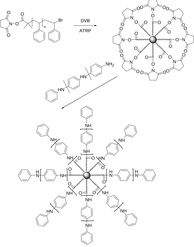
The use of amines as precursors for initiators (forming amide initiators) was
investigated. 4-Aminodiphenylamine (ADPA) was synthesised into an initiator suitable for ATRP and used in several polymerisations. It was found to have very low initiator
efficiency. For this reason Single Electron Transfer Living Radical Polymerisation (SET-LRP) was employed to polymerise methyl acrylate from this initiator with near
100% initiator efficiency. A range of other amide initiators were also successfully used in polymerisations. A new solvent system for SET-LRP was also demonstrated. The
addition of phenol to toluene promoted the disproportionation of Cu(I) allowing SET-LRP to take place. Polymers were synthesised in this solvent mixture with high degrees
Chapter 1
Table of
ContentsTable of Contents ...II List of Figures ... III List of Tables ... III
1 Introduction... 1
1.1 The Oil Additive Industry ... 1
1.2 Viscosity ... 2
1.2.1 Absolute (or Dynamic) Viscosity ... 2
1.2.2 Kinematic Viscosity... 3
1.2.3 Viscosity Index ... 5
1.2.4 Viscosity Index Extension (VIE)... 6
1.2.5 Viscosity-Temperature Improvers ... 6
1.2.6 Shear Stability... 8
1.2.7 Thickening Efficiency ... 9
1.3 Lubricating oil additives ... 11
1.3.1 Dispersants... 11
1.3.2 Viscosity Modifiers ... 14
1.3.3 Transition Metal Mediated Living Radical Polymerisation... 16
1.3.4 Industrial use of ATRP ... 21
1.3.5 Monomer Selection... 22
List of Figures
Figure 1 – Absolute viscosity model ... 3
Figure 2 – Typical log plot of the Kinematic Viscosity against temperature for a lubricating oil... 4
Figure 3 – Graph showing how calculation of Viscosity Index (VI) is based on viscosities at 40°C and 100°C... 6
Figure 4 – The expansion and contraction of a macromolecule depending on the solvent and temperature... 7
Figure 5 – A demonstration of how the shear stability and thickening efficiency change with the molecular weight of the polymer used as a VM. ... 10
Figure 6 – The difference between a soiled piston head on the left, and a new one on the right. ... 11
Figure 7 – Steric stabilisation of a soot particle,the polymer chains prevent the particles getting to close and flocculating... 12
Figure 8 - Representation of how polar groups are incorporated into a dispersant molecule through (A) Polar head groups (B) Polar monomers... 13
Figure 9 - The different methods of anchoring polymeric dispersants onto particles: Polymeric blocks (C, D, E, F) or functional groups (A, B) ... 13
Figure 10 – Plot showing the difference between a base oils viscosity drop (blue) against the same base oil with a viscosity modifier added to it (red). ... 15
Figure 11 - Different structures of polymers obtainable via ATRP ... 16
Figure 12 - Schiff base ligands developed and used at by Haddletonet al.32... 17
Figure 14 – A proposed mechanism of ATRP ... 18
Figure 15 – Four techniques for the removal or reduction in reactivity, of the bromine end group which are detailed further in the text... 20
Figure 16 – Monomers used in this study, chosen to balance the low and high temperature properties. (1)n-butyl Methacrylate, (2) C12/15Methacrylate, (3) 2-ethylhexyl Methacrylate.22
List of Tables
Table 1 – The relative amounts of the different alcohols in Neodol 25 ... 221
Introduction
1.1
The Oil Additive Industry
Lubricating oil additives are designed to improve the efficiency of the oil and to increase the
lifespan of the part(s) being lubricated and of the oil itself. The additive package is devised to enhance an existing property or properties of the base oil or to give it a new property which is
desirable for the application. Typically, lubricating oils for use in cars or lorries would contain:
Additive Role in the Oil
Dispersants Sludge & varnish control
Antioxidants Prohibit oxidation
Antiwear Planetary gear, bushing, thrust washer protection Friction modifier Modify clutch plate and band friction Corrosion inhibitor Prevent corrosion and rust
Seal swell agent Prevent loss of fluid via seals Viscosity Improver Reduce rate of change of viscosity
Pour Point Depressant Improve low temperature fluidity
Foam inhibitor Foam control
Today, the market for the sale of these additive packages is highly competitive with a number of companies selling highly effective products. This research is concerned with the synthesis
of Viscosity Modifiers (VMs) and soot dispersants which represent a significant proportion of the total oil additives market. Therefore any improvement gained through innovation and the
development of new products could be result in significant commercial benefit.
In order to understand how these two additives work and how they might be improved it is first necessary to explore what viscosity is and how it is measured. After this is explained, the
1.2
Viscosity
Viscosity can simply be described as a fluid’s resistance to flow - that is the resistance arising from intermolecular forces and internal friction as the molecules move past each other. In a
situation where two surfaces in motion are fully separated by a fluid the friction is due solely to the internal friction of the liquid; its viscosity.
Different fluids have different viscosities. Water and honey are two liquids with vastly
different viscosities; at ambient temperature water is free-flowing and honey is highly viscous. However, a more interesting observation is that water’s free-flowing nature does not change enough between 5°C and 50°C for the human eye to detect the difference. Honey, on
the other hand, will be almost solid at 5°C and a free-flowing liquid at 50°C. This change in viscosity, however large or small, can be described as the Viscosity Index (VI) which will be
expanded upon later.
The original work describing viscosity of fluids was by Newton in 1668. He stated that “The internal friction (i.e. viscosity) of a fluid is constant with respect to the rate of shear”.1 Newton’s work allowed scientists to later group fluids into two categories; those which obey the above statement, and later came to be described as ‘Newtonian’, and those which do not
are known as ‘Non-Newtonian’. An example of a Newtonian fluid is water; irrespective of the speed of stirring or mixing (or shear) it remains a free-flowing liquid. The viscosity of a
Newtonian fluid is dependent only on temperature but not on shear rate and time. Non-Newtonian fluids’ viscosities are dependant on temperature, time and shear rate. Depending
on how the viscosity changes with time, they can be further defined as either; thixotropic – time thinning, i.e. viscosity decreases with time at constant shear, or rheotropic - time thickening i.e. viscosity increases with time at constant shear. Non-Newtonian fluids can also
be subdivided by their response to shear rate: shear thinning – the viscosity decreases with increasing shear rate, shear thickening – the viscosity increases with increasing shear rate. Polymers are classed as Non-Newtonian fluids.
1.2.1 Absolute (or Dynamic) Viscosity
The viscosity of a fluid can be stated in a number of different ways. Firstly, the absolute or dynamic viscosity. This is measured in Poise (usually stated in Centi-Poise cP), Equation 1. The equation derives from the shear stress and the shear strain (rate of shear). The absolute
area past a parallel surface at a speed of one centimetre per second (U), with the surfaces separated by a fluid film one centimetre thick (h) and is represented in Equation 2. Typically,
the absolute viscosity would be measured using a Brookfield Viscometer.
Figure 1 –Absolute viscosity model
h U A F
Equation 1
This equation can then be rearranged to give the absolute viscosity,η:
Poise s
cm dynes shear
of rate
stress shear h
U A F
/1 2
Equation 2
1.2.2 Kinematic Viscosity
The Kinematic Viscosity (KV- stated in Centistokes, cSt), Equation 3, is the measure of a fluids resistance to flow under gravity. The KV, as shown by Equation 3, is related to the
fluid density. The density of a fluid changes with temperature; it is important to use values for density and absolute viscosity measured at the same temperature when determining KV in this manor. The KV is often measured using a capillary viscometer.
Stokes Density
Fluid
ity Vis Absolute ity
Vis
Kinetmatic cos cos
Stationary Plane
h
A
F
Equation 3
The prediction of the change in KV with temperature is important for assessing oil suitability.
The majority of lubricating fluids give a straight line response on a viscosity temperature plot; when the Walther equation, Equation 4, is used to calculated the KV, the graph plotted from it allows for the prediction of the KV between two points, Figure 2.
40 50 60 70 80 90 100 100
1000
K
in
e
tm
a
ti
c
V
is
c
o
s
it
y
m
m
2/s
TemperatureOC
Figure 2– Typical log plot of the Kinematic Viscosity against temperature for a lubricating oil.
LOGT
c
b
a
KV
Log
Log
10 10(
)
Equation 4
In this equation KV is the kinematic viscosity, a, b and c are constants and machine dependant, while T is the absolute temperature.
However, KV is often measured by using a capillary viscometer so the equation used is a derivation from the above Equation 3, to give Equation 5. Equation 5 can be simplified to
give Equation 6 which shows that the length of the capillary used squared dived by the time taken to move that length gives the KV.
volume
mass
velocity
area
length
force
ity
Vis
Kinematic
cos
time
length
ity
Vis
Kinematic
2
)
(
cos
Equation 6
1.2.3 Viscosity Index
The viscosity index of a fluid describes to what extent its viscosity changes between two
different temperatures and is calculated from the KV. The VI system was established in 1929 by Dean and Davis, who worked for the Standard Oil Development Company (now part of
ExxonMobil).2 The system was developed to show the difference between oils from Pennsylvania, Texas and California. At that time, Pennsylvania oils thinned much less
rapidly than the oils from Texas when subjected to a temperature increase. These Pennsylvania oils were rated 100 on their VI scale. The Texan oils were rated 0. This system
meant that the identification of oils was now possible by measuring its VI by using Equation 7 and Figure 3. However, now that refinement techniques have improved significantly, the same oils which were previously rated 0-10 VI can be prepared with 30-50 VI. Similarly, oils
with higher VI such as from Pennsylvania can often be found with 100+ VI.
A similar problem of differentiating between oils also arose when polymeric additives started to be widely used to improve the viscosity-temperature properties of oils. These additives
have relatively greater effects on the viscosities at high temperature than those at low temperature and therefore increase the VI considerably above 100 VI. This results in
Equation 7 no longer holding true for VI>100. Any additives that improve the VI are defined as viscosity index improvers (VII).
100
H L
U L VI
Equation 7
where L is the 40°C KV of a fictitious oil having the same KV of the test oil at 100°C, defined as having a VI of 0. H is also the 40°C KV of another fictitious oil having the
L
U
H
Figure 3 –Graph showing how calculation of Viscosity Index (VI) is based on viscosities at 40°C and 100°C.
1.2.4 Viscosity Index Extension (VIE)
To overcome this issue of the original Dean and Davis system no longer holding true for VIs over 100, extensional work was undertaken to allow the satisfactory calculation also of these VIs. This new method was designed to provide continuity between the two systems so that an
oil of VI 100 also has a VIEof 100. The VIEvalues can be calculated as described here:
)
1
)
^
10
((
*
140
100
n
VI
EEquation 8
where
100 log
) log (log
KV U H
n
Equation 9
where U and H are as previously described for Equation 7.
After the initial work on the VI system by Dean and Davis,2 Selby, a Senior Research Engineer at General Motors, published a paper on the Non-Newtonian characteristics of
lubricating oils.3 In this work Selby describes the mechanisms by which VMs modify the VI. Selby suggests that “the viscosity of a fluid may be attributed to the difficulty the molecules experience in getting past one another during flow of the fluid mass; the greater the difficulty, the higher the viscosity.”.3 Therefore, upon addition of a high molecular weight polymer (a VM with Mn> 100 000 g mol
-1
), which is spatially quite large, the small molecules of the
mineral oil have a greater difficulty to move past each other and the polymer. The polymer chains also have a high impedance to moving past one another and therefore the solution
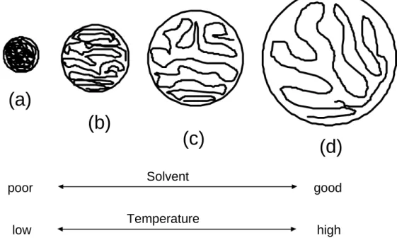
viscosity will increase. The relative size or hydrodynamic volume of the VM molecule should ideally change with temperature. Selby attributes this change to the alteration in
solubility of the VM in the chosen oil. At low temperature, the VM should be sparingly soluble, while at higher temperature it should be completely dissolved. This change in
solubility also causes a change in the hydrodynamic volume. At low temperature, the polymer molecule is contracted to minimise its contact with the oil, while at higher
temperatures it is much less densely packed, ideally fully elongated in the oil, Figure 4.
(a)
(b)
(c)
(d)
Solvent
Temperature
poor
good
low
high
Figure 4 –The expansion and contraction of a macromolecule depending on the solvent and temperature
However, in a case where the VM is soluble in the oil at low temperatures the additive may not act as a VM. In fact, its influence on the viscosity of the oil may well be the same or less
In order to differentiate between an actual VM and a thickener, Selby reclassified a VII as a viscosity-temperature improver (V-TI). These are additives which give a greater viscosity
contribution at higher temperature than low describing the use of Equation 10 to aid in the differentiation between a thickener and a V-TI.
0 0
sp
Equation 10
where µsp= specific viscosity
µ = blend viscosity µ0= base oil viscosity
The viscosity temperature characteristics can be calculated by using Equation 11 where if the ratio for V-T characteristic exceeds 1 the polymer is indeed a V-TI, while when less than 1
the polymer is a thickener. The greater the value above or below 1 shows how effective a thickener or V-TI the polymer is.
40 100 sp sp
stic
Characteri
T
V
Equation 11
In this way Selby suggests that his system for the characterisation of oil VM additives better
separates V-TI from thickeners. However, other than Selby’s discussion of the mechanism of action of VMs most citations of this paper ignore the additional calculations proposed by the
author.
1.2.6 Shear Stability
The shear stability of polymers is an important factor as it is the measure of the ability of the oil/polymer mixture to resist permanent viscosity loss under high shear – the more shear
stable the oil mixture the smaller the viscosity loss when subjected to shear.4 The viscosity of lubricants drops significantly during the early stages of use due to shearing of the VM.5 Generally, lower molecular weight polymers exhibit lower shear rates. However, due to the
lower molecular weights, increasing amounts of additive are needed to obtain the necessary viscosities, increasing the overall cost the additive package. The balance between shear
The shear stability index (SSI) of an oil VM can be defined by the following equation:
100 0
m m
m m SSI
f f i
Equation 12
where:
mi= initial viscosity of lubricant with the viscosity modifier
mf= final viscosity of lubricant after shear
m0= viscosity of the lubricant without the viscosity modifier
The equation can be explained as follows: a VM with a low SSI number is more shear-stable,
while a VM with a high SSI number is less shear stable. Higher molecular weight VMs will have the greatest thickening efficiency for a given weight of polymer but will have the lowest
shear stability (highest SSI).6
1.2.7 Thickening Efficiency
The thickening efficiency (TE) is a measure of a VMs ability to thicken a given oil with
reference to the amount of it added to the oil. Equation 13 shows how the TE is calculated; KV100 is the kinematic viscosity of the oil blend at 100°C, KV oil is the kinematic viscosity of the base oil at 100°C, and the TR is the treat rate, or the amount of the VM added to the oil
as a weight percentage.
TR oil
KV KV Log Efficiency
Thickening ( ( 100))*
Equation 13
The thickening efficiency increases with the molecular weight of a polymer. However, the shear stability decreases as molecular weight increases, Figure 5. Therefore, the molecular
S
h
e
a
r
S
ta
b
ili
ty
T
h
ic
k
e
n
in
g
E
ff
ic
ie
n
c
y
Molecular Weight
1.3
Lubricating oil additives
1.3.1 Dispersants
Dispersants are used in automotive applications to keep impurities, particularly those formed during the use of mechanical devices such as automatic transmissions, internal combustion
engines and brake fluid, in suspensions rather than allowing them to accumulate as sludge or other deposits on the surfaces of the lubricated parts. The insoluble materials are often formed by oxidation and other mechanisms during the use of the oil. Dispersants prevent the
agglomeration of soot particles, therefore reducing increases in viscosity of the lubricating oil upon use.
Figure 6 –The difference between a soiled piston head on the left, and a new one on the right.
The mechanism by which they prevent agglomeration is by either electrostatic or steric
stabilisation,7 Figure 7. Dispersants usually use steric stabilisation as they are non-ionic species. This is where the steric interactions of the polymer chains attached to the particles
cause the particles to repel one another preventing agglomeration. They also prevent corrosion by these often highly polar by-products. Although a dispersants primary role is to
prevent deposition of soot, they must also have other properties in order to function effectively. These properties include oxidative and thermal stability, good low temperature
properties i.e. maintenance of low viscosity and the dispersant head group not degrading seals of the unit, gear box/engine that it is in.4, 8 Those dispersants that are not oxidative or thermally stable will firstly break down, reducing its ability to suspend soot and sludge
Figure 7 –Steric stabilisation of a soot particle,the polymer chains prevent the particles getting to close and flocculating.
Dispersants can be separated into two categories: (1) Dispersant viscosity modifiers (DVM),
or (2) Dispersant polymers. In DVMs, the dispersency and viscosity modifying properties are combined into the same product. They are derived from hydrocarbon polymers, often olefin
or (meth)acrylate based, of molecular weights between 25,000 and 500,000 g mol-1. Alternatively, polymers used to make DVMs include olefin copolymers such as
ethylene-propylene copolymers9, ethylene-propylene-diene copolymers11, 12and polymethacrylates13-17, styrene diene rubbers10 and styrene-ester copolymer19. Dispersant polymers have a low molecular weight, usually between 3000 and 7000 g mol-1 and do not usually have any additional properties besides dispersing insoluble materials.
Polymer-based dispersants have been used to stabilise paints,20, 21ink systems22, 23and carbon impurities in automotive applications.9, 24 The system has a three component structure which combines the different requirements, Figure 8, which is summarised here.
1. The anchoring group, which must be capable of strongly attaching, via different methods, to the surface of particles.
2. The polymeric chain, which must dissolve the polymer in the desired solvent and stabilise the particle it is anchored onto.
3. A linking group between the polymeric chain and the polar anchoring group.
generally derived from amines and are usually basic in nature whilst oxygen-based groups are derived from alcohols and are neutral.7
Connecting group
Polar group
Hydrocarbon group
A
B
Figure 8 -Representation of how polar groups are incorporated into a dispersant molecule through (A) Polar head groups (B) Polar monomers
The two ways of incorporating these properties into polymers are shown in Figure 8. The anchoring groups can either be by polar head groups or as part of the polymeric chain. The
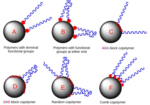
solvating part is always a polymer with six common configurations for solvation, Figure 9.
Polymers with terminal functional groups
A
B
Polymers with functional groups at either end
C
ABAblock copolymer
D
BABblock copolymer
E
Random copolymer
F
Comb copolymer
Figure 9 -The different methods of anchoring polymeric dispersants onto particles: Polymeric blocks (C, D, E, F) or functional groups (A, B)
Each type of interaction has its own distinct advantages with methods A and C being
considered to be the optimum. This is because they prevent flocculation by bridging of the particles by the dispersant, where a polymer chain is anchored onto two particles. However,
particles surface allowing for greater dispersion. Methods B-F all have multiple anchor points and give a greater possibility of anchoring successfully onto a particles surface,
however bridging of particles is more likely.
The dispersing group almost always contains secondary nitrogen and often aromatic groups as
these are the most effective at binding to soot and sludge. Although the exact mechanism is not known, it is likely to be a combination of hydrogen bonding of the nitrogen to the soot
surface; soot has a significant amount of carboxylic acid groups on its surface, and electrostatic interactions.11 Soot is known to have a significant amount of aromatic groups in its structure along with carboxylic acids and hydroxyl groups and thereforeπ-πstacking and acid/base interactions can be used to absorb the dispersant head groups onto the surface.
Polar head groups used as dispersants are wide ranging from amines such as ethylenediamine8, through to dyes such as disperse orange 3.24 Maleic anhydrides,12 succinimides,13, 14Mannich bases products,27, 28carboxylic functionalities13have been used to react with the desired amine functionality - aromatic amines13, 14 such as phenyl-1,4-phenylene diamine31, 32 and other amines.12, 14 A further way of anchoring polymeric dispersants onto soot/sludge is using a monomer which has nitrogen incorporated in it such as dimethylaminoethyl methacrylate or dimethylaminoethyl methacrylamide. 15 Sludge is best dispersed by non-aromatic amines for miscibility reasons.
The nature of the polymer chain is very important for dispersants. If the chains are not long enough and are not soluble enough, the dispersant will not provide a thick enough barrier to
prevent flocculation. This will cause an increase in viscosity and a decrease in performance. Alternatively, if the chains are too long, then the chain will collapse onto the particles surface
allowing it to aggregate or flocculate. Ideally, the polymer chains should be of a length where it can move freely in solution.
1.3.2 Viscosity Modifiers
Viscosity modifiers (VM, viscosity improver, VI, or viscosity index improver, VII) reduce the
extent of the increase in kinematic viscosity as the temperature is lowered, or reduce the extent of the decrease in kinematic viscosity as the temperature is raised, or both.4 They should have good thickening capability while remaining cost effective, be shear stable and
have minimal deposits at high temperature.6 This should mean that the oil maintains a more consistent viscosity over a broad range of temperatures. If the oil is too thin then it is moved
damage. When the oil is too viscous it either does not flow into the interface causing certain surface damage, or it consumes too much energy which is converted to heat and the system
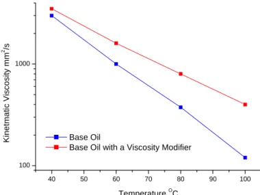
can overheat. The kinematic viscosity is usually measured between 40°C and 100°C and a graph plotted to show the change over the temperature range, Figure 10. The effect of adding a VM is demonstrated with the viscosity variance being smaller over the same temperature
range.
40 50 60 70 80 90 100
100 1000
Base Oil
Base Oil with a Viscosity Modifier
K
in
e
tm
a
ti
c
V
is
c
o
s
it
y
m
m
2 /s
TemperatureOC
Figure 10 –Plot showing the difference between a base oils viscosity drop (blue) against the same base oil with a viscosity modifier added to it (red).
A simplified explanation for this phenomenon is that the polymer-oil interaction at low
temperature is minimal but increases as temperature rises. This interaction of the polymer
with the base oil at higher temperatures increases the hydrodynamic volume of the polymer causing an increase in the effective volume fraction of the VM. This leads to an increase in lubricant viscosity.6
VM’s have previously been made from polyolefin,17, 18polyisobutylene16-20and more recently poly(alkyl methacrylate)s.14-16, 39 They are usually linear, although stars and other branched architectures have been used. The stars have exceptional low-temperature properties but
undergo more permanent viscosity loss under severe conditions.6 The alkyl methacrylates are of particular interest as they are a blend of chain lengths from C11 to C18 to give the desired
properties, e.g., de-waxing, solubility and VM. Carbon chains with 8 to 13 carbons give solubility in hydrocarbon solutions. Long chains of 14 or more carbons give de-waxing
by varying the copolymer composition, particularly low temperature ones. The desirable property of the poly(alkylmethacrylates) (PAMAs) are the ability to contribute relatively little
viscosity at lower temperatures but have a much higher contribution to viscosity at elevated temperatures. 22 They have been previously made by free radical polymerisation. However, more recently living radical polymerisation techniques such as radical addition fragmentation
chain transfer (RAFT), nitroxide mediated polymerisation (NMP) and TMM LRP (transition metal mediated living radical polymerisation or commonly known as atom transfer radical
polymerisation – ATRP) have all shown great potential for making PAMAs due to their molecular weight control and narrow PDIs. The VM block can be made into a block
copolymer with the dispersant block to reduce the number of components that are needed in the final product.
1.3.3 Transition Metal Mediated Living Radical Polymerisation
The non-linear structures that are of interest for VMs are not easily accessible by
conventional free radical polymerisation. However, living radical techniques can be used to access a variety of non-linear structures. The polymerisation technique being used for this
project, TMM LRP has seen extensive research in the 13 years since it was originally published by Sawamoto23and Matyjaszewski24in 1995. Pioneering work on this system used Ru(II) and Cu(I) catalysts respectively.23,24 ATRP has been further developed to use different transition metals as catalysts including low valent iron, 25, 26 palladium, 27 rhodium28 and nickel.29
Block
Homo polymer copolymer Statistical
Composition
Graft copolymer
Structures
Linear
Star
Comb
The appeal of this chemistry is the high degree of molecular weight control, the variety of structures that can be synthesised, Figure 11, and low PDI of the products giving more
mono-disperse properties (PDI < 1.2). In addition each polymer chain retains a terminal initiating group giving α-functional polymers. ATRP is relatively insensitive to impurities such as water, making it a robust technique for scale up to industrial levels of production. The
polymerisations can be carried out in bulk or in solution. A wide range of solvents can be used, including: toluene, dimethoxybenzene (DMB), diphenyl ether (DPE), ethylene
carbonate, acetonitrile, N,N-dimethylformamide (DMF), acetone, most alcohols (especially methanol and isopropanol), water, benzene and anisole.30 The solvent can be tailored to the monomer system being polymerised. Depending on the solvent being used, the ligand can also be altered to ensure that the transition metal is soluble in the chosen solvent. The ligands
can vary dramatically from the original diamine reported by Matyjaszewskiet al. in 1995,31to the Schiff base ligands, Figure 12, reported by Haddletonet al. in 1998.32
R=Et, n-Pr, n-Bu, n-Pen, n-Hex, n-Oct, n-Non, n-Octadec
N
N R
Figure 12 -Schiff base ligands developed and used at by Haddletonet al.32
All the features mentioned make ATRP an attractive technique relative to anionic
polymerisation which requires exceptionally pure reagents, very clean glassware along with low temperatures (often < –78°C) causing difficulty in industrial scale up for
commercialisation. It also gives the molecular weight control which free radical processes do not have.33 Unfortunately, ATRP does have several drawbacks. Transition metals tend to be difficult to remove from the final product which is consequently contaminated with the metal to some extent. Also, the presence of oxygen has an adverse effect on the metal catalyst causing the rate to be abnormally slow and so the evacuation of oxygen is an important part of
this chemistry. The reactions are sensitive to acidic impurities which have a negative effect on the polymerisation.
ATRP can be described as living if the rate of termination/chain transfer events is equal to
zero. In a living polymerisation there is a linear increase in the number average molecular weight (Mn) as conversion increases. The first order kinetic plot should also be linear,
indicating a constant concentration of propagating species, Figure 13. Since there is the same concentration of radical species throughout the reaction and termination equals zero, after
The constant concentration of propagating species is brought about by a redox equilibrium
between oxidation states of the transition metal. The metal should have 2 accessible oxidation states separated by 1 formal charge, have good affinity for halogens and should
have a coordination sphere that can expand to accommodate a halogen ligand.34 In the case of copper, Cu(I)X (X = Br or Cl, usually Br) is added to the polymerisation. Homolytic
cleavage of the C-X bond of the initiator results in a radical or radical-like species. The initiator is then able to initiate polymerisation. Ideally, the initiation is at least as fast as propagation and the transfer and termination negligible, therefore the number of growing
chains is constant and equal to the original initiator concentration. When the rate of initiation is faster than or equal to the rate of propagation, the obtained polymers have narrow PDI
(~1.1). The free halogen is then captured by the copper complex causing it to be oxidised to the Cu(II) state. The transfer of the halogen between the end-capped position on the end of
the polymer chain and the copper complex is fast and the equilibrium such that termination is a minimum, Figure 14.
R X MyLn
ka
kd
My+1LnX
R
kp R'
Termination
kt
Figure 14 – Aproposed mechanism of ATRP
There are cases where the rate of initiation is too fast e.g. amide initiators. This type of polymerisation commonly results in very low initiator efficiencies and slightly broader
Figure 13 -The two graphs plotted to test for a living polymerisation, a first order kinetic plot and number average molecular weight (Mn) evolution with conversion of monomer
Mn
% Conversion
kp[Pol*]
ln
([
M
]0
/[
M
])
PDIs.35 The low efficiency causes the molecular weight to be much higher than predicted. Very little work has been done on how to increase the efficiencies of this type of initiators
although work by Haddletonet al.36details how the due of a short induction period at ambient temperature and replacing Cu(I)Br with Cu(I)Cl reduces the rate of initiation and increases the efficiency of the initiator.
ATRP has been widely used to produce polymers that can be used for applications ranging
from polymer-drug bioconjugates,37 mucoadhesive polymers for drug delivery,38 to conjugation to carbon nanotubes for numerous applications.39 It has not, however, been widely used to produce polymeric additives for fuels or lubricating oils, specifically DVMs or VMs. Traditionally, free radical polymerisation has been used to produce polymers for use in
fuels and lubricating oils. Using free radical polymerisation is relatively easy to approach 100% monomer conversion, it can be run in bulk and that there are low levels of volatile
organics (VOC’s) to remove post reaction.33 However, polymers from free radical processes tend to have broad PDI (typically PDI > 2)40causing the bulk properties of the polymer to be less defined. There is also little architectural control. The strengths of ATRP have not been fully utilised as yet for commercial applications. Among the reasons for this are high metal (and to a lesser extent ligand) content in the product and an elevated concentration of
halogens particularly in the lower molecular weight polymers. Halogens containing compounds that will be used in formulations that are handled by metallic devices such as
pumps, tubing, containers or spraying devices can cause corrosion problems.41
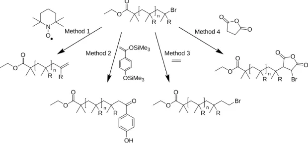
Removal of the halogen end-group has been attempted by several approaches. Several were detailed by Haddletonet al.using a range of approaches.42 Method 1 involves the homolysis of the ω-CBr bond with a subsequent reaction, via coupling or disproportionation, with an external radical species such as TEMPO. Organotin compounds can be used, specifically tributyltin hydride to remove the halogen leaving a hydrogen atom at the ω-terminus.43
Method 2 utilizes monomers that are able to fragment after undergoing radical addition to the polymer chain such as trimethylsilyl enol ethers used as quenchers, previously reported by
Sawamoto et al.44 This reaction gives polymers with ω-ketone functionality and the corresponding trimethylsilyl halide as a by-product. Reaction with allyl bromide under similar
conditions yields an allyl-functionalized polymer material as a result of its addition and subsequent fragmentation, that is, the elimination of a bromide radical. Method 3 involves
the reaction of the polymer chain with ethylene. This results in the formation of a primary carbon-bromine bond which is much less reactive in ATRP. Method 4 is the reaction of a
carbon double bond containing compound or LPDP compound”41the resulting in a secondary carbon on the end of the polymer chain allowing elimination of HBr to occur.
O Br O R R n O O R R n O O R R n O OH O O R R n Br O O R R n O O O Br Method 1
Method 2 Method 3
Method 4 N O O O O OSiMe3 OSiMe3
Figure 15 –Four techniques for the removal or reduction in reactivity, of the bromine end group which are detailed further in the text.
ATRP, as already described, can be carried out in bulk (absence of solvent), although does
have ligand and copper to remove from the polymer before it can be used commercially. For gear oil applications the copper levels would have to be parts per million (ppm) as elevated
copper levels are a sign of corrosion/degradation of the gears. Copper can be removed by bubbling the reaction mixture with air immediately following the polymerisation process whilst cooling. This aids oxidation of the Cu(I) to Cu(II) and precipitation of less soluble
copper(II) salts. The reaction mixture is then passed over alumina, silica, ion exchange resins or activated carbon removing the copper.63 In work by Dubois et al.63 they showed the relative effectiveness of these different copper removal processes. They found that for poly(dimethyl aminoethyl methacrylate), which binds to copper, the most effective method
was sulfonated ion exchange resin, although it was quite a slow process. After filtration, the polymer can be precipitated into, in the case of PMMA, methanol with 5% sulphuric acid
which removes residual copper salts. This precipitation process has been developed and used exclusively at Warwick. However, the extensive work up required to remove the catalyst is
both expensive and wasteful. The Schiff base ligands used at Warwick are not always easily removed and can give the polymers a yellow tinge.
In an attempt to find a catalyst that is homogeneous at reaction temperature, but insoluble at ambient temperature several groups varied their ligand structure.
< 1.2 and the catalyst showed good activity even after being recycled twice. Barréet al. took a different approach in that they used highly hydrophobic groups on their ligands to render
them insoluble in highly polar media causing them to precipitate in high yield, ~97%.46 They found that the copper concentration was approximately 200 ppm, ~190 ppm more than by filtering existing complexes with basic alumina.49
Other methods have been attempted to reduce the copper levels in the polymers made by
ATRP. One approach was to attach the ligand onto a solid support.47 This allows the ligand and most of the copper to be removed by a filtration process. However, when the solid
supported ligand is reused, its activity drops reducing its effectiveness at catalysing the polymerisation.47 The PDI also broadens to ~1.4. Although this is a good method for keeping the work-up of the polymers to a minimum, the advantages of ATRP are reduced by using the solid supported ligand and is therefore not as advantageous as anticipated.
Duquesne et al. have attempted to optimise the conditions for using solid supported catalysts.67 They investigated the effect of changing, among other factors the temperature of polymerisation, catalyst concentration, ligand, monomer concentration, ligand to catalyst molar ratio and the influence of catalyst recycling on further polymerisations. They found that although the PDI could be narrowed and good molecular weight control improved upon
previous work, the polymerisations were still not as controlled as homogenous catalysts.
1.3.4 Industrial use of ATRP
A number of companies have taken advantage of the benefits of ATRP. RohMax Additives48 has used it to synthesise copolymers which act as pour point depressants for lubricating oils.
They polymerised using a 50:50 mixture of mineral oil:toluene as their solvent mixture to give molecular weight control and allow ease of handling of the end product.49 This polymerisation process has also been used by CIBA Speciality Chemicals Inc50to synthesise phenolic antioxidants for fuels and lubricating oils.51, 52 They take particular interest in block copolymers and end group modification to remove the halogen as they are undesirable in
polymers for applications with high temperatures, since elimination of hydrogen halide may
occur at elevated temperature.52 The double bond formed is very sensitive to reactions with oxygen, which in the case of CIBA Speciality Chemicals antioxidants reduces their effectiveness. The hydrogen halide released may also react with other functionalities in the
started using several living radical polymerisations to synthesise high molecular weight multi-arm stars54for viscosity modifying applications. These processes include NMP, RAFT along with ATRP. They describe how linear polymers are made and then a cross linking agent, as discussed in more detail in chapter 3, is added causing star formation.
1.3.5 Monomer Selection
For this work certain monomers were chosen to give optimal performance as a VM. The
three monomers used were C12/15 methacrylate (C12/15MA), n-butyl methacrylate (BMA) and
2-ethylhexyl methacrylate (EHMA), Figure 16. The C12/15MA is used to provide solubility in
the oil, while the addition of either BMA or EHMA prevents the polymer solidifying when the longer alkyl chains co-crystallise with the wax in the lubricating oil at low temperature.
The C12/15MA is made from Neodol 25, an alkyl alcohol from Shell Chemicals and modified
by Lubrizol to a methacrylate, Table 1 (2).
O
O O O
10-13
O O
1 2 3
Figure 16 –Monomers used in this study, chosen to balance the low and high temperature properties. (1)n-butyl Methacrylate, (2) C12/15Methacrylate, (3) 2-ethylhexyl Methacrylate.
The ratio of monomers used for the synthesis of the stars was decided by Lubrizol. This ratio
was 70 wt % C12/15MA, 30 wt % BMA or EHMA (close to a 1:1 molar ratio), which is known
to provide good viscosity-modifying properties at a wide range of temperatures.
Chain Length Percentage of mixture
C11 and shorter <1
C12 21
C13 29
C14 25
C15 25
C16 and longer <1
Table 1 –The relative amounts of the different alcohols in Neodol 2555
change dramatically from MMA to dodecyl methacrylate (structurally closed to C12/15MA).
Therefore a statistical copolymer is expected to be formed
Monomer kpL mol
-1
s-1 Reference
Methyl Methacrylate 1620 56
n-Butyl Methacrylate 1930 57
2-Ethylhexyl Methacrylate 2180 58 Dodecyl Methacrylate 2390 76, 77
2
References
1. I. Newton,The mathematical principles of natural philosophy., printed for Benjamin Motte, London, Printed 1729.
2. E. W. Dean and G. H. B. Davis,Chem. and Metall. Engng, 1929,36, 618-9. 3. T. W. Selby,ASLE, 1958,1, 68-76.
4. S. Srinivasan, Y. S. Song, J. S. Strukl, P. Growcott, P. G. Griffin and A. Duggal, 2005-17288, 1637580, 2006.
5. M. J. Covitch, J. Weiss and I. M. Kreutzer,Lubrication Science, 1999,11, 337-64. 6. E. A. Bardasz and G. D. Lamb,Chemical Industries, 2003,90, 387-428.
7. S. Q. A. Rizvi,Chemical Industries, 2003,90, 137-70. 8. A. S. Oldfield and D. J. Irvine, WO2006054045, 2006. 9. K. Okada and R. Kaneshige, WO2000034420, 2000.
10. D. Vargo, D. Visger, B. Schober, S. Patterson, P. Mosier, C. Friend, J. Pudelski, M. J. Covitch, D. Price and et al., WO2005103093, 2005.
11. E. Ghzaoui, M. Lindheimer, A. Lindheimer, S. Lagerge and S. Partyka,Colloids Surf., A, 2004,233, 79-86.
12. C. J. Kolp, P. A. Lewis and J. G. Dietz, US6165235, 2000. 13. T. E. Nalesnik, US4863623, 1989.
14. B. A. Grisso, D. A. Hutchison and R. T. Dittmeier, EP1574559A1, 2005. 15. J. T. Loper and R. M. Sheets, US2005143265, 2005.
16. J. D. Burrington, S. L. Bartley, P. W. Pike and C. J. Kolp, WO2001098387, 2001.
17. M. J. Covitch, J. K. Pudelski, C. Friend, M. D. Gieselman, R. A. Eveland, M. G. Raguz and B. J. Schober, US2006025316, 2006.
18. J. N. Vinci, C. D. Tipton and R. W. Cain, WO2002083825, 2002.
19. T. S. Coolbaugh, F. C. Loveless, J. E. Marlin, II, D. N. Matthews and J. M. Klosek, WO2000034421, 2000.
20. B. P. Gracey and D. J. Moreton, EP889113, 1999. 21. M. J. Covitch,Chemical Industries, 2003,90, 293-327. 22. B. G. Kinker,Chemical Industries, 2003,90, 329-53.
23. M. Kato, M. Kamigaito, M. Sawamoto and T. Higashimura,Macromolecules, 1995,28, 1721-3.
24. J.-S. Wang and K. Matyjaszewski,Journal of the American Chemical Society, 1995,117, 5614-15.
25. T. Ando, M. Kamigaito and M. Sawamoto,Macromolecules, 1997,30, 4507-10.
26. K. Matyjaszewski, M. Wei, J. Xia and N. E. McDermott,Macromolecules, 1997,30, 8161-64. 27. P. Lecomte, I. Drapier, P. Dubois, P. Teyssie and R. Jerome,Macromolecules, 1997,30,
7631-33.
28. V. Percec, B. Barboiu, A. Neumann, J. C. Ronda and M. Zhao,Macromolecules, 1996,29, 3665-8.
29. C. Granel, P. Dubois, R. Jerome and P. Teyssie,Macromolecules, 1996,29, 8576-82. 30. K. Masami, A. Tsuyoshi and S. Mitsuo,Chemical Reviews, 2001,101, 3689-745. 31. J.-S. Wang and K. Matyjaszewski,J. Am. Chem. Soc., 1995,117, 5614-15.
32. D. Haddleton, D. Duncalf, D. Kukulj, A. Heming, A. Shooter and A. Clark,J. Mater. Chem., 1998,8, 1525-32.
33. K. Matyjaszewski and S. G. Gaynor,App. Pol. Sci., 2000, 929-77. 34. K. Matyjaszewski and J. Xia,Chem. Rev., 2001,101, 2921-90.
35. A. Postma, T. P. Davis, G. Moad and M. S. O'Shea,React. Funct. Polym., 2006,66, 137-47. 36. A. Limer and D. M. Haddleton,Macromolecules, 2006,39, 1353-58.
37. F. Lecolley, L. Tao, G. Mantovani, I. Durkin, S. Lautru and M. Haddleton David,Chem. Commun., 2004, 2026-7.
38. S. Keely, A. Rullay, C. Wilson, A. Carmichael, S. Carrington, A. Corfield, D. M. Haddleton and D. J. Brayden,Pharm. Res., 2005,22, 38-49.
39. H. Kong, C. Gao and D. Yan,J. Am. Chem. Soc., 2004,126, 412-13. 40. C. J. Hawker, A. W. Bosman and E. Harth,Chem. Rev., 2001,101, 3661-88. 41. G. J. McCollum, J. B. O'Dwyer and S. Coca, WO9954365, 1999.
43. V. Coessens and K. Matyjaszewski,Macromol. Rapid Commun., 1999,20, 66-70. 44. T. Ando, M. Kamigaito and M. Sawamoto,Macromolecules, 1998,31, 6708-11. 45. Y. Shen, S. Zhu and R. Pelton,Macromolecules, 2001,34, 3182-85.
46. G. Barre, D. Taton, D. Lastecoueres and J.-M. Vincent,J. Am. Chem. Soc., 2004,126, 7764-65.
47. D. M. Haddleton, D. Kukulj and A. P. Radigue,Chem. Commun., 1999, 99-100. 48. http://www.rohmax.com/en/oiladditives, Accessed 9th December 2005.
49. M. Scherer and J. Souchik, US6391996B1, 2002. 50. http://www.cibasc.com/, Accessed 9th December 2005.
51. B. Camenzind, P. Dubs, P. Haenggi, R. Martin, A. Muehlebach and F. Rime, WO2003095512, 2003.
52. B. Camenzind, P. Dubs, P. Hanggi, R. Martin, A. Muhlebach and F. Rime, US0272717A1, 2005.
53. http://corporate.lubrizol.com/, Accessed 12th June 2006.
54. D. Visger, M. Davies, D. Price, M. Baum and B. J. Schober, WO2006047398, 2006. 55.
http://www.shell.com/home/content/chemicals/products_services/our_products/alpha _olefins_detergent_alcohols/neodol/product_data/neodol_product_data.html, Accessed 6th June 2009.
56. S. Beuermann, M. Buback, T. P. Davis, R. G. Gilbert, R. A. Hutchinson, O. F. Olaj, G. T. Russell, J. Schweer and A. M. Van Herk,Macromol. Chem. Phys., 1997,198, 1545-60. 57. S. Beuermann, M. Buback, T. P. Davis, R. G. Gilbert, R. A. Hutchinson, A. Kajiwara, B.
Klumperman and G. T. Russell,Macromol. Chem. Phys., 2000,201, 1355-64.
58. R. A. Hutchinson, S. Beuermann, D. A. Paquet, Jr. and J. H. McMinn,Macromolecules, 1997,
Chapter 2
-Core-first stars as viscosity
modifiers synthesised by copper(I)
mediated living radical
Table of Contents
Table of Contents ... II
List of Figures ... III
List of Tables... V
1
Introduction ...26
1.1
Core First stars by copper(I) mediated living radical polymerisation
(ATRP)...26
1.2
Halo Ester Initiators ...26
1.3
(Haloalkyl) benzene initiators ...28
1.4
Sulphonyl Chloride initiators ...29
1.5
Shear Stability of Core First Stars...30
2
Results and Discussion...32
2.1
Overview of the synthesis of core-first multi-arm star polymer ...33
2.2
Synthesis of the linear polymers ...35
2.2.1 Synthesis of the 4-Methylphenyl 2-bromoisobutyrate initiator ... 35 2.2.2 Synthesis of the Polymers ... 352.3
Synthesis of a three arm star polymer ...37
2.3.1 Synthesis of three arm initiator ... 37 2.3.2 Synthesis of the Polymers ... 372.4
Synthesis of a four arm star polymer ...39
2.4.1 Synthesis of a four arm initiator ... 39 2.4.2 Synthesis of the Polymers ... 392.5
Synthesis of a five arm star polymer...41
2.5.1 Synthesis of the five arm initiator ... 41 2.5.2 Synthesis of the Polymers ... 412.6
Synthesis of an eight arm star polymer ...43
2.6.1 Synthesis of an eight arm initiator... 43 2.6.2 Synthesis of the Polymers ... 433
Conclusions ...46
4
Experimental ...47
4.1
Materials and Instrumentation...47
4.2
Copper mediated living radical polymerisation – General procedure .47
4.3
Purification of copper (I) bromide ...48
4.4
Synthesis of
N
-Propyl-2-pyridiylmethanamine...48
4.5
Synthesis of
N
-Octyl-2-pyridiylmethanamine ...49
4.6
Synthesis of 1,3,5-Tri-O-isobutyryl bromide benzene...50
4.7
Synthesis of
List of Figures
Figure 1 – Multi-arm organic halo-ester initiators for ATRP ... 26 Figure 2 – Core-cross linked star polymers synthesised from In5... 28
Figure 3 - Multi-arm organic and inorganic (Haloalkyl) benzenes initiators for ATRP. 28 Figure 4 - Multi-arm organic sulphonyl chloride based initiators for ATRP... 29
Figure 5 – The terminating agent, used by Percecet al.,which can be transformed into a di-functional initiator suitable for ATRP.17... 30 Figure 6 - Chemical Structures of the 6-arm PMMA stars compared for shear stability19
... 31 Figure 7 – Synthesis of the initiator based on 4-methyl phenol using the ratios
[phenol]:[acid bromide]:[TEA] – [1.2]:[1]:[1.5]... 35 Figure 8 - First order kinetic plot for the synthesis of the linear C12/15 MA/n-butyl
methacrylate copolymer. [C12/15 MA]:[n-BMA]:[Ligand]:[CuIBr]:[Initiator]
-[51]:[42]:[2.1]:[1]:[1] (red), [25]:[21]:[2.1]:[1]:[1] (black) 90°C, 50% solids in toluene
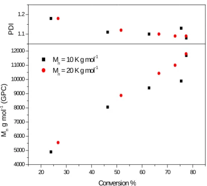
solution... 36 Figure 9 - Mnand PDI versus conversion for the co-polymerisation of C12/15
methacrylate andn-butyl methacylate. [C12/15
MA]:[n-BMA]:[Ligand]:[CuIBr]:[Intiator] - [51]:[42]:[2.1]:[1]:[1] (red), [25]:[21]:[2.1]:[1]:[1] (black) 90°C, 50% solids in toluene solution... 36
Figure 10 - Synthesis of a 3 arm initiator based on 1,3,5-benzenetriol using ratios
[triol]:[acid bromide]:[TEA] - [1]:[3.3]:[3.3] ... 37 Figure 11 - First order kinetic plot for the synthesis a 3 arm star C12/15 MA/n-butyl
methacrylate copolymer. [C12/15 MA]:[n-BMA]:[Ligand]:[CuIBr]:[Initiator] -[51]:[42]:[2.1]:[1]:[1] (red), [25]:[21]:[2.1]:[1]:[1] (black) 90°C, 50% solids intoluene
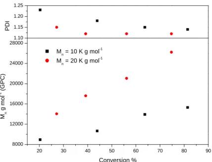
solution... 38 Figure 12 - Mnand PDI verus conversion for the co-polymerisation of C12/15
methacrylate andn-butyl methacylate. [C12/15
MA]:[n-BMA]:[Ligand]:[CuIBr]:[Intiator] - [51]:[42]:[2.1]:[1]:[1] (red), [25]:[21]:[2.1]:[1]:[1] (black) 90°C, 50% solids, toluene solution... 38
Figure 13 - Normalised GPC trace showing the difference between the two 3 arm star polymers made. It can be seen that there are no tailing effects to lower or higher
molecular weight... 39 Figure 14 - Synthesis of a four arm initiator based on pentaerytritol using the ratios –
Figure 15 - First order kinetic plot for the synthesis a 4 arm star C12/15 MA/n-butyl methacrylate copolymer. [C12/15 MA]:[n-BMA]:[Ligand]:[CuIBr]:[Initiator]
-[59]:[49]:[2.1]:[1]:[1] (red), [30]:[25]:[2.1]:[1]:[1] (black) 90°C, 50% solids in toluene
solution... 40
Figure 16 - Mnand PDI verus conversion for the co-polymerisation of C12/15
methacrylate andn-butyl methacylate. [C12/15
MA]:[n-BMA]:[Ligand]:[CuIBr]:[Initiator] - [59]:[49]:[2.1]:[1]:[1] (red), [30]:[25]:[2.1]:[1]:[1] (black) 90°C, 50% solids, in toluene solution... 40
Figure 17 - Normalised GPC trace showing the difference between the two 4 arm star polymers made. It can be seen that there are no tailing effects to lower or higher
molecular weight... 41
Figure 18 - Synthesis of a 5 arm initiator based on glucose in a 50:50 (v:v) mixture of pyridine and solvent using the ratios – [glucose]:[acid bromide] – [1]:[5.5]... 41
Figure 19 - First order kinetic plot for the synthesis a 5 arm star C12/15 MA/n-butyl methacrylate copolymer. [C12/15 MA]:[n-BMA]:[Ligand]:[CuIBr]:[Initiator]
-[51]:[42]:[2.1]:[1]:[1] (red), [25]:[21]:[2.1]:[1]:[1] (black) 90°C, 50% solids in toluene
solution... 42
Figure 20 - Mnand PDI verus conversion for the co-polymerisation of C12/15
methacrylate andn-butyl methacylate. [C12/15
MA]:[n-BMA]:[Ligand]:[CuIBr]:[Initiator] - [51]:[42]:[2.1]:[1]:[1] (red), [25]:[21]:[2.1]:[1]:[1] (black) 90°C, 50% solids, in toluene solution... 42
Figure 21 - Normalised GPC trace showing the difference between the two 5 arm star polymers made. It can be seen that there are no tailing effects to lower or higher
molecular weight... 43
Figure 22 Synthesis of an eight arm initiator based on lactose using ratios
-[lactose]:[acid bromide] - [1]:[8.8] ... 43
Figure 23 - First order kinetic plot for the synthesis a 8 arm star C12/15 MA/n-butyl methacrylate copolymer. [C12/15 MA]:[n-BMA]:[Ligand]:[CuIBr]:[Initiator]
-[51]:[42]:[2.1]:[1]:[1] (red), [25]:[21]:[2.1]:[1]:[1] (black) 90°C, 50% solids. ... 44
Figure 24 - Mnand PDI verus conversion for the co-polymerisation of C12/15
methacrylate andn-butyl methacylate to form an 8 arm star polymer. [C12/15 MA]:[n-BMA]:[Ligand]:[CuIBr]:[Initiator] - [51]:[42]:[2.1]:[1]:[1] (red), [25]:[21]:[2.1]:[1]:[1] (black) 90°C, 50% solids. ... 45
Figure 25 - Normalised GPC trace showing the difference between the two 8 arm star
polymers made. It can be seen that there are no tailing effects to lower or higher
List of Tables
Table 1 - Polymers synthesised to compare the effect of molecular weight and arm number on preformance as a VM... 32
1
Introduction
1.1
Core First stars by copper(I) mediated living radical polymerisation
(ATRP)
After the publication of the independent discovery of ATRP by Sawamoto1 and Matyjaszewski2 in 1995, a range of possible monomers and architectures was investigated by a number of groups across the world. Among this work, both Sawamoto
and Matyjaszewski investigated multi-arm architectures. Similar structures had been previously synthesised by ionic polymerisation processes; which are not as tolerant to as wide a range of functional groups as living radical polymerisation and the initiators for
these ionic systems are not as easily synthesised. This led to the publication of a number of articles by Sawamoto3, 4 and Matyjaszewski5 in 1998 describing the use of multiple arm, core first stars synthesised by ATRP.
Following these first publications, a number of groups demonstrated the wide range of molecules that can be transformed into ATRP initiators and used for successful
polymerisation to form stars. They can be broken down into 4 broad categories; 1) halo-esters; 2) sulphonyl halides based; 3) (haloalkyl) benzenes; 4) miscellaneous.
1.2
Halo Ester Initiators
O O O O Br O Br O Br O O O O Br O Br O Br O O Br O O O O O O O Br O Br O Br O Br O Br O O O O O O O Br O Br O Br O Br O O O O O O Br O Br O Br O Br O O O O O Br O Br Br
In1 In2 In3
In4 In5
The first of these initiators to be used as cores for ATRP stars were In2 and In4,
reported by Matyjaszewski et al.6 In this work, they detailed the polymerisation of n-butyl acrylate or styrene using a Cu(I)Br di-nonyl bipyridine catalyst. The authors demonstrated how the polymerisations were of a living nature yielding well-defined
polymers. Soon after, Haddleton and coworkers published on the use of phenolic initiators.6 Of particular interest was the use ofIn1. Here the authors used Cu(I)Br in combination with N-(n-octyl)-2-pyridylmethanimine as catalyst for the polymerisation of methyl methacrylate and styrene. Using this initiator, they noted that while changing
the halide to chlorine (and the copper salt to Cu(I)Cl ) a drop in rate could be observed for the polymerisation of MMA. This drop could, however, not be observed when
styrene was used as monomer, indicating that further optimisation of the MMA polymerisation is possible. The PDIs of the resulting polymers were found to be slightly
broader for the chlorine initiator/catalyst system which may be of importance for certain applications. Also in 1999, Haddletonet al.published the use of glucose as a core for a five arm core first star polymer.7 This initiator,In3, was used to polymerise both MMA and styrene, using a Cu(I)Br/ N-(n-pentyl)-2-pyridylmethanimine catalyst system. The glucose-based 5 arm initiator was later used by the same group to polymerise
dimethylaminoethyl methacrylate (DMAEMA).8 The high amine content was incorporated to give the polymer high muco-adhesion and was used to adhere to the
outside of fish. DMAEMA polymers were also made usingIn1andIn5to demonstrate that a range of star polymers with different numbers of arms would all muco-adhere.8
In5was also used to synthesise polymers suitable for core-cross-linking to form reverse micelles. This work was by Lerourx and coworkers.9 They polymerised glycidyl methacrylate which was then hydrolyzed to give di-alcohol functional monomer units. These were then partially esterified with alkyl groups to give a hydrophobic nature to the
O O O O O O O O O O O Br O Br O Br O Br O Br O Br O Br O Br O O O OH OH HO OH OH OH OH S O O
Figure 2 –Core-cross linked star polymers synthesised fromIn5.
1.3
(Haloalkyl) benzene initiators
Br Br Br
Br
O Si OSi
O Si O Si Cl Cl Cl Cl P N P N P N O O O O O O Br Br Br Br Br Br
In6
In7
In8
Figure 3- Multi-arm organic and inorganic (Haloalkyl) benzenes initiators for ATRP.
In the range of initiators used by Matyjaszewski and coworkers in his original paper on core-first star polymers the synthesis of 4 and 6 arm stars based on In7 and In8,
high degrees of control and narrow molecular weight distributions. The authors furthermore suggest that these star polymers could find applications in areas such as
“surfactants, viscosity modification, or adhesives technologies”.9 Later, Wang et. al. synthesised four arm stars using In7 with MMA or styrene.11 Due to the non-trivial nature of the synthesis of the initiatorsIn7andIn8they have not become as widely used
asIn1-5.
Matyjaszewski and coworkers published on their range of initiators for star polymers, Hadjichristidis et al.12 published on the synthesis of four arm stars using the initiator
In6. They used a Cu(I)Br/bipy catalyst system to polymerise MMA, t-BuMA and styrene. The same initiator was later used by Wuet al.to synthesise polymers of styrene or MMA.13 These polymers were post-functionalised with C60to give optical-limiting
properties to the polymer. Optical limiters, as defined by the authors, are devices that
strongly attenuate optical beams at high intensities while exhibit higher transmittance at low intensities.13 They can be useful for protecting the human eye and optical sensors from intense laser beams. By attaching the C60 to the polymer the poor solubility and
processability of the C60is overcome.
1.4
Sulphonyl Chloride initiators
SO2Cl
ClO2S
NH2
SO2Cl SO2Cl
SO2Cl
ClO2S
R R
R R R R
SO2Cl
R=
O O
O SO2Cl 4
In9 In10
In11 In12
ClO2S
SO2Cl
SO2Cl
SO2Cl In13
Figure 4 -Multi-arm organic sulphonyl chloride based initiators for ATRP.
This type of initiator was first used to polymerise linear polymers of styrene by Percecet al.14in 1995. The use of this type of mono-functional initiator led to the development of the corresponding multi-functional initiators, shown in Figure 4. First published of these
were In9, 11 and 12 by Percec and co-workers.15 In their report, they detailed the polymerisation of MMA or BMA using a Cu2O/bipy catalyst system. Interestingly, the
of initiating systems. Soon after, the polymerisation of acrylonitrile, using a variety of catalyst systems, was detailed also by Percec and co-workers.15 This polymerisation was initially carried out with mono-functional initiators, but later also usingIn9. The use of this type of initiator culminated in their use to form dendritic stars by the process coined Irreversible TERminator Multifunctional INItiator (TERMINI). Here, a three arm star
based onIn9was polymerised after which the chloro-functional end group reacted with the terminating agent,16 Figure 5. The terminating agent can be made into a di-functional initiator for ATRP; meaning that each initial arm of the polymer now has a branching point and two further polymer chains growing from it. This process can be
repeated, leading to the introduction of multiple branching points in the chain, yielding a dendritric polymer.
TBDMSO S O
NEt2
S
O NEt2
TERMINI
Figure 5 –The terminating agent, used by Percecet al.,which can be transformed into a
di-functional initiator suitable for ATRP.16
The group of Robello also contributed to the development of multi-functional sulphonyl chloride initiators for ATRP. They demonstrated how a simple benzene moiety could be
transformed into either a 5 or a 6 arm core suitable for use as an ATRP initiator,17such asIn10and13. A range of monomers were polymerised from these initiators including
MMA,t-BuMA, MA and styrene.
1.5
Shear Stability of Core First Stars
Some studies have been carried out as to the extent of shear stability depending on the
nature of the core of the star. This is the permanent breaking of the chemical bonds in the polymer either by mechanical or chemical processes; in this case mechanical. Two