|O|
DATASETS
|O
|
O
V
E
R
V
IE
W
|O
|
CO
MP
ON
EN
TS
|O
|
SE
T
T
IN
G
S
Interface redesign for the use of Microsoft PixelSense
in combination with peripheral VR-devices.
Tom Simons
October 2015
BSc graduation project
Industrial Design
Interface redesign for the use of Microsoft PixelSense in
combination with peripheral VR-devices.
Bachelor Industrial Design
Author: T.V. Simons S1116908
Study:
Industrial Design Universiteit Twente
Commissioned by: University of Twente Drienerlolaan 5
7500 AE Enschede, the Netherlands
Date Bachelor Exam: 29-10-2015
Examination committee: M.C. van der Voort R.G.J. Damgrave
Throughout my study Industrial Design, I came into contact with many aspects of the design process. Having done several programming related projects and subjects, I discovered that I found the design aspects relating to the digital domain the most appealing. While searching for an assignment for my Bachelor thesis, I encountered a description of a project to design an interface using haptic virtual reality interaction. Being fascinated by all the possibilities virtual reality offers, and the opportunity of working on a state-of-the-art piece of technology, I applied for an interview.
During the project I had to overcome many obstacles and got a taste of integrating the many aspects of the design process into one product. I feel that I greatly improved my skills, and I am happy to have not only designed a conceptual product, but also to have actually got to create a working prototype.
I would like to thank my supervisor, Roy
Damgrave, for all the support and feedback, and all my friends who helped me perform usage tests during several stages of this project.
In the current day and age the virtual world is becoming more and more a part of our daily routine. Whether you stay in touch with your friends through your smartphone, or watch a video on your laptop, we are surrounded by the virtual world.
In the past few years, significant steps have been made to blur the lines between the real world and the virtual world. Devices like the Oculus Rift allow people to be completely immersed in the virtual world, and that’s just the beginning.
The University of Twente’s goal is to stay ahead in these technical developments and has commissioned this assignment to make steps in the field of VR. The goal of this assignment was to create a system that allows users to use real world objects in unison with a virtual representation of this object. In the virtual world the objects can be augmented with additional information.
The design process started with making an analysis of the equipment and current system, and the needs of the different stakeholders.
Several scenarios were written to further understand the stakeholders. The analysis phase concluded with the formulation of the requirements for the system.
Once the requirements were clear, the design of the system could begin. Possibilities for several peripheral devices to work in the system were explored, the user interface was designed, and a technical design was made.
Once the final concept was chosen, the
realisation of this concept could begin. This was done in Unity1, with some additional coding in
Visual Studio2. The classes of the system were
designed in such a way that easy expansion of the system is possible. During this phase several technical limitations were encountered, due to which slight changes in the concept had to be made.
Finally, the created system was evaluated and several possible improvements were formulated. These improvements were the result of both
1 Game engine and programming environment: https://unity3d.com/
2 Programming environment: https://www.visualstudio.com/
a usage test and technical limitations which prevented implementation during the realisation phase.
Preface 4
Summary 5
Chapter 1: Introduction
10
1.1 - University of Twente
10
1.2 - Problem definition
10
1.3 - Aim of the project
10
1.4 - Reading guide
10
Chapter 2: Analysis
12
2.1 - System analysis
12
2.1.1 - Current system 12 2.1.2 - Use of the current system 12 2.1.3 - Shortcomings 13 2.1.4 - Technical details 13 2.1.5 - Stakeholder analysis 13
2.2 - Market research
14
2.3 - Scenarios
14
2.3.1 - Scenario 1: Design team 1 14 2.3.2 - Scenario 2: Design team 2 14
2.3.3 - Scenario 3: Customers 15 2.3.4 - Scenario 4: Promotion 15
2.4 - Platform
15
2.5 - Collage
16
2.6 - Requirements
16
2.6.1 - Use 16
2.6.2 - Look and feel 16 2.6.3 - Features 16 2.6.4 - Wishes 16
Chapter 3: Concept design
18
3.1 - Idea generation
18
3.1.1 - Devices and features 18 3.1.2 - VR-Table user interface 19 3.1.3 - Screen User Interface 21
3.2 - Concept generation
21
3.2.1 - VR-Table user interface 22 3.2.2 - Screen user interface 23 3.2.3 - Technical structure design 23 3.2.4 - N2-chart 24
3.3 - Concept detailing
26
Chapter 4: Concept realisation
28
4.1. - Environment
28
4.2 - System overview
28
4.2.1 - OverlayApp 28 4.2.2 - TableApp 29
4.2.3 - PC app 29
4.2.4 - File synchronisation 30
4.3 - Class scheme
30
4.4 - TableApp
32
4.4.1 - Touchdata 32 4.4.2 - SceneControl 32 4.4.3 - InterfaceControl 33 4.4.4 - TableTouchButton 33 4.4.5 - FingerControl 33 4.4.6 - ButtonControl 33 4.4.7 - UIAnimator & ChangeRightBorderImage 34 4.4.8 - TextFieldControl 34 4.4.9 - BrowserButton 34 4.4.10 - Browser 34 4.4.11 - BrowserColumn 34 4.4.12 - BrowserFolderButton 34 4.4.13 - BrowserFileButton 34
4.4.14 - ImportFiles & CancelImport 35 4.4.15 - CloseTear 35 4.4.16 - SUIControl 35 4.4.17 - MoveSUI & CloseSUI 35 4.4.18 - Quitbutton 35
4.5 - PCApp
35
4.5.1 - SceneControl 35 4.5.2 - InterfaceControl 35 4.5.3 - RoomCamera 36 4.5.4 - ThirdPersonCamera & Helper 36 4.5.5 - FollowMainModel 36 4.5.6 - UIScript 36 4.5.7 - UIMenuScripts 36 4.5.8 - SubButtonControl 36 4.5.9 - MainModelButton 36 4.5.10 - InputFieldInput 36
4.6 - Final system
37
4.6.1 - Setup 37
4.6.2 - Getting started 37 4.6.3 - Tag usage 37
Chapter 5: System evaluation
40
5.1 - Usage test
40
5.2 - Requirements
40
5.2.1 - Use 40
5.2.2 - Look and feel 40 5.2.3 - Features 41 5.2.4 - Wishes 41
5.3 - Recommendations
41
5.3.1 - One TableApp 41 5.3.2 - Central file database 41 5.3.3 - Refresh when file is changed 42 5.3.4 - Enhancing Collada import 42 5.3.5 - Embedded info in 3D-file 42 5.3.6 - Overwriting files on import 42 5.3.7 - Integrating devices 42 5.3.8 - Standalone models 42 5.3.9 - Overlapping interfaces 42 5.3.10 - Environment loading 42 5.3.11 - Room camera settings 43 5.3.12 - Improving the browser 43
5.4 - Possible expansions
43
5.4.1 - Other Peripheral devices 43 5.4.2 - Oculus rift 43 5.4.3 - Motion Controller 43 5.4.4 - Tagged objects 43
References 44
Appendix A
46
A.1 - Intuiface project
46
A.2 - Usage test 1
46
A.2.1 - Test Subject 1 46 A.2.2 - Test Subject 2 47 A.2.3 - Test Subject 3 48
Appendix B
50
B.1 - OverlayApp
50
B.2 - TableApp
50
B.3 - PCApp
50
Appendix C
52
C.1 - Usage test 2
52
1.1 - University of Twente
This project was commissisoned by the
University of Twente. The goals of the University of Twente are to promote innovation and entrepreneurship. Besides this the University of Twente is active in areas of social development. Because of this, the University of Twente strives to stay ahead in the field of technical development. This project was commissioned to contribute to this vision.
1.2 - Problem definition
The University of Twente has a research laboratory solely dedicated to research in the areas of virtual reality (VR). This laboratory has state-of-the-art equipment in this field, such as tactile pens that allow users to ‘feel’ their virtual 3D-model, Oculus Rifts to immerse users in the virtual world, and a Samsung SUR-40 with Microsoft Pixelsense1. This is a ‘VR-table’ that is
1 See: http://www.microsoft.com/en-us/pixelsense/default.aspx
able to form a link between the real world and the virtual world. By placing real world objects on the table’s surface, infrared cameras beneath the screen’s surface capture these objects, which in turn allows the VR-Table to ‘recognise’ them. This device has great potential for creating a close link between the real world and the virtual world. The University of Twente has a prototype of a system for this purpose, but this prototype works on a minimal level, requiring a great deal of expertise to operate, and low flexibility.
The problem addressed in this project was the redesign of this system, in order to utilize it to its full potential. This interface should be able to be used with minimal effort and expertise. It is intended to allow design teams to separate information of their design based on their field of expertise, while maintaining the VR-table as central hub. This way design teams can efficiently communicate with each other, whilst not being overloaded with information that is not relevant for the individual members’ field of expertise.
1.3 - Aim of the project
The final goal of the project is de redesign the existing user interface consisting of the VR-table and other peripheral devices. The final design should be realized. The final product should be a useful interface and provide users with a pleasant experience. Besides this, the system should be integrated with the University of Twente’s existing workflow, and the look and feel of the interface should integrate with the University’s vision.
1.4 - Reading guide
In this report, several terms will be used. The final product, including everything that is required to make it work will be referred to as ‘the system’. The term ‘VR-table’ will refer to the Samsung SUR-40 with Microsoft Pixelsense. ‘Peripheral devices’ will refer to all potential electronic devices to be used in the system.
In the upcoming four chapters, the design process will be explained in detail, starting with the chapter ‘Analysis’. In this chapter a basis is created for further design choices.
The chapter ‘Concept design’, several
possibilities for the system will be explored. At the end of this chapter a user interface and the technical structure of the system will be chosen.
In the chapter ‘Concept realisation’ the steps towards realizing the final system will be explained. This chapter also includes a description of the function of all of the classes in the final applications.
2.1 - System analysis
In order to gain an understanding of the goal and the possibilities of the system, an analysis was performed on the current system. This included the setup of the current system, the technical details and a stakeholders analysis to identify all the parties which come in contact with the system.
2.1.1 - Current system
The current system is centred around a ‘VR-table’. This is a Samsung SUR40 with Microsoft PixelSense table (formerly Microsoft Surface). The table is an interactive multi-touch
computer which can recognize certain real world objects. These objects can be a finger, a special ‘tag’ that works similar to a barcode, or an unrecognizable ‘blob’. Another key feature of the VR-table is that the orientation of these
objects can also be recognised, allowing for a full 360-degree experience around the table. For a promotional thesis, Thalen (2013) coded an interface to use the VR-table in combination with one or more computer screens as a design tool for User Centered design. The created interface responded to moving around physical objects on the table, each with a specific tag, which would then move around in a 3D-environment on the computer screen. This environment was created in Blender1 and
included the possibility to display a realistic environment with real time shadows and textures, but also the possibility for a more abstract, less detailed environment.
2.1.2 - Use of the current system
The VR-table and interface with a
3D-environment was used in a demonstration session by Thalen to show the possibilities of
1 3D-software: https://www.blender.org/
implementing virtual reality tools in the design process. This entailed that the interface was mainly set up to be a proof of concept and there was no elaborate user interface built for easy customisation by end users. The current
Chapter 2: Analysis
This chapter will explain the first phase of the design process, the analysis phase. During this phase, a basis is created on
which design choices will be based. The current system is analysed, market research is done and several scenarios are
created. The software platform is examined and finally requirements are formulated.
system displays a room where objects, such as furniture, can be placed by moving tagged cubes on the VR-Table. One cube is designated as the camera, and can be used to change the point of view in the room.
2.1.3 - Shortcomings
The current system is limited to the current setup, and was used primarily by Thalen as a proof of concept to trigger a discussion about the use of VR in the design process. Changing the setup requires expert knowledge of the used software, such as Blender, and is highly inflexible. The aim of this project is to design a new interface, which is able to implement this type of VR interaction in the design process and expand on the possibilities of the VR-table in combination with other peripheral devices as a design tool.
2.1.4 - Technical details
The current system is capable of recognising special byte-tags. The position, rotation and id of the tag are displayed on the VR-table surface and simultaneously stored in an SQL-database. Another computer reads the information in
this database and translates it to the position and rotation of a predefined 3D-model in the Blender environment. This Blender scene is then rendered on a separate screen.
2.1.5 - Stakeholder analysis
The main aim of the new system is to serve as a design tool for design teams during the design process. However, there are more stakeholders than just the specialists in these teams. These teams can be professional teams at companies, but also project teams consisting of university students. Because this is a new technology, companies need to be convinced this system is useful to purchase for their design department, and are thus considered as potential customers. Besides this the system can be used by the University of Twente as an advanced piece of engineering to convey their innovative vision towards potential students and guests.
Design teams
The design teams will be the main end users of the system. These teams consist of different specialists, each with their own field of
expertise. The design process usually requires
integration of different fields into one system, but not all information is relevant to each team member. One example is the design process of a USB-mouse. This product requires a designer of the ergonomics for the casing of the product, an electrical engineer for all the internal hardware, and a software engineer to make sure the product functions when plugged in. Each of the experts in the team is interested in the specifications of the product relating to their own field. The new system should therefore be able to separate the different sets of specifications, so each specialist will only see the information relevant to them.
Besides this the new system should add ease to the design process. It should provide a fast and intuitive interface between the designers and the computer, more so than with traditional design tools.
Potential customers
Potential customers in this context are
should be both functional and easily adjustable for multiple purposes.
Potential students
The new system should also be able to be used as a promotional tool towards potential students. The system should be able to be used in simple demonstrations by people without any technical background. The system should have an advanced look and feel, yet be simple and intuitive to operate.
2.2 - Market research
Although there are many applications which run on the VR-table itself, there aren’t many applications which use external devices as an extension of the VR-table. As the VR-Table is in essence a Windows PC, connecting external devices without any specialized software is limited to what a regular PC is able to do, and requires a physical cable to connect the two.
The VR-table uses Microsoft Pixelsense, which is an example of a Natural User Interface (NUI). A NUI removes the need for control devices and a Graphical User Interface (GUI) to control the computer’s actions. An NUI strives to provide
an intuitive control of the computer, as close as possible to real world object manipulation. The new system should make use of this capability, and thus the users should be able to know how the interface works without prior knowledge.
Other examples of Natural User Interfaces include Microsoft’s Kinect,2 Nindento Wii3, and
Elon Musk’s new gesture-controlled interface4.
2.3 - Scenarios
In order to further understand the needs of the stakeholders several scenarios were set up.
2.3.1 - Scenario 1: Design team 1
Tony is an electrical engineer in a design team working on a new type of USB-stick. The design team consists of three other members: An Industrial designer, a programmer and a marketing manager. The design team has to work on the following components: A casing, circuit board and software, packaging and marketing. Tony is only interested in the circuit
2 Motion controller: kinect.com
3 Gaming console: wii.com
4 See: http://www.dailymail.co.uk/sciencetech/article-2414005/
Hyperloop-creator-invents-Iron-Man-inspired-3D-software-design- ROCKET-PARTS.html
board and parts of the software. Their company has recently acquired a new design tool to help them work on this project. The tool allows for the entire team to work on the same computer model, but also to move (a part of the) the virtual model to other devices and separate its components into the team members’ specific area of expertise. The team members have never used the new design tool before. However, immediately after starting to use it, they know how to move the model around, and after 5 minutes they have figured out how to use the tool in their work. Tony places a mock-up of the USB-stick on the table and immediately a menu appears around the model, which allows the team to choose which part they want to see. Tony drags the tab labelled ‘electronics’ to the side of the table, which makes the entire circuit board appear on a separate screen. Tony analyses the circuit board while the rest of the team discusses something unrelated.
2.3.2 - Scenario 2: Design team 2
to the specifications, and once she is finished presents it to the rest of the team. However, the team members working on the exterior of the product have changed some details in different parts of the model, so Maria has to incorporate those changes to the model as well. Slightly agitated she returns to her computer to change the details, only to discover the changes affect the electronics as well. She contacts the electrical engineers of the team to explain the problem. Frustrated, she waits several days until the electrical engineers have devised a solution. She wishes there would be a more efficient way of communicating between the different disciplines in the team.
2.3.3 - Scenario 3: Customers
FruitBasket is a company specialized in consumer electronics. In order to maintain a competitive edge in their market segment, continuous innovation is required. All products the company produces are carefully designed by teams of specialists. To ensure reliable and efficient communication between the different team members, the company’s executive board is researching new design tools to enable their design teams to work fluently. The sought after tool has to remove the obstacles imposed by traditional design tools. Besides this, the new
tool has to be cost efficient and must not require training in order to use. The tool has to integrate with the companies established computer aided design (CAD) tools.
2.3.4 - Scenario 4: Promotion
James is an upcoming student. He is fascinated by new technology and wishes to become an ‘inventor’ when he graduates. During the open days of the University of Twente he is shown the university’s virtual reality lab. The lab has a futuristic feel to it and the university’s VR-system fits right in this environment. A demonstration is given where a physical 3D-model, which was printed only minutes ago in the previous stage of the tour, is placed on the table. James feels like he is in a science fiction film, as the table responds to the model, creating a digital version on a computer screen. The demonstrator swipes on the table and a fancy looking exploded view is produced on several screens around the VR-table. James is so impressed, he enrols the next day.
2.4 - Platform
The new system will be realised using the Unity engine. Unity is a development platform able
to create both 2D and 3D-applications, and is mostly used for games. It has native support for multiple platforms, such as Windows, Mac OSX and iOS. This multiplatform support allows for easy adaptation of the new software to be able to run on many devices.
Unity is able to natively read 3D-files with the .dae, .3ds, .dxf and .obj extension. These are the most used file formats and most 3D-applications are able to export in these formats. Other formats such as 3DS max, maya and blender files are able to be imported when a copy of the respective software is installed on the computer.
The University of Twente uses Solidworks as main 3D-CAD software. Solidworks is one of the industry standards regarding CAD. Unity is mostly considered a game engine and therefore optimised to be used with polygon-based models, whereas Solidworks creates feature-based models. Therefore, some compatibility problems may arise when trying to integrate the two. Although Solidworks is able to export in one of the four native formats Unity uses, any changes made to the CAD-model will require an additional export to be able to be read by Unity. If possible this step should be automated
Chapter 2
so that any changes in a CAD-model will be immediately reflected in the VR-system.
2.5 - Collage
To try to envision the mood the system would have to convey the following collage was made. The collage includes both real and fictional uses of VR.
The main thing seen in the collage is that all the people use their entire arms and hands to manipulate the virtual world. This is in line with the idea of a NUI, as real world manipulation
also requires physical movement. The collage also conveys a futuristic and complex feel. This contrasts with the simplicity a NUI tries to achieve. However this contrast will allow for a pleasant user experience as the user will feel in control of something complex, without having to go through rigorous training.
2.6 - Requirements
From the analysis above, the following requirements are formulated.
2.6.1 - Use
• The new system should be usable without programming knowledge.
• The new system should be able to
separately display information according to relevant field of expertise.
• The new interface should be intuitive to use. • Limited customisation should be required
of the users’ CAD-models in order to be usable with the system.
• The system should implement a natural user interface.
• The system should show simple information at first, but this information should expand
at the users’ will.
2.6.2 - Look and feel
• The new system should have a futuristic look.
• The system should make the user feel highly in control of the information and models. • The new system should achieve a complex
feel while maintaining an intuitive control.
2.6.3 - Features
• The new system should be able to connect with multiple devices.
• The new system should be easily expandable to accommodate for new technologies. • The new system has to be usable with
existing 3D-software and -files.
• The new system has to be programmed in Unity.
2.6.4 - Wishes
Besides these requirements some wishes were derived, to further the natural feel of the user experience.
• The new system should be able to
automatically link real world objects to their digital counterpart.
• The system should automate the CAD-file conversion to a Unity native file.
Chapter 2
3.1 - Idea generation
Once the analysis was completed, the design of the new system could begin. This began with the generation of ideas for many different aspects of the system. This included features of the system, the graphical design of the user interfaces, and technical structure.
3.1.1 - Devices and features
The VR-table is the main component in the new system, but there will be several other devices that will also be part of the new system. The first component that comes to mind is a monitor, possibly connected to a separate computer. This monitor will be the primary source of output for the system,
displaying a virtual version of the models and its environment.
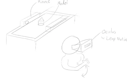
Besides this, head-mounted VR displays, such as the Oculus Rift, are on the rise. These displays
allow the user to see the virtual object in 3D-perspective and will therefore enhance the look and experience of the 3D-models and environment.
Displaying content on mobile devices is also a possibility. Mobile devices, such as smartphones and tablets, would allow a great deal of
flexibility. In case a tag is placed on the back of a mobile device, not only could this device then be used for the output, but it could also be used to generate input on the VR-table. A phone placed next to a model could enable it to copy the model view to the phone. The tagged phone could also act as a camera model, with the camera’s point of view displayed on the phone’s
Chapter 3: Concept design
In this chapter the design phase will be discussed. In the first part several ideas are proposed, which could be
incorporated in the system. In the second part of this chapter these ideas will be converged into a final concept.
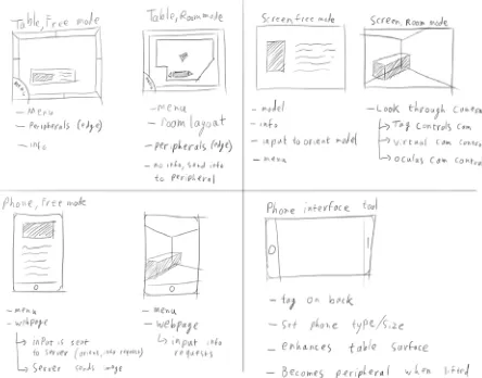
screen. Another way to use mobile devices could be in the form of a virtual loupe such as proposed by Weidlich, Cser, Polzin, Cristiano & Zickner. (2009). The user then uses the mobile device to control the model’s position orientation and zoom on the screen. This could be just on the mobile device itself, but also on a secondary screen. Several possible interface options are shown in image 3.2.
Aside from the VR-table itself and mobile
[image:19.842.316.531.339.471.2]devices, other input devices are also a possibility. The limitation of the interface between the table and the physical model is that the physical model needs to have a predetermined tag attached underneath it. It is not the model itself that is linked with the virtual model, but the tag on the model that is pre-programmed to correspond to a certain virtual 3D-model. If this process could be automated, it would take away another barrier and shift the system more towards a NUI. It would be possible to achieve this by using several 3D-scanners, such as Microsoft Kinects to scan the objects on the table, finding the corresponding model on the computer, and linking the tag to this
model. Kinects have native Unity support, which allows for easy integration with the rest of the software for the system. This is a possibility only because the system is intended to be used in conjunction with a 3D-representation of a virtual model and is of course limited to the resolution of the Kinects and obstruction of the model on the table by other models.
Using a Leap Motion1 sensor in conjunction
with an oculus rift would also enhance the
1 Motion controller: https://www.leapmotion.com/
NUI characteristics of the system. The Leap Motion is a sensor that allows users to see and use their hands in virtual reality. This way the control of the virtual models is no longer limited to traditional computer input, such as mouse and keyboards. Instead, users can control their virtual models directly with their hand gestures.
3.1.2 - VR-Table user interface
The VR-table is the centre of the system and the primary source of input. Because multiple models are intended to be placed on the VR-table’s surface, a compact user interface is required. This allows for more models being placed in each other’s proximity. Users should be able to easily expand and collapse the user interface, to show more information on a model, and make room for other interfaces, respectively. To keep the user interface simple and easy to learn and understand, adequate use of submenus should be made. By doing so users are not overwhelmed by a barrage of options, resulting in confusion. Having many submenus inherently requires some options to be hidden from plain sight. The interface should therefore
be intuitive to enable users to find all options they want without having to search through all the submenus. To create easy to understand
submenus, categorization is important. One category is the information, or data, that should be displayed. Because the nature of
this information differs per product, a further subdivision is hard to predetermine. Another set of information that can be associated with a single product are its components. Components differ from data in the sense that data is an abstract concept associated with the product, such as price, dimensions etc., while components are the physical components of a product, such as circuit board, casing, battery, etc. All these components can in turn have their own datasets associated with them.
Another important aspect of the interface is that it should be usable from any direction. As the intended use of the system is to have users stand on any side of the VR-table’s surface, there should be as little directional limited aspects to the interface. Finally, the interface should be able to be used with a variety of model shapes. The tagged object is part of the interface, but the user is the one determining the shape and size of the plain touching the table’s surface. This should be taken into account as much as possible with the interface’s design.
Besides providing information about the model, the user interface should also be integrated with other connected devices. The VR-Table acts as a central interface with the other devices as secondary interfaces, all these interfaces
Image 3.4: Scetches of the user interface design of a single model
should integrate to create one coherent system. This can be achieved by having a similar layout of the interface across all devices, but also by incorporating all connected devices in the table-interface. In image 3.6 some examples on how this could be implemented are shown.
3.1.3 - Screen User Interface
The second interface to be used is an interface on another screen. This screen can for example be a separate PC with a monitor or a mobile device. The function of these screens is primarily to provide a virtual environment with a virtual 3D-representation of the models and their
related information. When displaying the models, the user may want to choose one of two
distinct display methods.
Room Mode
The first display method requires the models to maintain the same spatial relation to each other. This method is useful when for example users have a floor plan of their room and wish to create several possible configurations of furnishing. The tagged objects are scale models of pieces of furniture, and their position in relation to each other and on the table matters for the room decor. One of the tagged objects is used to place a camera in the room, as to simulate a person’s point of view in the room. The secondary screen then displays a virtual representation of the furnished room from this point of view.
Free mode
The second possibility is to allow users to examine one model up close. This is useful when wanting to examine a detail of a specific model. In this case the camera is not linked to a model on the table, but is controlled by the user on the secondary screen. In this case the spatial relation between the tagged objects on the table is less important.
[image:21.842.65.287.205.379.2]These two viewing modes not only affect the way the interface on the peripheral device behaves, bus possibly also the layout of the table. In room mode an outline of a floor plan can be added to the table’s surface to show the user the bounds of the room. These walls should then also be reflected in the virtual representation of the room on the peripheral devices.
3.2 - Concept generation
With these ideas as a basis, a conceptual system was created. The final system should be able to be expanded with extra functionality easily. Because of this, the choice was made to create a modular concept, instead of several predefined concepts. This means several concepts of
different modules were made which integrate to one final system. For this project a difference was made between the essential modules to create the basis for a functional system and extensions, which improve the system. The essential modules are the VR-Table and at least one secondary screen.
Chapter 3
Concept design
3.2.1 - VR-Table user interface
The first module was the user interface of the table. From the sketches created for this interface, three interface concepts were created (images 3.7 3.8 & 3.9). In order to create a basis for a choice for one of these concepts, a simple prototype of the interface was created
in Intuiface2. Intuiface is a program that allows
for the creation of simple user interfaces for several platforms, most notably the VR-Table. The Intuiface file and the questions and answers for this usage test can be found in appendix A. One key feature omitted from the usage test was the possibility to send a selected model or information to a peripheral device. This choice was made because of technical limitations. The final concept should include a way to send selected information to a user specified screen, for example by dragging this to an icon at the side of the table. The test subjects mostly showed a preference for the second interface, but also the third interface gathered positive reactions.
After this test the choice was made to use the second interface. This was for two reasons: firstly because most test subjects preferred this interface, and secondly because the third interface takes up quite some space next to the tagged object. As stated earlier, the interface should be as compact as possible. Some improvements were made to the interface design after the usage test, such as inverting the text. This was done because the tagged object obscures the top menu, which was the only
2 Simple interface creation software: http://www.intuilab.com/
Image 3.7: VR-table interface concept 1
Image 3.8: VR-table interface concept 2
Image 3.9: VR-table interface concept 3 Model name Overview i Overview Model name Title
Lorem ipsum dolor sit amet, consectetur adipiscing elit, sed do eiusmod tempor incididunt ut labore et dolore magna aliqua. Ut enim ad minim veniam, quis nostrud exer-citation ullamco laboris nisi ut aliquip ex ea commo-do consequat. Duis aute irure commo-dolor in reprehen-derit in voluptate velit esse cillum dolore eu 1. Overview
2. Visitors 3. Costs 4. Services 5. Settings
Model name Model name
Visitors Costs Dimensions About References Model name Visitors Costs Dimensions About References Title
Lorem ipsum dolor sit amet, consectetur adipiscing elit, sed do eiusmod tempor incididunt ut labore et dolore magna aliqua. Ut enim ad minim veniam, quis nostrud exercitation ullamco laboris nisi ut aliquip ex ea com-modo consequat. Duis aute irure dolor in reprehenderit in voluptate velit esse cillum dolore eu fugiat nulla pari-atur. Excepteur sint occaecat cupidatat non proident, sunt in culpa qui officia deserunt mollit anim id est laborum. Components O verv iew D ata set s S et tings Title
Lorem ipsum dolor sit amet, consectetur ad-ipiscing elit, sed do eiusmod tempor incididunt ut labore et dolore magna aliqua. Ut enim ad minim veniam, quis nostrud exercitation ullamco laboris nisi ut aliquip ex ea commodo conse-quat. Duis aute irure dolor in reprehenderit in voluptate velit esse cillum dolore eu fugiat
menu with the text right side up. The colours were changed to give the interface a more futuristic look. The final interface concept can be found in image 3.10.
3.2.2 - Screen user interface
The user interface for the secondary screen was the second module. This interface should display the virtual version of the tagged objects and its information. A usage test was not performed for this interface, because creating a functional prototype would require much time. As this interface should integrate with the interface of the VR-table, the same category division was made. The settings menu was added fields to set the 3D-model’s import values, as the scale or orientation may differ per 3D-application. The two display methods explained earlier were included in this interface, allowing the user to enable or disable “Room
mode” under settings. When not in room mode, the user gains control over the camera. The main features of this camera control are to orbit and pan by clicking and dragging and to zoom by scrolling. Different 3D-Applications require a different mouse button to be pressed, possibly in conjunction with a modifier key on the keyboard. For this concept mouse-only control was chosen, to allow users to control the camera with one hand and minimal effort. Left clicking and dragging orbits the camera, and right clicking and dragging pans the camera.
Users should also be able to select of which model they want to see extra information. Especially in free mode, the model the user wants to switch to may not be in view. Simply clicking on the model mesh is therefore not always an option. To make all models equally accessible, the user can select the model they wish to focus on from a dropdown menu.
3.2.3 - Technical structure design
To be able to realize the conceptual system, a technical design had to be made. One of the first technical challenges faced, was the exchange of information to the different devices. Having all devices be directly connected to the VR-Table highly limits the amount of devices
Chapter 3
Concept design
Image 3.10: The chosen user interface. Top: closed user interface. Bottom: open user interface.
DATASETS OV ER V IE W CO MP ON EN TS SE T T IN G S DATASETS OV ER V IE W CO MP ON EN TS SE T T IN G S
Title of the submenu
Lorem ipsum dolor sit amet, consectetur adipiscing elit, sed do eiusmod tempor incididunt ut labore et dolore magna aliqua. Ut enim ad minim veniam, quis nostrud exercitation
ullamco laboris nisi ut aliquip ex ea commodo consequat. Duis aute irure dolor in reprehenderit in voluptate velit esse cillum dolore eu fugiat nulla pariatur. Excepteur sint occaecat cupida-tat non proident, sunt in culpa qui officia deserunt mollit anim id est laborum. Sed ut perspiciatis unde omnis iste natus error sit voluptatem accusantium doloremque laudantium, totam rem aperiam, eaque ipsa quae ab illo inventore
Title
Lorem ipsum dolor sit amet, consectetur adipiscing elit, sed do eiusmod tempor incididunt ut labore et dolore magna aliqua. Ut enim ad minim veniam, quis nostrud exercitation ullamco laboris nisi ut aliquip ex ea com-modo consequat. Duis aute irure dolor in reprehenderit in voluptate velit esse cillum dolore eu fugiat nulla pariatur. Excepteur sint occaecat cupidatat non proident, sunt in culpa qui officia deserunt mollit anim id est laborum. Sed ut perspiciatis unde omnis iste natus error sit voluptatem accusantium doloremque laudantium, totam rem aperiam, eaque ipsa quae ab illo inven-tore veritatis et quasi architecto beatae vitae dicta sunt explicabo. Nemo enim ipsam voluptatem quia voluptas sit aspernatur aut odit aut fugit, sed quia consequuntur magni dolores eos qui ratione voluptatem sequi nesci-unt. Neque porro quisquam est, qui dolorem ipsum quia dolor sit amet, consectetur, adipisci velit, sed quia non numquam eius modi tempora
inci-Image 3.11: Final device-UI concept
Main model Select model
that can be connected to the system. Besides this, a physical cable is required to connect to the VR-Table’s computer, which also limits the range of the system. On the flipside, if the secondary monitor would be connected to the VR-Table itself, it would have direct access to the files on the table, and thus the table could act as a central file location. However, this advantage is minimal when taking into account the modern day Internet speeds. Incorporating external devices, which are not directly
connected to the VR-Table, would require the user inputted files to be synchronized to all devices, or to be downloaded from a central location. The best option would be to have a central server to manage all the users files and settings. Devices in the system could then download these files to use in their respective app. Position and rotation data of the tagged objects on the table can be stored in a database on this server as well.
In some cases it would be preferable not to have a standalone application on a device. When giving a demonstration for a group of guests for example, it would be preferable if all the guests could follow the demonstration on their own smartphone or tablet, without having to download a dedicated app for this purpose.
In this case a webpage would be the ideal solution. The webserver would then have all the necessary files to provide output on the mobile screen, and the client phone would only have to process the users touch input. Because this kind of webpage is not essential to the minimal system, it is considered an extension module.
3.2.4 - N
2-chart
Chapter 3
Concept design
Image 3.13: N2-chart Room mode
N2-chart Room mode
User Touch
Tagged objects
Info request Camera settings
Info request Camera settings
Info request Camera settings
Visual
feedback VR-table PositionRotation Tag id / finger
Model info Connected devices
Server Position
Rotation Model info
Position Rotation Model info
Image
Visual feedback
Device id PC
Visual feedback
Device id Mobile App
Visual feedback
3.3 - Concept detailing
Before the realisation phase could begin, some detailing was done to improve the interface concepts. The VR-table-interface has some minor change in the colour of some buttons to improve the contrast. The Buttons also have an icon added to further differentiate them from each other. These icons are the same ones used in the interface on the peripheral screens. One major feature added to the VR-table’s interface is the ability to duplicate a tag’s interface by ‘tearing’ it from the tagged object. The user can then rotate this standalone version of the interface to make it readable for a user on the other side of the table. This was added to increase the omnidirectional possibilities of the VR-table. Finally, a simple graphic was made to add the possibility of having a tagged object act as the camera in the scene.
Image 3.14: N2-chart Free mode
N2-chart Free mode
User Touch
Tagged objects
Orientation Pan
Zoom Info request
Orientation Pan
Zoom Info request
Orientation Pan
Zoom Info request
Visual
feedback VR-table
Position Rotation Tag id / finger
Model info Connected devices
Server Position
Rotation Model info
Position Rotation Model info
Image
Visual feedback
Device id PC
Visual
feedback Device id Mobile App
Visual
Chapter 3
Concept design
|O| DATASETS
|O| OV E R V IE W |O | CO MP ON EN TS |O | SE T T IN GS
Lorem ipsum dolor sit amet, consectetur adipiscing elit, sed do eiusmod tempor incididunt ut labore et dolore magna aliqua. Ut enim ad minim veniam, quis nostrud exercitation ullamco laboris nisi ut aliquip ex ea commodo consequat. Duis aute irure dolor in reprehenderit in voluptate velit esse cillum dolore eu fugiat nulla pariatur. Excepteur sint occaecat cupidatat non proident, sunt in culpa qui officia deserunt mollit anim id est laborum. Sed ut perspiciatis unde omnis iste natus error sit voluptatem accusantium doloremque laudantium, totam rem aperiam, eaque ipsa quae ab illo inventore veritatis et quasi architecto beatae vitae dicta sunt explicabo.
|O| DATASETS |O| OV E R V IE W |O | CO MP ON EN TS |O | SE T T IN G S
|O| DATASETS |O| OV E R V IE W |O | CO MP ON EN TS |O | SE T T IN G S
Title of the submenu
Lorem ipsum dolor sit amet, consectetur adipiscing elit, sed do eiusmod tempor incididunt ut labore et dolore magna
aliqua. Ut enim ad minim veniam, quis nostrud exercitation ullamco laboris nisi ut aliquip ex ea commodo consequat. Duis aute irure dolor in reprehenderit in voluptate velit esse cillum dolore eu fugiat nulla pariatur. Excepteur sint occaecat cupidatat non proident, sunt in culpa qui officia deserunt mollit anim id est laborum. Sed ut perspiciatis unde omnis iste natus error sit voluptatem accusantium doloremque laudantium, totam rem aperiam, eaque ipsa quae ab illo
Image 3.15: The final interface designs
Title
Lorem ipsum dolor sit amet, consectetur adipiscing elit, sed do eiusmod tempor incididunt ut labore et dolore magna aliqua. Ut enim ad minim veniam, quis nostrud exercitation ullamco laboris nisi ut aliquip ex ea com-modo consequat. Duis aute irure dolor in reprehenderit in voluptate velit esse cillum dolore eu fugiat nulla pariatur. Excepteur sint occaecat cupidatat non proident, sunt in culpa qui officia deserunt mollit anim id est laborum. Sed ut perspiciatis unde omnis iste natus error sit voluptatem accusantium doloremque laudantium, totam rem aperiam, eaque ipsa quae ab illo inven-tore veritatis et quasi architecto beatae vitae dicta sunt explicabo. Nemo enim ipsam voluptatem quia voluptas sit aspernatur aut odit aut fugit, sed quia consequuntur magni dolores eos qui ratione voluptatem sequi nesci-unt. Neque porro quisquam est, qui dolorem ipsum quia dolor sit amet, consectetur, adipisci velit, sed quia non numquam eius modi tempora
inci-Main model Select model
4.1. - Environment
Most of the final system was created in Unity. The original intention was to create everything in this environment, however this was not possible due to a limitation in Unity. Unity (verson 5.1.1 at the time of writing) works in .NET framework 2.0, while the drivers used to get input from the VR-table’s infrared cameras are compiled in .NET 4.0. This means that Unity is unable to compile programs that can directly control the VR-table’s infrared cameras.
Instead of looking for another environment to program in, a workaround was found to deal with this shortcoming (see 4.2.1 for a technical explanation). This choice was made for two reasons: firstly, Unity is a widely used and comprehensible program, so switching environment would limit the expansion possibilities beyond this project. Secondly, Unity, being a game engine, has a lot of standard
functionality to create graphical user interfaces, handle 3D models, virtual cameras, lighting etc. Using a standard programming environment would require that these features be created manually.
4.2 - System overview
The final product consists of three computer programs, an SQL database and a third party file-synchronisation tool. Two of the three programs work in unison on the VR-table to gather user input on the VR-table and provide a graphical user interface. The third program is a standalone executable on other Windows PCs to provide a virtual-reality environment for the models and information. All programs are connected to the SQL database, which stores a unique id, the position and rotation of the input object placed on the VR-table, and whether this input device is a finger, tag or an unrecognisable
‘blob’. In case a tag is recognised, the tag id is stored in the database. The possibility to send models or info to devices, directly from the table, and vice versa has been removed. This choice was made because it was technically too difficult to realize. All applications, as well as their source code and project files can be found in appendix B.
4.2.1 - OverlayApp
The functionality of the VR-table consists of two applications working in unison with each other. The first application is a transparent application (OverlayApp), which was created in Visual Studio. Visual studio is a programming environment capable of creating programs for the .NET 4.0 framework. This application is layered on top of the second application (TableApp) and drives the infrared cameras of the VR-table to capture user input. The raw input is processed to determine the type of object placed on the table (tag, finger or blob)
Chapter 4: Concept realisation
and the position and rotation of the object. This data is then sent to be stored in an SQL-database. Once an object is removed from the table, the corresponding entry is removed from the database. This way the database contains real-time data of all possible information of every object on the table. When this application is loaded, it truncates the database, and removes any entries that may have been there from before. This application was adapted from a demo application supplied by Microsoft for the VR-table1. Image 4.1 displays a screenshot of
the application before modification. All possible
1 Found in the Surface SDK 2.0: https://www.microsoft.com/en-us/
download/details.aspx?displaylang=en&id=26716
info of an object on the table is also displayed. After modification, all graphical elements were removed.
4.2.2 - TableApp
The second application on the table (TableApp) is created in Unity and provides the graphical user interface on the VR-table. This application runs underneath the input application. Because the OverlayApp runs on top of this application, the TableApp has no direct access to input devices, such as the keyboard or mouse,
however due to the intended touch surface, this
was not needed anyway.
The TableApp continuously reads all the entries from the database and uses these entries to determine what the user has input. For all read tags, the app will create interfaces related to these tags. Reading the position data of finger entries and calculating the difference from the previous frame simulates touch input. The Table app can load and read text files to provide extra information for the tag placed on its surface. Image 4.2 shows the final system running on the VR-table.
4.2.3 - PC app
The third application (PCApp) works as a standalone program on on one or more
separate PCs. This application visualises a virtual reality version of the objects on the table using Collada 3D-files2. The PCApp is also connected
to the database, and uses its entries to position the 3D-objects at the same position in the virtual world as in the real world. This app is also able to load the additional information provided with each model.
As stated earlier, Unity normally natively
2 See: https://www.khronos.org/collada/
Image 4.1: Microsoft’s demo application
supports a variety of 3D-file formats. However when programming the import of external 3D-models a problem was encountered. Unity is not able to load external recourses at runtime, and when compiling the standalone application all resources in the Unity project are compiled with this application. Because of this, the PCApp would be unable to allow the user to load a model at runtime. This problem was solved by using a third party plugin that can load Collada files at runtime3. However, the drawback of
using this plugin was that it was only able to load the mesh from the file, and not the materials and textures.
4.2.4 - File synchronisation
In order to synchronize the loaded text and model files, the third party application BitTorrent Sync4 was used. The TableApp also
acts as the database for all text and model files, and by syncing the folder containing these files to a PC, the PCApp has access to the same files as the TableApp.
3 SimpleCollada: https://www.assetstore.unity3d.com/en/#!/
content/19579
4 File Synchronization tool: https://www.getsync.com/
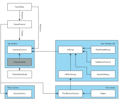
4.3 - Class scheme
In the following paragraphs the technical setup of the code will be explained. Because the OverlayApp is a slightly modified and stripped version of a demo application supplied by Microsoft, and the code to write entries to the database is very similar to the code to read entries from the database, this application will not be described in depth. The exact code and Unity projects can be found in appendix B of this report.
SQL-database
OverlayApp TableApp
PCApp File sync
User input User input
Chapter 4
Concept realisation
TouchData
SceneControl
Cr
eates
Pr
esent in
Pr
esent in
QuitButton
InterfaceControl
UIAnimator
ChangeRightBorderImage
CloseTear TextFieldControl*
ButtonControl** Browser
BrowserButton
BrowserColumn
ImportFiles BrowserFolderButton
BrowserFileButton
CancelImport TableTouchButton
Tag interface
SUIControl
CloseSUI TextFieldControl*
ButtonControl**
Standalone Interface
MoveSUI FingerControl
Finger Interface
* / **: The same classes, but displayed twice to give a complete overview of the two interface objects. TableTouchButton class: all classes in this square are extensions of this class
Unity prefab objects containing GameObjects which have containing classes attatched
Cr
4.4 - TableApp
First the classes of the TableApp will be
discussed. Because the OverlayApp was created out of necessity, minimal functionality was added. The TableApp processes all input data and creates output for the user.
4.4.1 - Touchdata
[image:32.842.59.465.91.443.2]An instance of the TouchData class stores the information associated with one entry from the database. This class has some minor methods such as one to check whether or not the entry is a tag and one to transform the position in table space to a position in Unity’s camera space.
4.4.2 - SceneControl
The Scenecontrol class handles connecting to and reading the database, and creating the appropriate objects associated with the database entries. It also starts an instance of the OverlayApp so users won’t have to do this themselves. There are two lists maintained by this class: one that contains the raw entries from the database, and one that contains all objects associated with the database entries. By comparing these, the application is able
TouchData
SceneControl
Cr
eates
Pr
esent in
Pr
esent in
InterfaceControl
SimpleCollada
Tag interface
MainModelButton
SubButtonControl UIScript
InputFieldInput
User Interface (UI)
UIMenuScript
Imported class, no changes made. Added for clearer overview.
Unity prefab objects containing GameObjects which have containing classes attatched
Free camera
RoomCamera
Room Camera
FollowMainModel
to determine if an object has been added or removed from the VR-table’s surface. When the app is closed the database is truncated.
The database is cleared at two times: when the application is started and when the application is exited. The first is done as to ensure the input app starts without residual entries from a last session, or manually inserted into the database between sessions. If clearing on exiting the app would not be done, and there would be an entry at the position of the close button of the application, the application would close immediately after being opened a second time.
4.4.3 - InterfaceControl
For every entry that is read by the
SceneControl a premade TagInterface-object is loaded. There are three different types of interface-objects: one for tags, one for the tag that is assigned as the camera, and one for fingers. This object contains images, buttons, text fields and other components necessary to make the interface function. At the top of this hierarchy is the InterfaceControl. This class contains an instance of the TouchData class, where, among others, its position, rotation and tag id are stored. Upon initialization, it creates the folder structure on the hard drive for this tag where the info and model files
will be held. Some code was added to create the functionality to automatically rotate the interfaces when they overlap each other. In the end this was too difficult to realize in a reliable manner, and thus this functionality was removed.
4.4.4 - TableTouchButton
Because the table app doesn’t use Unity’s default input functionality, but derives input from the database entries, Unity’s default touch input modules could not be used. Instead, the TableTouchButton class was created as a base class to handle touch input. All classes that require handling touch input extend from this class.
Because it is a base class, it only has methods that are called when the user taps on the table, drags on the table or a drag on the table ends. In child classes these methods can be overridden to add functionality specific to each button. Although this class acts as an event handler for the fingers, the class FingerControl handles the triggering of these events. Upon the creation of an instance of the FingerControl class, it checks if its position is inside the bounds of any of the TableTouchButtons present. If it is, it will trigger the TableTouchButton to track the fingers position. If the position stays within a certain value and is then removed, this will
trigger a Tap event. If the position exceeds this value, a Drag event is triggered. Classes of the TableApp that are extensions of this class will be referred to as buttons.
4.4.5 - FingerControl
Entries with their tag id set to “Finger” will trigger the creation of a FingerInterface-object. This object has the InterfaceControl component attached to regulate its position and rotation, and it also has the FingerControl class attached. One of the functions of this class is to calculate the difference in position and rotation from the previous frame, in order to determine the amount of movement of the finger. Besides this it is the event trigger for the TableTouchButtons. When this class is initialized, it will check whether it is in bounds of any TableTouchButton. If it is, it will trigger the affected TableTouchButton to handle the finger’s input action.
4.4.6 - ButtonControl
This one class primarily controls the four buttons on the outside of the interface. This class is an extension of the TableTouchButton class, and by overriding the OnDrag and OnTap methods, the four buttons were made responsive to touch input by the user. By
Chapter 4
dragging, the four buttons rotate around the centre, making them easily accessible for the user. By tapping, the class first checks which of the four buttons is pressed, and then processes the appropriate action.
Besides these four buttons, it also handles the buttons of the submenus for components and datasets. This is because these buttons behave in a similar fashion to the overview button, by calling the TextfieldControl to read and display the corresponding text file.
4.4.7 - UIAnimator &
ChangeRightBorderImage
Once a button is pressed, the interface will expand to allocate space for more information. The animation itself is handled by Unity’s built-in animation system, but the change of animation states is handled by the class UIAnimator. ChangeRightBorderImage handles the (de) activation of the image and button on the right side of the interface (see 4.4.15 CloseTear).
4.4.8 - TextFieldControl
This class handles the text that is displayed on the screen. It has methods to read text files from the hard drive, and process this file to produce the text visible on the table surface.
In order to make the text wrap around the circular image, the text is divided into lines. Each line is offset in the x-direction according to its y-position using a cosine function. Besides the creation of the text fields, this class also scrolls the text when the user drags on the text. This scrolling is limited to ensure the text remains in the bounds of the interface. Because of this response to touch, the TextFieldControl is also an extension of the class TableTouchButton.
4.4.9 - BrowserButton
The TableApp has a built-in browser to load models and text files into the system. To activate this browser, the user taps on the browse file button, found in the settings menu, or in the respective menus of Overview, Components, or Datasets, if they have no files loaded. Tapping this button will call the OpenBrowser method in the Browser class, and pass it the information needed to process importing file(s), such as the destination, file type and whether or not multiple files are allowed to be imported.
4.4.10 - Browser
The main controller of the browser is the class Browser. This class has methods that can be called to open and close the browser. It also has a method that draws the browser. This
method is called when the browser opens, but also when the user taps on a folder (see 4.4.12 BrowserFolderButton). It also keeps track of which files the user has selected.
4.4.11 - BrowserColumn
A browser column displays the content of one folder. This includes all subfolders and all files of a specific file type (.txt or .dae). The current folder is the rightmost column, with all parent folders up to the root of the drive on its left. The BrowserColumn class is an extension of the TableTouchButton class. When a user drags on the column, it will scroll either horizontally by moving the columns, or vertically, by moving the subfolders and files in this column up or down. Scrolling is limited to ensure the subfolders and -files stays within the bounds of the interface.
4.4.12 - BrowserFolderButton
When tapping on this button, the browser is redrawn with the path associated with this specific button. This works similar to opening a folder in a regular file explorer.