ISSN Online: 2327-5901 ISSN Print: 2327-588X
DOI: 10.4236/jpee.2019.711006 Nov. 27, 2019 47 Journal of Power and Energy Engineering
Development and Performance Evaluation of
Self-Generating Enhanced Foam Water
Plugging System
Jiexiang Wang, Chang Liu, Guoyu Chu
School of Petroleum Engineering, China University of Petroleum, Qingdao, China
Abstract
For the waterflooding of late development on an offshore oilfield has become worse, and some wells group has entered into high water cut-off period, water plugging work becomes particularly important. Due to the limited construc-tion of offshore oilfield, space water supply difficulties, and stability of plug-ging agent, self-generating enhanced foam has been designed as the aimed block plugging system. The formula is determined as: 23.25% of NH4Cl +
30% of NaNO2 + 0.1% of catalyst + 0.6% of COSL-3 foaming agent + 0.25% of
HS-type HPAM foam stabilizer. Measurement point of pipe with permeabili-ty of 0.5 μm2 and 2 μm2 has been used in the plugging and EOR experiments.
The experiments show that this system has the selective plugging effect for the heterogeneous formation, especially for middle and posterior part of high permeability formation, and the recovery rate of low permeability pipe is en-hanced up to 32.15%.
Keywords
Self-Generating, Enhanced Foam, Blocking Location, Plugging Performance, Water Plugging
1. Introduction
With the prolongation of development time, the water flooding effect of some blocks in an offshore oilfield is getting worse year by year. Some well groups have entered the middle and high water cut stage, and the difficulty of “water control and oil stabilization” is gradually increasing [1]. At present, after many rounds of profile control operations in oil fields, the effect is getting worse and worse, so it is necessary to carry out water shutoff in oil wells in time. Because of How to cite this paper: Wang, J.X., Liu, C.
and Chu, G.Y. (2019) Paper Title. Journal of Power and Energy Engineering, 7, 47-54.
https://doi.org/10.4236/jpee.2019.711006
DOI: 10.4236/jpee.2019.711006 48 Journal of Power and Energy Engineering the limited construction space and the difficulty of freshwater supply in offshore oilfields, it is difficult to plug water in oil wells. The plugging agent used in the field should satisfy the conditions of seawater preparation, controllable plugging time, stable formation conditions, easy injection, low formation damage and low cost. Foam water plugging technology is more suitable for the development needs of such high water cut reservoirs. Polymer reinforcement foam can effec-tively block high permeability layer and large channel, and has higher stability and strength than ordinary foam [2]. At the same time, in view of the difficulty in replenish the foam source of offshore platform, the self ignition system com-bined with the polymer enhanced foam system is used to make it react in the formation to enhance foam, block high permeability channels and increase the sweep coefficient, so as to achieve the goal of “controlling water and stabilizing oil” [3]. In this paper, the formulation of self ignition strengthening foam water plugging system is studied, and its plugging performance and enhanced oil re-covery efficiency are evaluated.
2. Experiments
2.1. Laboratory Reagents and Instruments
The experimental reagents include seawater instant HPAM, HS HPAM, type I HPAM, type II HPAM, and COSL-3 foaming agent is industrial products; ammo-nium chloride (NH4Cl), urea (CO(NH2)2), nitrite (NaNO2), ammonium
bicarbo-nate (NH4HCO3), sodium bicarbonate (NaHCO3), sodium carbonate (Na2CO3),
sodium dihydrogen phosphate (NaH2PO4), sodium citrate (Na3C6H5O7∙2H2O),
are all analytical pure.
The experimental instruments include: electronic balance (precision 0.0001 g), improved Roche foam apparatus, constant control magnetic stirrer, thermotric constant temperature water bath, colorimethermotric bottle, advection pump, elec-trothermal air drying oven, high temperature and high pressure reactor, inter-mediate container, six way and sand filling pipe (with three piezometric holes, length 100 cm, inner diameter 2.5 cm) and so on.
2.2. Experimental Method
2.2.1. Screening Experiment of Autogenous Gas System
Under reservoir temperature and pressure, five kinds of autogenous gas systems were added into high temperature and high pressure reactor to carry out reac-tion experiments, and five kinds of autogenous gas systems were evaluated with gas efficiency as index [4] [5].
2.2.2. Enhanced Foam Screening Experiment
DOI: 10.4236/jpee.2019.711006 49 Journal of Power and Energy Engineering water. The effect of foaming agent dosage on foam performance was studied. Foam agent solution was prepared by 4 foam stabilizer with 0.25% mass fraction, and foam was produced by mixing method. Foam stabilizer [6] [7] [8] was se-lected as index.
2.2.3. Double-Pipe Plugging Performance Evaluation Experiment 1) Slug design
The injection slug of water shutoff system is designed. The design slug is shown in Table 1.
The main slug injection modes of self strengthening foam main body are slug 1 + slug 4 + slug 5 + slug 4 + slug 5 + slug, 4 + Slug 5, and each slug size is 0.05 PV.
2) Measurement of plugging performance of double-tube model
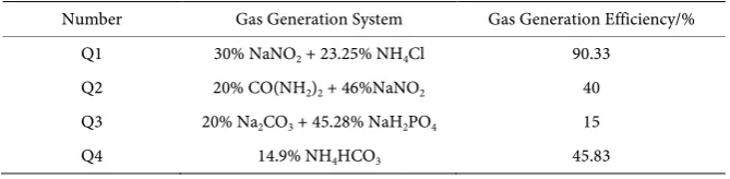
[image:3.595.135.538.333.685.2]The experiment was carried out under the simulated formation conditions of reservoir temperature 65˚C and backpressure 8 MPa. The experimental device of double-pipe plugging is shown in Figure 1.
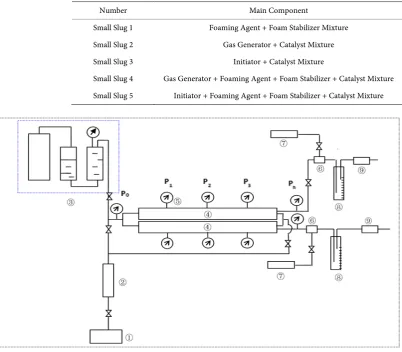
Table 1. The slug design table.
Number Main Component
Small Slug 1 Foaming Agent + Foam Stabilizer Mixture Small Slug 2 Gas Generator + Catalyst Mixture Small Slug 3 Initiator + Catalyst Mixture
Small Slug 4 Gas Generator + Foaming Agent + Foam Stabilizer + Catalyst Mixture Small Slug 5 Initiator + Foaming Agent + Foam Stabilizer + Catalyst Mixture
①: Advection pump; ②: container; ③: Buffer; ④: Reservoir model; ⑤: Precision Pressure Measuring Instrument; ⑥: Backpressure valve; ⑦: Back pressure control; ⑧: Output liquid collector; ⑨: Gas Volume Meter.
DOI: 10.4236/jpee.2019.711006 50 Journal of Power and Energy Engineering The experimental steps are as follows: 1) Fill the two pipe sand filling model (permeability difference is 4), and measure the permeability of two pipes sepa-rately; 2) put the sand filling model at constant temperature 24 h at reservoir temperature; 3) From the outlet of the sand filling model, inject the self streng-thening foam system 0.3 PV, close the valve gate at both ends of the sand filling pipe, and stew well in the reservoir temperature 10 h; and 1 ml/m. The velocity of in is followed up by water flooding from the injection end. The flow rate of the two pipes and the pressure changes at each pressure measuring point are recorded.
2.2.4. EOR Determination
The experimental steps are as follows: 1) Filling double-pipe sand-filling model (permeability range is 4) and measuring the permeability of two pipes separately; 2) Saturating crude oil into two sand-filling pipes respectively, and putting the model at reservoir temperature for 24 hours; 3) Two-pipe water flooding expe-riment is carried out at the injection rate of 1 mL/min until the water production rate reaches 80%; The outlet of the model is injected into the local plugging sys-tem at the rate of 1 mL/min. After the injection is completed, the outlet is closed and the temperature of the reservoir is kept constant for 10 hours; 4) the outlet is opened for production, and the injection end is opened after no liquid produc-tion at the outlet, and the water drive is carried out from the injecproduc-tion end (in-jection rate is 1 mL/min) to the water production rate reaches 98%. 5) The injec-tion seal is calculated. The recovery rate of plugging system is increased.
3. Results and Analysis
3.1. Determination of Autogenic Gas System
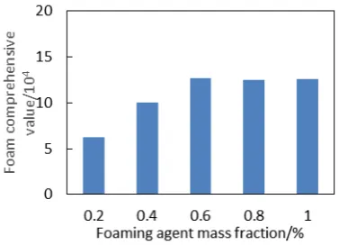
The gas-generating efficiency of the five self-generating systems is shown in Ta-ble 2. The gas-generating efficiency of Q1 (NaNO2 + NH4Cl) system is the
high-est, and the reaction time can be controlled within a certain range. At the same time, it was found that the concentration of sodium citrate catalyst had little ef-fect on the self-gas efficiency. Considering the gas volume and solubility, 30% NaNO2 + 23.25% NH4Cl + 0.1% catalyst was chosen as the self-gas formulation.
3.2. Optimum Selection of Foaming Agent
[image:4.595.206.541.641.723.2]The performance of four foaming agents is shown in Figure 2. It can be seen that COSL-3 foaming agent is superior to the other three foaming agents. Therefore,
Table 2. The gas production efficiency off different self-generating gas systems. Number Gas Generation System Gas Generation Efficiency/%
Q1 30% NaNO2 + 23.25% NH4Cl 90.33
Q2 20% CO(NH2)2 + 46%NaNO2 40
Q3 20% Na2CO3 + 45.28% NaH2PO4 15
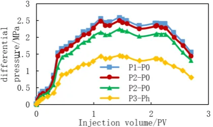
DOI: 10.4236/jpee.2019.711006 51 Journal of Power and Energy Engineering COSL-3 foaming agent is chosen as the foaming agent in this experiment. The performance of COSL-3 foaming agent with different concentration is shown in Figure 3. The optimum concentration of foaming agent is 0.6%.
3.3. Optimum Selection of Foam Stabilizer
As shown in Figure 4, the foam solution foam with HS type HPAM has the highest composite value. Therefore, the HS type HPAM with a mass fraction of 0.25% is chosen as the foam stabilizer for the foam system.
[image:5.595.271.477.221.362.2]According to Figure 5 and Figure 6, the pressure variation curves of the
[image:5.595.280.469.394.530.2]Figure 2. Optimization of foaming agent types.
Figure 3. Optimization of foaming concentration types.
[image:5.595.267.483.561.706.2]DOI: 10.4236/jpee.2019.711006 52 Journal of Power and Energy Engineering Figure 5. Pressure change of pressure measurement point of low permeability pipe.
Figure 6. Pressure change of pressure measurement point of high permeability pipe.
pressure points of the two pipes are compared. It is found that the pressure dif-ference between the pressure measuring points of low permeability pipes and the backpressure is larger than that of the back pressure. The pressure difference between the pressure points 0 and 1, 1 and 2, 2 and 3 is relatively small and bas-ically the same, indicating that the foam plugging agent formed in the low per-meability pipe is mainly distributed at the outlet side, and the pressure difference between the high pressure pipe pressure gauge 0 and 1, 1 and 1 is different from that of the 3 points. The pressure difference between the pressure measuring point 2 and the pressure measuring point 3 and the pressure measuring point 3 and the back pressure increased successively, indicating that the foam plugging agent in the high permeability pipe can reach the middle part of the sand filling model, and can effectively block the rear part of the sand filling model. There-fore, the self strengthening foam system has selective sealing effect on heteroge-neous reservoirs, and mainly plugging high permeability reservoirs.
[image:6.595.270.480.238.363.2]DOI: 10.4236/jpee.2019.711006 53 Journal of Power and Energy Engineering
3.4. Enhanced Oil Recovery
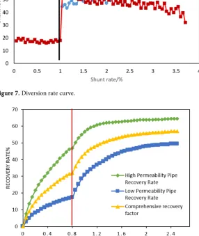
The injection of self foam enhanced foam slug combination to enhance oil re-covery is carried out in a two tube sand filling model (permeability of about 1982 × 10−3 m2 and 475 × 10−3 m2), as shown in Figure 8.
[image:7.595.234.530.184.381.2]According to Figure 8, the recovery rate of self strengthening foam is obtained. The following Table 3 shows that the high permeability pipe (HPP) increases the
[image:7.595.239.526.261.601.2]Figure 7. Diversion rate curve.
Figure 8. Enhanced oil recovery of self-generating enhanced foam.
Table 3. Comparison of recovery rates in different periods. early stage waterflooding
recovery/% subsequent waterflooding recovery/% EOR ratio/%
HPP LPP HPP LPP HPP LPP Total
[image:7.595.205.540.665.731.2]DOI: 10.4236/jpee.2019.711006 54 Journal of Power and Energy Engineering recovery rate by 17.56%, the low permeability pipe (LPP) increases the recovery rate by 32.15%, and improves the recovery ratio by 24.85%.
4. Conclusions
1) Through the optimization of different systems, the formulation of the self strengthening foam system developed is 0.6% COSL-3 foaming agent + 0.25% HPAM + 30% NaNO2 + 23.25% NH4Cl + 0.1% catalyst.
2) The self strengthening foam system has better selective plugging effect on heterogeneous strata under reservoir conditions, and mainly plugging the latter part of the high permeability reservoir.
3) The experiment of increasing oil recovery by plugging water by parallel sand filling pipe shows that the enhanced oil recovery rate of self strengthening foam low permeability pipe can reach 32.15%, and the double pipe comprehen-sive recovery ratio can reach 24.85%. The system has good water plugging effect.
Conflicts of Interest
The authors declare no conflicts of interest regarding the publication of this pa-per.
References
[1] Liu, Y.G., Xu, W.J. and Jiang, W.D. Research and Practice of Regulation and Flood-ing Technology for Offshore Oil Fields. Petroleum Science & Technology Forum. [2] Yu, H., Wang, Y., Ji, W., et al. (2011) Study of a Profile Control Agent Applied in an
Offshore Oilfield. Petroleum Science & Technology, 29, 1285-1297.
https://doi.org/10.1080/10916466.2010.525587
[3] Zhou, M.L., Liu, F., Huang, W., Zhang, C.X. and Deng, Y.X. (2012) Application and Effect Analysis of Profile Control Technology in Chengdao Oilfield. Offshore Oil, 32, 74-78.
[4] Zhao, F.L., Dai, C.L. and Wang, Y.F. (2006) Water Control Technology for Enhanc-ing Oil Recovery in Offshore Oilfields. Journal of China University of Petroleum, Natural Science Edition, 30, 53-58.
[5] Zhang, Z., Han, H., Shen, J., et al. (2014) Study on Adaptability of Nitrogen Foam to Control Profile in Offshore Oilfield. Advances in Petroleum Exploration & Devel-opment, 7, 72-77.
[6] Yang, Z.C., Zheng, J.L. and Weng, D.L. (2017) Self Generating System And Influen-cing Factors of Gas Generation Efficiency of Self Generated CO2 Foam in Bohai Oil Field. Progress in Fine Petrochemical Industry, 18, 38-40.
[7] Xu, G.R., Ju, Y., Pang, C.Y., et al. (2017) Study on Optimization of Self-generating System in Offshore Oilfields. Inner Mongolia Petrochemical Industry, No. 1, 90-93. [8] Zou, B., Liu, D.Q. and Tian, T. (2010) Study on the Performance of High