t
i
I
!!Ir
~
"
,.
I
I
It
.+.
r
l
Edward A/casser
James P. Phillips
Allen M. Walk
Copyright © 1967, 1968
Hayden Book Company, Inc. All rights reserved. This book or any parts thereof may not be reproduced in any form or in any language without permission of the publisher. Library of Congress Catalog Card Number 66-14495.
Preface
The new and exciting field of digital computers has expanded so much in recent years that almost everyone is now affected by it. The need to understand computers experienced by people of widely diversified vocational and academic backgrounds has presented one of the most challenging jobs of teaching ever to be tackled by authors, lecturers, and teachers alike.
As with any new and complicated subject, the first texts to be introduced are usually effective at the college and postgraduate levels. This book, How to Build a Working Digital Computer, is the result of an endeavor to present to the non-engineer the basic facts concerning digital computers, their uses, and how they work. It is specifically aimed at a reader with an interest or need to understand this subject but with no formal training or education in computer technology. How to Build a Working Digital Computer is equally aimed at hobbyists, technicians, secondary school students, and college students with no computer background.
In presenting the topic of basic computer technology, a. unique method of "learning by doing" is employed. Since there is no effective substitute to proving out theory in the laboratory, this book shows the reader how to construct a working model 9f a digital computer, using simple inexpensive components usually found around the house or in a neighborhood electrical parts store. This computer is divided into basic units corresponding to the actual working sections of a computer. The design and operating principles of each computer section are explained in detail using examples and simple experiments and the corresponding model computer unit is then constructed and used to illustrate the theory discussed in the text.
In this manner, a complete working digital computer, able to add, subtract, multiply and perform many other complicated functions at the reader's discre-tion, is constructed. The text then discusses the topic of programming and several basic computer programs are developed for use with the model computer. The reader may write his own programs, load them on his own working computer, and run the programs, providing experience and proving the principles expounded in the text.
With this text, hobbyists, students, technicians, and just ordinary people will find a simplified, enjoyable, and effective approach towards learning and really understanding the basic principles of modern digital computers.
We would like to acknowledge the work done by Scalor Publications in helping to produce the art and tables used in the text.
June, 1967 THE AUTHORS
Table of Contents
Chapter 1. Introduction
The Digital Computer, 1 A Brief History of Numbers and Calculators, 2 Computers in the 20th Century,S Organiza-tion of the Computer, 6 A Sample Computer Program, 8
1
Chapter 2. Communicating with the Computer 13
Number Systems, 13 The Binary Number System, 15 Encod-ing, 16 Decimal to Binary Conversion, 17 The Encoder, 18 Binary to Decimal Conversion, 21 The Decoder, 22
CONSTRUCTION DETAILs-Encoder, 23 Decoder, 31
Chapter 3. Computers and Logic 41
Symbols, 42 Truth Tables, 43 Logic Circuits, 45 Truth
Evaluator, 47 Experiments with Truth Tables, 48 Boolean Algebra, 51 Minimizing Terms, 53 De Morgan's Theorem, 55 The UN Problem-An Experiment in Logic, 57
CONSTRUCTION DETAILs-Truth Evaluator, 59 Battery Holder,
62 UN Problem, 63
Chapter 4. Computer Arithmetic
Binary Arithmetic, 65 Basic Rules, 65 Adding Binary
Num-bers, 67 Subtraction, 71 Complementary Numbers, 74
Multiplication and Division, 75 Arithmetic Unit, 75 CONSTRUCTION DETAILs-Arithmetic Unit, 81
65
Chapter 5. Storage Devices 87
Basic Concepts, 88 Computer Words, 88 The Core Mem-ory,89 The Drum Memory, 91
CONSTRUCTION DETAILS-Core Memory, 93 Drum Memory, 97
Chapter 6. Computer Control
The Computer Units-A Review, 105 The Control Unit, 106 The Complete Instruction Repertoire, 108 Wiring the System, 109 Check-Out Procedures, 111 Operating Procedures, 113 CONSTRUCTION DETAILs-Control Panel, 114 Junction Box, 122 Common Tie-Point' Terminal Strips, 124
Chapter 7. Programming Our Computer
The Programming Process, 126 Using Octal Codes, 129 Devising a Simple Program, 132 Programming Multiplication,
133 Programming Division, 145 Readout, 155
Formulat-ing the Program for Transfer to Drum, 165
Appendices, 167
Index, 173
105
Chapter 1
INTRODUCTION
THE DIGITAL COMPUTER
The progress of man is directly related to the tools and imple-ments he uses in his work. The extremely. large and rapid strides being made today in the development of our technology may be attributed in part to the coming of age of the electronic, programmable, digital computer. This is a "tool" that can be taught or programmed to solve a variety of complex problems rapidly and with great accuracy. In this text, we will detail the construction of a working model of a digital computer and demonstrate the operation of this important machine through discussion and experiment.
Modern computers can perform billions of basic arithmetic opera-tions such as addition or subtraction each second without error or fatigue. They are able to manipulate extensive amounts of data at speeds that operators of calculating machines cannot match. Accuracies achieved are typically rated in terms of one part in a million. Such awesome capa-bilities have led to use of computers in countless areas. As of April, 1965, there were approximately 18,000 computer installations in this country serving the government, science, schools, and industry.
The Internal Revenue Service has estimated that tax revenues were increased by 52.5 million dollars in 1964 because computers were used to process Federal income tax returns. Using computers to make blood tests in laboratories enables technicians to perform tests in two minutes that would ordinarily take two to three hours. A pub-lishing firm that now uses a computer to process book orders estimates that it has reduced its order-processing time by 75 percent. The spec-tacular achievements of our various space programs can be directly related to the computer control of different phases of each operation. The highly satisfactory performances of the Ranger, Gemini, and Mariner missions would not have been possible without computers.
The influence the digital computer is exerting on our society is demonstrated every day on the front pages of our newspapers and. in countless articles and columns relating new computer applications. The . potential future applications of the digital computer will make this
pres-ent widespread use seem small. Before proceeding with our study of the computer, it is well to understand the history of the computer's develop-ment and the relationships between this developdevelop-ment and the culture and technology of these times.
A BRIEF HISTORY OF .NUMBERS AND CALCULATORS
In earliest times, man most likely counted on his fingers. If he wamed to indicate that he had killed two tigers, he would hold up two fingers. His earliest counting methods were probably limited to totals below five. In time, sticks and pebbles were used to extend the range of counts, but the simplicity of the existing social organization kept such usage at a very low level of sophistication. Number symbols and methods of computation were unknown and not needed.
As the farmer and tradesman superseded the hunter, man's require-ments for counting and recording his counts for future use became more complex. Simple tallying methods were replaced by systems in which different symbols were used to represent different counts and these sym-bols were added and subtracted. The early Egyptians (circa 3400 B.C.) devised such a number system using symbols called hieroglyphics. The hieroglyphic symbols representing the numbers 1 through 10 are shown in Fig. 1-1. It is interesting to note the relationship between these writ-ten symbols and counting tallied on the fingers on a hand.
The Romans developed a system of numbers, also illustrated in Fig. 1-1, which should be familiar to you because of its use on clock faces, as chapter numbers, and so on. Calculating with this number system was slow and awkward since large numbers required many symbols. For example, the number 9876 in Roman numerals is MMMMMMMMMDCCCLXXVI (M
=
1000, D=
500, C=
100, L=
50, X=
10, V=
5, I=
O.
The symbols of the numbering system that we use today, the deci-mal, are probably of Hindu-Arabic origin and are therefore referred to as Arabic numerals. Figure 1-1 shows early Hindu and Arabic number symbols for the period about the year 900 A.D. The most important mathematical development attributed to the Hindus is the origin of the concept of the zero, O.
EARLY EARLY EARLY EARLY MODERN EGYPTIAN ROMAN HINDU ARABIC
/ / ::r: 2 /
.J- II 7L
.z
\"3 II/ :zzr ~
,
f 1/1/
:zz
'1/ CS 11/
.:J[ Y 0
/I
{, I I I :;zr
S
7/ I I
7 1111
7lT 7 V
II/ J' II 1/
nIT
<
A11/1
'1 I I I
7Z
<:
qI I I I I I
/0 /l
:r:
Introduction 3
Fig. 1·2. An Egyptian sand calculator.
The development of various number symbols and counting systems was matched by the introduction of counting and calculating aids other than sticks or pebbles. For example, to perform calculations the Egyptians developed a sand calculator consisting of columns of grooves in the sand, as illustrated in Fig. 1-2. The right-hand groove repre-sented quantities from 0 to 9, depending upon the number of pebbles contained in the groove. For example, if four pebbles were contained in the groove, the number represented was 4. The next groove to the left represented 10 times the number of pebbles in the groove. Thus, if there were three pebbles in this groove and one in the right-hand groove, the number 31 was represented. Each succeeding groove to the left represented numbers 10 times that of the preceding groove. Hence, the grooves represented the 1 's, 10's, 100's, and 1000's columns, re-spectively, and so on. This system of counting, the decimal system, is the basic system we employ today.
The Egyptians were not alone in the development of simple calcula-tors. Around 600 B.C., the Chinese developed a calculator called an abacus
(Fig. 1-3). This device consists of a wooden frame strung with beads on wire columns. Each column represents an order or place in the decimal numbering system in the same way the grooves represented decimal places in the sand calculator. The abacus is still used today and skilled operators manipulate it at speeds comparable to those of a mechanical or electric desk calculator.
[image:11.414.116.261.71.158.2]As civilization developed, calculating devices became more sophis-ticated and, correspondingly, demanded a higher degree of intelligence and knowledge from their users. The design theory and potential range of applications of some computing machines developed before the 19th century were similar to that of present-day computers, but the efficiency and speed of the machines was very low.
The first truly mechanical calculator, invented by Blaise Pascal, a French philosopher and mathematician, around 1642, was an adding machine that operated in the decimal numbering system (Fig. 1-4).
Fig. 1-4. Pascal's calculator.
It consisted, essentially, of a series of wheels which added and carried 10's. Shortly after Pascal's invention, another philosopher and mathe-matician, Gottfried von Leibnitz, developed a gear-operated calculator, the stepped reckoner, which allowed for the carry operation between orders or places (Fig. 1-5). In Pascal's machine, multiplication was performed by repeated addition; in Leibnitz's machine, multiplication could be performed directly. Both machines were operated manually.
Fig. 1·5. Von Leibnitz's stepped reckoner.
[image:12.415.166.313.183.280.2] [image:12.415.137.289.409.494.2]Introduction 5
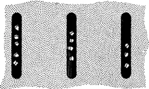
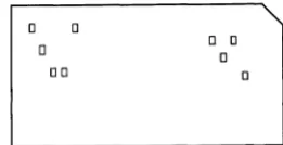
Around 1890 an American scientist working for the Census Bureau, Herman Hollerith, devised a card containing punched holes that could be read or interpreted by an electrical device (Fig. 1-6). Each hole punched into the card represented a different piece of information. After the cards were punched, the data contained on them were read by an
Fig. 1·6. A punched card.
o 0
o
00
o 0
o o
electrical scanner which then ,was able to sort, count, and tabulate the information. This punch card method is used extensively today in data processing applications and was applied successfully to the tabulation of data gathered during the Census of the United States in 1890.
COMPUTERS IN THE 20th CENTURY
After 1890, the development of various types of calculators and data-processing machines proceeded rapidly. However, the machines remained relatively crude as late as the 1920's. They were not capable of performing the long sequences of operations required to solve complex problems and were operated by fairly constant human control.
The first successful computer capable of performing these opera-tions was developed during the period between 1939 and 1944 by the International Business Machines Corporation in cooperation with Harvard University. It was known as the Automatic Sequence-Controlled
Computer or the Harvard Mark 1. It is believed that the development
of this machine was based upon the work done earlier by Charles Babbage and was permitted by the advance of technology by the 1940's which allowed the accuracy in fabrication not available in Babbage's time.
This first, large-scale computer was essentially mechanical in nature using gears, cams, and shaft rotations as the calculating devices, and, therefore, it was relatively slow and bulky. Since then, the use of elec-tronic components has allowed the building of computers that are much faster and less bulky. The first electronic computer was completed in 1946 by the Moore School of Electrical Engineering in Philadelphia and was called ENIAC (Electronic Numerical Integrator and
Calcu-lator). The successful design and fabrication of ENIAC represented a
[image:13.417.191.322.139.206.2]properly. However, in spite of this, ENIAC did operate successfully with approximately 18,000 tubes.
The next major step in the evolution of the digital computer was the advent of the stored-program machine. The word program refers to the series of operations that the computer is instructed to perform. A stored-program machine is built with a facility for storage that allows the insertion of a program at the option of the operator. In this way the solutions to many different problems may be "programmed" and saved for use at appropriate times. Thus, if a problem must be solved for which a program already exists, the operator need only insert the existing program into the computer to obtain the required solution. The idea of the stored-program machine was introduced in 1945 by Dr. John von Neumann. The first stored-program machine was built by a group headed by M. V. Wilkes at Cambridge University in England.
Today's computers are capable of extremely high speeds and accuracy and are used in applications ranging from payroll processing to the guidance of spacecraft. As our technology advances, great strides are being made to increase still further the capability of our computers in terms of information storage capacity, accuracy, and speed. This increase in speed and accuracy allows the computers to solve larger and more complex problems at economical cost and within the most stringent time requirements. Almost every day, major developments are applied toward the creation of computers that can solve greater and more challenging problems. Problems that would require lifetimes to be solved manually are now being solved quickly and efficiently by modern computers. The excitement of our times is certainly aided by the extension given to our minds by computers.
ORGANIZATION OF THE COMPUTER
A digital computer is composed of five basic functional units, as illustrated in Fig. 1-7, the input, storage, arithmetic, control, and output
ORDERS
CONTROL PROGRAMMED INSTRUCTION STORAGE
UNIT CALCULATED DATA UNIT
(FOR TEMPORARY
-STORAGE)
I
ORDERSORDERS STORED DATA
!
ALPHA- ORDERS ~
CALCU-NUMERIC ENCODED LATED
~ INPUT DATA ARITHMETIC DATA OUTPUT
UNIT UNIT UNIT
DECODE~ ~
ANSWER
Introduction
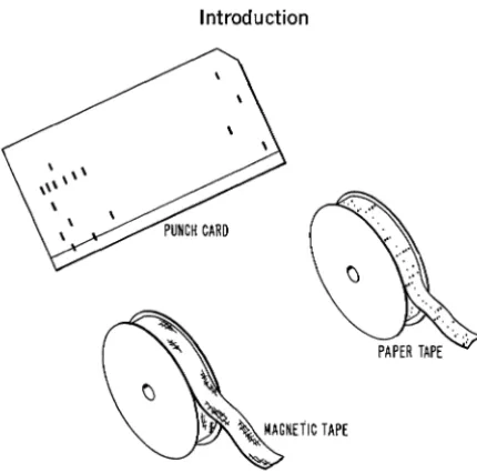
Fig. 1·8. Input methods: (A) paper tape; (8) punched cards; (C) magnetic tape.
7
units. They will be described briefly here and considered in detail in the chapter in which the corresponding unit is constructed for our own com-puter model. The function of the comcom-puter is to accept alphabetical-numerical (alphanumeric) data, perform calculations and other process-ing of these data, and produce specific alphanumeric outputs.
The alphanumeric input data are usually prepared in the form of coded, punched paper tape or cards (Fig. 1-8), or magnetic tape. This information is then converted to electrical signals coded in the binary format (or computer language) used by the computer. The computer unit that receives the alphanumeric data and converts them into the binary format, a process called encoding, is called the input unit. (This
unit is described completely in Chapter 2.) The input unit stores the data until the computer is ready to perform as instructed.
Once the input data have entered the input unit, their paths through the computer and the operations performed upon them are completely determined by the stored program, which indicates the sequence of operations required to perform the desired computations. The program is stored in coded form in the computer's storage unit. Each operation
is read from this storage unit, in sequence, and used by a control unit to
[image:15.418.77.292.45.258.2]The storage unit usually consists of three storage areas: program storage; permanent data storage; and scratch-pad storage. The first area, program storage, is used to store the program for the particular computer application. Programmed operations are stored in a particular fixed sequence so that they may be read from storage automatically in the proper order. The second area, permanent data storage, is used to store various constants and other data required by the program for solution of the problem. The third area, scratch-pad storage, is a tem-porary storage area used by the program to store intermediate results developed during the course of the problem solution.
The various types of memory devices are described in Chapter 5 and a simulated magnetic drum and a core memory unit are designed and constructed. The control unit for our computer is described and constructed in Chapter 6.
The arithmetic unit performs all of the basic arithmetic operations, such as addition, subtraction, multiplication, and division, under program control. Complex mathematical techniques and methods such as the use of calculus are implemented by reducing these techniques to sequences of basic arithmetic operation. (The arithmetic theory of digital com-puters is discussed in Chapter 4, when the arithmetic unit for our computer is constructed.) The output of the arithmetic unit is either stored in scratch-pad storage or read out through the output unit.
The output unit is just the opposite of the input unit in that it performs the function of converting the alphanumeric data from the computer's internal format to that required by the outside environment. Output data are fed to peripheral units such as magnetic tape recorders, printers, typewriters, or card punches, depending on the use these data are put to. (Our computer's output unit is discussed and con-structed in Chapter 2.)
A SAMPLE COMPUTER PROGRAM
Any computer is built specifically to perform a particular set of operations. The list of these operations is called the computer's
instruc-tion repertoire, as it lists the computer's capabilities in terms of the operations it can perform. The instructions contained in the computer's repertoire can be arranged (programmed) in many different sequences to perform all sorts of complex calculations. To illustrate this process, we shall assume that we have a computer that is capable of performing the following instructions:
1. Add the contents stored at location A to those stored at loca-tion B.
Introduction 9
3. Read in data to the input unit. 4. Read out data to the output unit.
5. Store data in location A or in location B, whichever is indicated.
Let us arrange these instructions to develop a program that calcu-lates the solution to the following problem:
T=x+y-z
where x, y, and z are any three numbers. For example, if x = 5, y = 3, and
z
= 4, the solution to the problem is:T=5+3-4
=4
For illustrative purposes we will use these three numbers in our sample program.
First, we must read in and store our numerical inputs, 5 and 3: 1. Read in 5 to the input unit. (Instruction 3)
2. Store 5 in storage location A. (Instruction 5)
3. Read in 3 to the input unit. (Instruction 3)
4. Store 3 in location B. (Instruction 5)
Next, we must add 5 and 3 and store the result:
5. Add the contents of A, 5, to the contents of B, 3, for a total of
8. (Instruction 1)
6. Store 8 in location A. (Instruction 5) This process writes over
the number previously stored in A so that only the new num-ber remains.
Finally, we must subtract 4 from 8 and read the numerical answer out: 7. Read in 4 to the input unit. (Instruction 3)
8. Store 4 in location B. (Instruction 5)
9. Subtract the contents of location B, 4, from the contents of location A, 8, for a remainder of 4 (T = 4). (Instruction 2)
10. Read out 4 to the output unit. (Instruction 4)
With this la-step program inserted in program storage, using
x,
y, andz
instead of set numbers, the computer will automatically calculate T
for any values of
x,
y, andz,
within its capabilities.A diagrammatic representation of the manner in which the data used in this program move through the computer is shown in Figs. 1-9 through 1-14. When the computer is started, the first instruction in the program is read from program storage. This causes the control unit to order the input unit to read 5 (or x) into its own temporary storage facility (Fig. 1-9). If the input data are in decimal form, the input unit encodes these data into the binary form used by the computer.
(Encoding is covered in detail in Chapter 2.)
INPUT 5 (x) (DECIMAL)
'--;ORAGE U ; - l
I
CONTROL READ IN PROGRAM
UNIT
I
STORAGEL _ _ _
ENCODE
I
STORE, - -
---1-I
I DECIMAL TO 5 (x)(BINARY))
I
I
_J
-1
I
I BINARY STORE
ENCODER
I
I
L
_________
INPUT UNI_T _ _ _ _ _ _ _J
Fig. 1·9. Read in x.
be transferred from the input unit to scratch-pad storage location A (Fig. 1-10). Sometimes this transfer may be accomplished via the arith-metic unit for convenience.
Instructions 3 and 4 of the program cause the computer to perform in the same manner as with 1 and 2, reading in and storing 3, or y, in location B of scratch-pad storage.
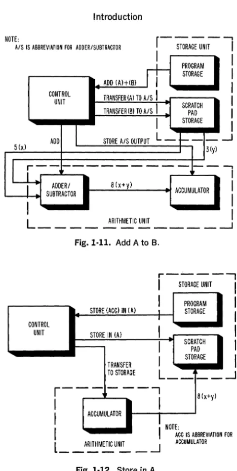
The program's fifth instruction causes both the contents of A and B to be transferred to the arithmetic unit where they are added and their sum stored in the accumulator, a short-term storage element contained in the arithmetic unit (Fig. 1-11). The sixth instruction causes the sum to be transferred to scratch-pad storage location A (Fig. 1-12). Instructions 7 and 8 of the program read in and store data, 4 (or z),
in location B in the same manner as instructions 1 and 2 or 3 and 4.
r - - - ,
I
STORAGE UNIT ICONTROL UNIT
. . _.::.:ST.::.:;OR:::...E::...;5
(c::;X)~IN:..:.(:.:.:.A)_--;.I--I
PROGRAMI
STORE IN (A) I STORAGE ITRANSFER TO STORAGE
r - - I - - - ,
I
I
I STORE I
I
i
INPUT UNIT I
L _ _ _ --I
5 (x)
I
I
~ SCRATCH I
--:---"" PAD
I
STORAGEI
L __
j __
--1
Introduction
NOTE:
A/S IS ABBREVIATION FOR ADDERISUBTRACTOR
ADD (Al+(Bl
n-PROGRAM STORAGE
CONTROL TRANSFER
(A) TO AlS
I
UNITTRANSFER (BlTO AlS
I
SCRATCH PADI
STORAGE ADDI
STORE A/S OUTPUTL -
+- -
-5 (xl 3 (yl
LL---I
SU~~m~OR 8 (x+yl ACCUMULATOR --,I
I
I
I
L
ARITHMETIC UNIT!
- - - '
CONTROL UNIT
Fig. 1·11. Add A to B.
STORE (ACCl IN (Al
STORE IN (Al
TRANSFER TO STORAGE
r----....,
I
STORAGE UNITI
I
PROGRAML STORAGE
I
I
I
SCRATCH PADI
STORAGEL __
-I
I
I
I
I
~r - - -
- - - - ,
8(x+yl
I
I
I
ACCUMULATORI
NOTE:I
l
_ _ _ _ _ _ ARITHMETIC UNIT --.J IFig. 1·12. Store in A.
ACC IS ABBREVIATION FOR ACCUMULATOR
11
Instruction 9 causes the contents of B to be subtracted from those of
[image:19.422.67.307.40.516.2]8(x+y)
CONTROL UNIT
SUBTRACT
I
r
-STORAGEiiNIT-1I
SUBTRACT (AHB)
rr--PROGRAM STORAGE
TRANSFER (A) TO AlS
I
TRANSFER (B) TO AlS
I
SCRATCH PADI
STORAGE STORE A/S OUTPUTL -,
+--
-4 (z)
I
I
I
I
I
-.J
LL---
I
8 4 • 4I
ADDERI (X+y) -(Z)·(T)I
SUBTRACTOR ACCUMULATOR
CONTROL UNIT
Fig. 1·13. Subtract B from A.
r---;;:ORAGE UNIT
-1
I,
I
. . _...:.::RE:.::;AD.:.,:OU.:....T _ _ -+--1 PROGRAM
I
I STORAGEI
I
TRANSFER
IIL--___
D~EC:::::OO~E
_ _ _ _L_-_::.:;_ - --'
TO OUTPUTUNIT --i.2TORE
r--'-~
--"""1
r-. ---,
I
8 4·4I
I
(x+yHZHTl OUTPUT BINARYTOI
ACCUMULATOR II
STORET
DECIMALI
\ ,DECODER
L
____
J
l
""'-~=-·4·(T)(BINARY)
_ _J
Fig. 1·14. Read out.
OECIMAL OUTPUT
Chapter 2
COMMUNICATING
WITH THE COMPUTER
The only "language" that the computer uses is numerical. All of the information fed into it must be converted to number form. However, as indicated in Chapter 1, the digital computer does not operate in the decimal number system. Any numerical data given to it must be translated from our decimal language into the binary language of the computer. All information taken from the computer must be translated from the machine's language into our own. In a like manner, alphabetic data must be converted to a, binary numerical code for use in the computer. In this chapter, only numerical data will be considered. OUf computer has two translating devices, the encoder and the
decoder. The encoder enables us to translate our problem data from decimal numbers to binary numbers. The decoder enables us to under-stand the answers the computer obtains by translating its binary response into decimal numbers. To understand how these units function, it is necessary to examine the relationship between the decimal and binary number systems.
NUMBER SYSTEMS
In the decimal number system, there are ten different numeral symbols: 0, 1, 2, 3, 4, 5, 6, 7, 8, and 9. When standing alone, each of these symbols represents a fixed number. In combination, however, these symbols can represent any number in the system. They do so by assuming different values when placed in different positions in a number. For example, in the number 4444, the numeral symbol is the same but it has four different values: 4000, 400, 40, and 4. In the decimal num-ber 255,252, two numeral symbols are used, but each has more than one value (200,000,200, and 2; 50,000, 5,000, and 50).
Such a system, where the value of the numerical symbol is deter-mined by its position, uses positional notation. The significance of positional notation in the decimal number system is shown in Fig. 2-1. The first column to the left of the decimal point is the 10° or unit's column. Any numeral that appears in this position is weighted by the factor 1. The numeral 6 in this column is the equivalent of 6 Xl, or 6 X 10°. In the second column to the left of the decimal point, the 101 column, a numeral is weighted by a factor of 10. Here, 6 would
DECIMAL
HUNDREDS TENS UNITS POINT TENTHS HUNDRETHS COLUMN COLUMN
(102) (101)
COLUMN I
(10°) ...
COLUMN COLUMN
(10-1) (10-2 )
° .
60-6110-60
o • 60'10 • 600
Fig. 2-1. Positional notation in the decimal number system.
attain a value of 6 X 10, or 6 X 101 • In the third column, the 102
column, 6 would attain a value of 6 X 100, or 6 X 10² •
Each of the numeral symbols in the decimal system will change its value in the same manner as its position changes in a number. Each shift to the left increases a numeral's value by a factor of 10. Each shift to the right decreases a numeral's value by the same factor. To illustrate this further, we will break down several decimal numbers:
357.1
=
300+
50+
7+
0.1=
3 X 100+
5 X 10+
7 X 1+
1 X 1/10= 3 X 10²
+
5 X 101+
7 X 10°+
1 X 10-113402.01
=
10,000+
3000+
400+
2+
.01=
1 X 10,000+
3 X 1000+
4 X 100+
2 X 1+
1 X 1/100= 1 X 10⁴
+
3 X 10³+
4 X 10²+
0 X 101+
2 X 100+
0 X 10-1+
1 X 10⁻²Many practical number systems use positional notation. They differ from the decimal system only in the number of numeral symbols they use and the weighting factor related to each position. The octal system, for example, uses 8 symbols: 0, 1,2, 3,4, 5, 6, and 7. Numeral values in this system change by a factor of 8 as the numeral's position changes. For example, the octal number 136 is the equivalent of the decimal number 94:
136
=
1 X 82+
3 X 81+
6 X 8°=
1 X 64+
3 X 8+
6 X 1=
94Communicating with the Computer 15
used in the system and is referred to as the system's base or radix. The base for the decimal system is 10; the base for the octal system is 8. Using this coding, for example, (IOOho and (l00)g represent, respec-tively:
and:
1 X 10² + 0 X 101 + 0 X 10°
1 X 82 + 0 X
81 + 0 X 8°
Also, (100)g = (64ho.
Any number in any positional notation system may be represented by the following formula:
N = SnBn + ... + S3B3 + S2B2 + SIB! + SoBo + S_IB-l + S_2B-2 + ... + S_mB-m
where N is the number, Sn through S-m are the numeral symbols used in the system, and B is the base of the system. The base, raised to a power, represents the factor by which the numeral symbol is multiplied in each position. In these number systems, the least significant numeral is the rightmost digit and the most significant numeral is the leftmost digit.
THE BINARY NUMBER SYSTEM
Like the octal and decimal systems, the binary system uses posi-tional notation. Two symbols, only, are used, 0 and 1, so the value of a numeral increases or decreases by a factor of 2 as it shifts to the left or right. The base of the binary system is 2. The significance of posi-tional notation in the binary system is shown in Fig. 2-2. To illustrate this further, we will break down several binary numbers.
(1l01)z = 1 X 23 + 1 X 22 + 0 X 21 + 1 X 20
=IX8+1x4+0X2+1Xl
=
(l3ho(10011)2 = 1 X 24 + 0 X 23 + 0 X 22 + 1 X 21
+
1 X 2°=IXI6+0X8+0X4+1X2+1Xl
=
(19hoTABLE 2-1
BINARY DECIMAL BINARY DECIMAL
1 1 10001 17
10 2 10010 18
11 3 10011 19
100 4 10100 20
101 5
110 6 11110 30
111 7 110010 50
1000 8 1000110 70
1001 9 1011010 90
1010 10 1100100 100
1011 11
1100 12 1111101 125
1101 13 10010110 150
1110 14
1111 15 111110100 500
10000 16 1111101000 1000
Each numeral in a binary number is referred to as a bit (binary
digit). The binary number 100, which is (4
ho,
is a three-bit number, and 10100, or (20ho, is a five-bit number. Computers are rated by the number of bits that can be stored in their memory sections. The capacity for bit storage is directly related to the computer's precision and ability to handle complex calculations. Larger· capacities enable the computer to work with greater precision and more complex calculations.As indicated in Table 2-1, which lists some binary numbers and their decimal equivalents, binary numbers use more digits than decimal numbers to express the same quantities. However, the advantages this may give to decimal numbers are offset, in a computer, by the ease with which arithmetic is performed in the binary system. This will be covered in more detail in Chapter 4.
Because the decimal and binary number systems both use positional notation, conversion from one system to the other is relatively simple. It is done by translating the numeral values of one system into those of the other.
ENCODING
Communicating with the Computer 17
that performs this function accepts data in one form and transmits them in another. Its output is the properly-coded equivalent of its input.
The simple alphabet codes you may have used in childhood involved an encoding process. Converting such meaningful phrases as:
The ball was thrown from first to third.
into:
Ftg nmzz ime ftdaiz rday rudef fa ftudp.
used a conversion system in which a generally known arrangement of letters was converted into a generally unknown arrangement of letters. A relationship was established between both letter systems so that any sentence could be converted and still be understandable when decoded. (In this case, the known letters, a, b, c, ... , n, 0, p, ... , z are the equivalent of the coded letters m, n, 0, . . . , z, a, b, . . . , 1, respectively. )
Encoding in a computer follows the same kind of fixed relation-ship. Each known decimal number corresponds to a "coded" or binary number.
DECIMAL TO BINARY CONVERSION
Decimal numbers can be converted to binary numbers by using the general number equation for the binary number system:
*
To do so, you would set N in the equation equal to the decimal number and solve for all the terms. If you wish to work this out for any par-ticular decimal number, do so, but you will find that the process is quite lengthy and time-consuming.
There is a short-hand method for decimal to binary conversion that simplifies the exercise considerably. In it, the decimal number to be converted is repeatedly divided by 2. The remainder of each division, which can only be 1 or 0, will indicate a digit of the binary number. The remainder of the first division is placed in the 2° column; the remainder of the second is in the 21 column; etc. For example, to convert (128) 10 into its binary equivalent, the following steps are
followed:
Division Remainder Position
2 \ 128 0 20
2 \...§±.. 0 21
2\.13.... 0 22
2\.12.... 0 23
Division Remainder Position
2\L 0 24
2\£ 0 25
2\.L 0 26
2\..L 1 27
Therefore, (l28ho
=
(lOOOOOOOhLet us try this with a different number. For instance, (61 ho:
Division Remainder
2~ 1
2~ 0
2~ 1
2\1- 1
2\L 1
2\!.. 1
Therefore, (61ho
=
(111101h.THE ENCODER
Position
20 21 22 23 24 25
The encoder for our computer will convert the decimal numbers
o
through 9 into their binary equivalents. The construction details for this unit are given at the end of this chapter. At this point we will consider its design aspects.The encoder unit receives a decimal input and produces an equiv-alent binary output. Switches will be used to represent and manipulate the decimal input. To monitor its output and demonstrate its function, the encoder will have a display that indicates what binary numbers are being used. Lamps will be used to indicate this binary output. Since a lamp has two states-on and off-and a binary number has two symbols - 0 and 1, we will indicate a 1 symbol by lighting the lamp and a 0 symbol by extinguishing it.
We know that the largest decimal number we will encode is 9 and that its binary equivalent is a 4-bit number, (l001). Four lamps will therefore be sufficient for the binary output, one for each bit posi-tion. The lamps will be labeled according to their column heading: 23,22,2\ and 2°.
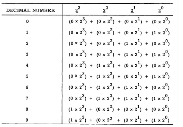
The switch connections used to encode decimal numbers are deter-mined by examination of a conversion chart, such as that shown in Table 2-2. This reveals that there is some pattern to the manner in which the four output lamps indicate D's or l's. In the 2° column (rightmost column), the D's and 1 's alternate. For an even number there is a 0, for an odd there is a 1. In the next column, the 21 column, the D's and 1 's run down the column by twos. In the 22 column the D's and 1 's run down the column by fours. In the 23 column, the first eight
Communicating with the Computer 19
TABLE 2-2
DECIMAL NUMBER ~3 ~2 ~1 ~O
° (0 x 2 3) + (0 x 22) + (0 x 21) + (0 x 2°) 1 (0 x 2 3) + (0 x 2 ) 2 + (0 x 21) + (1 x 2°) 2 (0 x 2 3) + (0 x 2 ) 2 + (1 x 21) + (0 x 2°) 3 (0 x 2 3) + (0 x 22) + (1 x 21) + (1 x 2°) 4 (0 x 2 3) + (1 x 22) + (0 x 21) + (0 x 2°) 5 (0 x 2 3) + (1 x 22) + (0 x 21) + (1 x 2°) 6 (0 x 2 3) + (1 x 22) + (1 x 21) + (0 x 2°)
7 (0 x 2 3) + (1 x 22) + (1 x 2 ) 1 + (1 x 2°) 8 (1 x 2 3) + (0 x 22) + (0 x 21) + (0 x 2°) 9 (1 x 2 3) + (0 x 22 + (0 x 21) + (1 x 2°)
rows that the pattern is not apparent for this column. If we had extended the chart to sixteen rows, we would have eight rows of 1 'So
A ten-position rotary switch is used in the encoder. This switch is similar to the channel selector on a TV set where each channel is a particular position on the switch. A rotary switch has two parts: the arm and the contacts. Usually, one end of the arm is connected to a single point on a common terminal and rotates about this point. As it rotates, it contacts connection points that are positioned in a circle around the common terminal. A schematic of a ten-position rotary switch is shown in Fig. 2-3. You can see that the arm serves to connect the contact terminals to the common terminal, one at a time.
Fig. 2·3. A ten-posi-tion rotary switch.
[image:27.417.36.343.91.304.2]B+
Fig. 2-4. A rotary switch wired to light 20 with every odd number.
lamp. To form a complete circuit, the other side of the lamp is con-nected directly to the power source return.
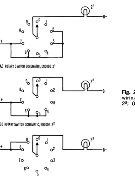
The 21 lamp wi11light only when the decimal numbers 2, 3, 6, or 7 are encoded. The rotary switch connections for this lamp are shown in Fig. 2-5A.
The 22 lamp wi11light only when the decimal numbers 4, 5, 6, or 7 are encoded. The 23 lamp lights only when the decimal numbers 8 or 9
are encoded. The rotary switch connections for these lamps are shown in Fig. 2-5B and C, respectively.
~:---~B-'0
li'
d
B::..;.+_t--, 8
1
:o:
'r
~ ~
j
(A) ROTARY SWITCH SCHEMATIC, ENCODE 21
90
It
d
80
\l
02 L---~B-::..,;B+ _ _ ....:.7003
(B) ROTARY SWITCH SCHEMATIC,ENCODE 22
'cr
d
B+
02
U
L---~B-70 03
SO
0 04
5
(e) ROTARY SWITCH SCHEMATIC,ENCODE 23
Fig. 2·5. The rotary switch wiring to lamp (A) 21; (8)
[image:28.415.80.299.281.572.2]Communicating with the Computer 21
To encode the decimal numbers 0 through 9, therefore, four ten-position rotary switches are needed. However, since this means that we must run each switch to the same position to encode a number, the construction is a bit cumbersome. Therefore, the switches are ganged; i.e., they are combined so that the arm is common to all four switches.
Our encoder will encode two decimal numbers simultaneously. Therefore, it will use two ganged rotary switches and two output dis-plays. The wiring diagrams and a picture of the finished unit are included in the construction details at the end of this chapter.
BINARY TO DECIMAL CONVERSION
In the computer, decoding is necessary because the response is in binary form and must be converted to decimal form to be understood by the user. The unit that performs this function in our computer is the decoder, or output unit.
Arithmetically, converting binary numbers to decimal numbers is not too difficult. The process is one of simple addition:
(1l01l)z = 1 X 24 + 1 X 23 + 0 X 22 + 1 X 21 + 1 X 20
=lX16+1X8+0X4+1X2+1X1 = 16+ 8 +2 + 1
= (27ho
(l0101)z = 1 X 24 + 0 X 23 + 1 X 22 + 0 X 21 + 1 X 20
=lX16+0X8+1X4+OX2+1X1 =16+4+1
= (21ho
If we limit our consideration to numbers under (10) 10, a simple
decoder may be designed in a manner similar to that of the encoder. However, since our computer will be capable of producing numerical outputs exceeding (10) 10, but less than (100) 10, it will be necessary to decode a maximum of a 7 -bit number into a 2-digit decimal number. One method of performing this conversion consists of converting the 7 -bit binary number into two 4-bit binary numbers such that each 4-bit binary number represents a decimal digit. For example, the 7-bit num-ber (0101011)2 or (43)10, may be converted to the following 4-bit numbers.
0100 and 0011 (or (4ho and (3ho)
This conversion is usually performed by a programmed sequence of operations and is discussed in Chapter 7. The 4-bit numbers each represent a decimal digit and are called binary-coded decimal numbers.
TABLE 2-3
BINARY SYMBOLS
2 3 22 21 20 DECIMAL SYMBOLS
0 0 0 0 0
0 0 0 1 1
0 0 1 0 2
0 0 1 1 3
0 1 0 0 4
0 1 0 1 5
0 1 1 0 6
0 1 1 1 7
1 0 0 0 8
1 0 0 1 9
THE DECODER
The decoder for our computer will convert the binary numbers 0000 through 1001 to their decimal equivalents. As in the encoder, switches will be used to manipulate and represent the unit's binary input and lamps will be used to display the decimal output. Table 2-3 indicates the binary-to-decimal conversions possible in our computer. Because our computer output will consist of a maximum of two binary-coded decimal digits it will be necessary to have two conversion units and two output displays; one for each four-bit binary output. The two units are composed of four double-throw multipole switches. Each switch represents a digit in a four-bit binary number. When the switch is thrown to the left it represents a 0, when it is thrown to the right it represents a 1. The switches are connected to ten lamps repre-senting the ten decimal numbers
a
through 9. The binary numbers "written" by the switches will light the bulb representing their equivalent decimal number.Communicating with the Computer
CONSTRUCTION DETAILS-ENCODER
COMPONENTS: Chassis, rotary switches, display circuit
MATERIALS
Chassis: 2 6 12
5 X 8 X YII in. composition boards
% in. dowels, 2Y11 in. long (height of spool
+
~ in.) 1h in. wood screws (no. 4)Rotary switches (2):
2 thread spools, empty (l1h in. diameter, I'M! in. height) 2 ~ in. dowels, 3Y11 in. long (height of spool
+
1 ~ in.) 2 1 in. wood screws (no. 4)5 ft. uninsulated hook-up wire (20 gage) Adhesive tape, 2 in. wide
Display circuit:
8 #48 or 41 lamps (2 v, .06 a) 16 paper clips (large)
2 7 X 1h in. tin strips (from can or sheet)
5 ft. insulated hook-up wire (20 gage) 1 ft. uninsulated hook-up wire (20 gage) 4 1h in. machine screws (6-32)
2 1 in. machine screws (6-32) 12 nuts (6-32)
SPECIAL TOOLS: Tin snips
Drill (1116,3/32, YII,~, %)
Razor blade
Steel-edged ruler or straightedge Round file
Chassis Construction
23
One of the 5 X 8 in. boards will hold the lamp display and switch controls. The other will hold the two rotary switches in position underneath the top panel. The dimensions for this unit are controlled by the size of the spools used for the rotary switches. If the recommended spool (l1h in. diameter, I'M! in. height) is not available, the placement and length of the supporting dowels wilI have to be altered to accommodate the larger or smaller spool size.
1. Select your top panel and mark and start the drill holes indicated in Fig. A-I.
2. Drill the %-in. and lis-in. holes in the top panel. (The %-in. holes will hold the lamps for the encoder display. The lis-in.· holes will hold machine screws for circuit and terminal connections.)
COMPOSITION BOARD: 5" X 8"
~---_ _ ~ _ _ _ _ _ _ _ _ ~L-_ _ ~~ SIZE CODE + ~~ DIA
x 3'32 DIA
o I,~' DIA
*
3t8 DIAFig. A-I.
cleanly through both boards. (The 3/32-in. holes will hold the wood screws securing the dowel supports. The 1.4 -in. holes will secure the axes of the rotary switches.)
4. With a round file, open up the 1.4 -in, holes in both boards so that a 1.4 -in. dowel will turn freely in them, Smooth off all rough edges around drilled holes.
Rotary Switch Construction
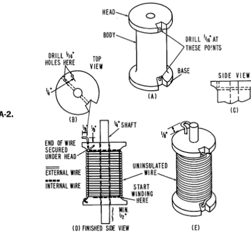
The construction details for both switches are the same. 1. Notch the spools as shown in Fig. A-2(a).
2. Drill a 1/ 16-in. hole through the diameter of the spool at the head and base, starting at the foot of each notch (Fig, A-2(a».
3. On the head of the spool, drill a 1/ 16-in. hole opposite the notch into the head so that the drill comes out close to the hole drilled through the spool's diameter (Fig, A-2(b and c». Drill a second hole down into the head 1;4 in. away.
4. Cut a 3 Ys -in. length of 1.4 -in, doweling and insert it through the spool's center hole. Allow at least Y2 in. to protrude from the base (Fig. A-2(d». (If the dowel does not fit snugly in the spool, wrap tin foil around it for a tight fit. It may help to file the inside of the spool's center hole to remove any burrs created by the drill, It is important that the dowel does not move independently of the spooL If desired, secure it with wood cement or wedges,)
5. When the dowel is secured properly, drill a 1/ 16-in. hole through the doweling at the bottom of the spool, using the hole drilled through the base of the spool in Step 2 as a guide.
6. Insert one end of the uninsulated wire into the hole opposite the notch on the spool's bottom and push it through so that it protrudes slightly from the other side.
Fig. A·2.
Communicating with the Computer
I ' 4
END OF WIRE SECURED UNDER HEAD
HEAD
BODY
IA)
UNINSULATED ...--- WIRE
START WINDING
HERE
I D) FINISHED SIDE VIEW
DR I LL 1'16 AT THESE PO!NTS
SIDE VIEW 25
liti
IC)Fig. A-2(d). Before the spool body is completely covered by unin-sulated wire, drill a 1116-in. hole through the doweling at the top of the spool, using the hole drilled in Step 2 through the head of the spool as a guide.
S. When you have covered the spool body to the hole drilled in Step 7, cut the wire, leaving approximately 3 in. to the end.
9. Insert the end of the wire into the top diameter hole at the notched side and push it through. Pull the wire so that all the windings are taut against the spool body. Then, insert the end of the wire into the 1116-in. hole under the head of the spool and push it through so that it comes out on top of the spool.
10. Insert the end of the wire into the second hole in the spool's head and push it through until a 14 -in. loop is left on the top of the spool. See Fig. A-2(d). Secure the end of the wire by bending it under the head of the spool. Cut off any excess wire protruding beyond the head. Trim off the wire protruding at the bottom of the spool.
11. Bend the 14-in. loop outward as in Fig. A-2(d). 12. Construct a second rotary switch.
Chassis Supports
1. Cut 6 2Vs-in. lengths from the ¥S-in. doweling. (If your spools are not the recommended size, these supports should be 14 in. longer than the height of the spool.)
~/8'
-I I-TOP I~ SUPPORT
~ /
DRill
x 3/32'
Fig. A·a.
A
0
2°
0
TB4 TB3 TB2
0 0 0
0 0 0
0
21 22 23
0 00 0
TBI
Fig. A-4,
3. MarK off four of these supports as shown in Fig. A-3.
ADHESIVE TAPE
UNDERSIDE OF TOP PANEL
4. Drill through the diameter of these four supports, where marked, with a 3/32-in. drill.
5. Secure the six supports to the bottom of the chassis with 1h -in. wood screws. The four supports drilled in Step 4 should be placed next to the y<\-in. holes. The spacer should be at the top.
Display Lamp Construction
1. The eight display lamps will be placed in the % -in. holes in the top panel so that their glass envelopes protrude approximately Ys in. to Y<\ in. above the board. Test each hole with a bulb, and file it as needed to fit the bulb properly.
2. Label the holes on the underside of the panel as indicated in Fig. A-4. This can be done by placing strips of adhesive tape on the board and printing the proper labels on the tape.
3. For each bulb, construct a base terminal connector as follows. Straighten out a paper clip as shown in Fig. A-5(a) and cut it as indicated. Secure the paper clip around the screw base of the lamp as in Fig. A-5(b) and crimp it as in Fig. A·5(c) to hold the bulb firmly. With your long-nose pliers, turn down the cut ends of the paper clip as shown in Fig. A-5(d). When connecting a lead to the bulb, place the stripped end of the lead in the angle formed by the clip ends and bend them until the wire is pinched between them (Fig. A-5(e)). This type of base connection will be used in all lamp displays on all units of the computer.
CUT
fj='
=='\
~rori::
(A) (B)
(C)
(0)
Communicating with the Computer 27
000
TB2 T83 TB4
o
000
o
o
000
o
Fig. A·6. (B)
4. Place the eight lamps, with the base terminal connectors attached, in the % -in. holes on the panel top so that their glass envelopes protrude approximately lis in. to 1,4 in. above the panel.
5. Position the lamps so that the base connectors point towards the 1,4 -in. holes at the foot of the panel.
6. Cut -two 7-in. strips of tin, Vz in. wide. Buff both sides of each strip.
7. Shape each strip as indicated in Fig. A-6(a). When attached to the top panel, these strips should contact only the terminal on the bottom of the lamp. They should not touch the threaded section of the base or the base terminal connector.
8. Fit each tin strip onto the board, running them beneath the lamps, as shown in Fig. A-6(a).
9. Drill through the center of each strip between the 21 and 22 lamps, using the VB -in. holes on the panel as a guide.
10. Insert I-in. machine screws through these holes in the top panel and strips and secure the strips to the lamp bottom terminal with two nuts (Fig. A-6(a)).
11. Screw Vz -in. machine screws into the 3 VB -in. holes at the top of the panel (TB2, TB3, and TB4). Secure these screws with nuts beneath the panel. Connect insulated leads from TB3 to the I-in. screw securing the A strip and from TB4 to the I-in. screw securing the B strip.
12. Cut 8 20-in. lengths of insulated wire. Strip 1,4 in. of insulation from each end of each wire.
13. Label the wires by attaching small pieces of adhesive tape to each end of each wire. Mark the labels with the lamp designations given in Fig. A-4 (A2°, B2°, etc.).
14. Attach the wires to the paper-clip lamp connectors. Lead the wires from the A strip to the left and the wires from the B strip to the right.
Tape Preparation
2. Using the paper with the body dimensions marked on it, divide the height into four equal levels and the circumference into ten equal levels. See Fig. A-7(a).
2 3 4 5 6 7 8 9
1;
1 1 1 1 1 1 1 1 1 1I
I
"'!~"'
:~
SPOOL1---CIRCUMFERENCE---I1
2° 21 22
o I
(A)
2 3 4 5 6 7 8
23 I-+--+--t-~
Fig. A·7.
3. Mark the ruled paper in the fashion shown in Fig. A-7(b). This is the template pattern for the adhesive-tape insulation that will cover the uninsulated wires wrapped around the spool.
4. Place a length of 2-in. wide adhesive tape that is slightly longer than the circumference of the spool on a metal surface, sticky side down, and cover it with a second layer of 2-in. tape.
5. Lay the paper template on top of the tape layers and cut out the template and tape with a sharp razor and steel-edged ruler along the heavy lines indicated in Fig. A-7(b).
6. Peel both layers of tape from the metal surface as one unit. Be careful that the tape does not tear at the narrow points.
7. Repeat these steps to make a double-layered covering for the second rotary switch.
Placing Tape on Spool Body
Care must be taken when selecting where the tape is to be placed on the spool body. This depends on which spool is to be used for which input (A or B). Input A will be on the left side of the chassis. The design for A is such that 0 is at 12 o'clock and the numbers run clockwise to 9. The switch contact point, however, is between 7 and 8 o'clock.
12 12
ge)<~l
LOOP 7 6 6 5
INPUT A INPUT 8
Communicating with the Computer 29
1. Insert the spool shafts in the 1;4-in. holes drilled in the bottom board so that the spool bottom is flush with the board. Place the top panel so that the top shafts of the spools run through the 1;4 -in. holes and the panel rests on the dowel supports.
2. Rotate the spool to be used as the A input (on the left) so that the wire loop on the top is positioned at about 8 o'clock. Rotate spool B so that the loop is positioned at 5 o'clock. See Fig. A-8(a).
3. On spool A, mark the area between 7 and 8 o'clock "0." On spool B, mark the area between 4 and 5 o'clock "0."
4. Remove both spools and attach the tapes to them. Position the 0 part of the tape where you marked O. The 2° row; which alternates tape and no tape, is to be at the top of each spool. See Fig. A-8(b).
Switch Connections
1. Place the rotary switches on the bottom board. File off any spool shaft that protrudes below the board.
2. Position the panel top over the switches, with shafts in the proper place, and fasten the top to the chassis supports with lh -in wood screws. 3. Straighten 8 large paper clips and cut each one so that it is approximately
3 in. long.
4. Run the paper clips through the holes drilled in the dowels next to the switches. Position the dowels so that the clips appear as in Fig. A-9. 5. Bend the clips for contact on the switch surface as shown in Fig. A-9. Each clip should make contact with the switch approximately in the center of a horizontal row on the patterned insulation. The contacts should be aligned vertically as well as horizontally.
6. Tighten and secure the switch contacts by binding the clip ends around the dowels.
7. Connect the wires from the lamp displays to the switches by attaching the stripped ends to the ends of the paper clips.
8. Cut two 6-in. insulated leads. Strip 1;4 in. of the insulation from both ends of each and coil each wire.
9. Attach one end of one wire to the loop on top of spool A. Attach one end of the other wire to the loop on top of spool B. (See Fig. A-lO.) 10. Put a 112 -in. machine screw through the drill hole for TB 1 and attach
the free ends of the coiled wire to it with a nut. 11. Run a 4-inch insulated lead between TBI and TB2.
Fig. A-9.
ill
"
rn
l!l~
IT]rn
ITl
rn
[§Jm[!]
INPUT A ..
Fig. A-12.
Knobs and Labels
1. Position switches A and B so that the contacts rest on
o
.
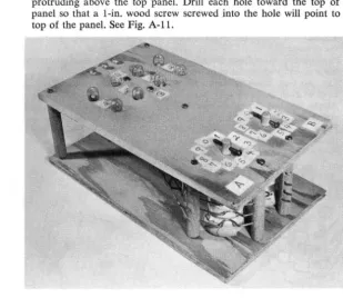
With theswitches held in this position, drill a 3/32-in. hole through each dowel
protruding above the top panel. Drill each hole toward the top of the panel so that a I-in. wood screw screwed into the hole will point to the top of the panel. See Fig. A-Ii.
[image:38.413.63.382.58.280.2] [image:38.413.62.371.309.576.2]Communicating with the Computer 31
2. Put a I-in. wood screw through the holes drilled in Step 1. 3. Label the top panel as shown in Fig. A-I2.
4. To prevent the switch pick-up from fouling, put mechanical stops between 0 and 9 of each switch. These can be I-in. brads nailed into the top of the chassis. Do not drive the nails in too far.
Encoder Checkout Procedure
1. Connect a Ph-volt flashlight battery between the RTN and A terminals. 2. Set switch A to each position and check lamps to see that they light as
indicated below (0
=
off, 1=
on), Switch Positiono
1 2 3 4 5 6 7 8 9 23o
o
o
o
o
o
o
o
1 I Lamps 22 21o
0o
0o
1o
1I 0
I 0
I 1
1 I
o
0o
02°
o
1o
1o
1o
Io
13. Repeat Steps I and 2 for switch B, connecting the battery between the RTN and B terminals.
CONSTRUCTION DETAILS-DECODER
COMPONENTS: Switch chassis, switches, display chassis, display circuit
MATERIALS
Switch chassis and switches:
1 15 X 15 X VB in. composition board 1 15 X 4 X V<! in. composition board 4 5 X 1-2 X VB in. composition board 4 3 X 1-2 X VB in. composition board
20 ft. insulated hook-up wire (20 gage) 12 DPDT switches
2 SPDT switches
32 1-2-in. wood screws (no. 4) 2 1-2-in. machine screws (6-32) 8 %-in. machine screws (6-32) 12 nuts (6-32)
Display chassis and circuit:
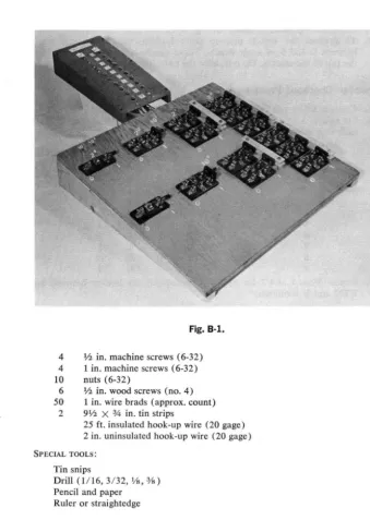
Fig. B-1.
4 1/2 in. machine screws (6-32)
4 1 in. machine screws (6-32)
10 nuts (6-32)
6 ~ in. wood screws (no. 4) 50 1 in. wire brads (approx. count)
2 9~ X % in. tin strips
25 ft. insulated hook-up wire (20 gage) 2 in. uninsulated hook-up wire (20 gage)
SPECIAL TOOLS:
Tin snips
Drill (1/16, 3/32, lh, ¥s)
Pencil and paper Ruler or straightedge
Switch Chassis Construction
This panel will hold an array of single-pole, double-throw (SPDT) and
double-pole, double-throw (DPDT) switches. The unit is designed for knife
[image:40.423.43.383.60.538.2]Fig. B·2.
Communicating with the Computer
COMMON
TERMINALS ....,::::::....:~--=:~;;;;;;;." NO.3
SECURING HOLE
33
SECURING HOLE
TERMINALS NO. 2
simple, home-made switches. The double-pole, double-throw model of this switch is shown in Fig. B-2.
*
1. The switches are arranged on the panel as shown in Fig. B-3. Mark the 15 X 15 X Vs-in. panel on its top (smooth side) as shown in Fig. B-3. Then, using the figure as a guide, position a DPDT or SPDT switch where indicated and mark the position of the switch-securing holes with a sharp pencil.
Fig. B·3.
2. Start a drill hole at each pencil mark, then drill through the panel with a 3/32-in. drill at each point.
3. Start drill holes at all other points indicated in Fig. B-3 and drill through the panel with the designated drill.
4. Mark the 15 X 4 X V<I-in. board as in Fig. B-4 and cut along the diagonal line. These angle supports will support the switch panel. 5. Placing the wide ends of the supports at the top of the panel, drill
1/ 16-in. holes along the top edge of each support, using the holes drilled at the panel side edges in Step 3 as guides.
6. Secure the angle supports to the panel with lh -in. wood screws. 7. Attach all switches, using lh-in. wood screws.
r
i
h~
________________
~j
1 0 - 1 ---15·---t~
Fig. B·4.
8. Mark for drill holes alongside each switch terminal of each switch. Drill these holes through the panel with the Vs-in. bit.
9. As different sets of switches are to be thrown simultaneously, their handles must be joined. Connect the switch indicated in Fig. B-5(a)
in the manner detailed in Fig. B-5(b), using the In-in. strips of
compo-sition board and % -in. machine screws and nuts.
10. Using 1/2 -in. machine screws, insert in two lis -in. holes at upper left
side of panel. Secure with two nuts.
Panel Wiring
1. Turn the switch panel over and label the underside as shown in Fig. B-6. These labels will guide you when wiring the switches together. 2. The wiring list for the panel is shown in Chart A. The leads designated
"harness" will be made and connected when the display panel is
con-(A)
COIIIION
~
6ARS~
~~F~-~--'~~F--(--~-)-
-
~l ~~F-(~-i--,-~~--~--~
3/4"MACHINE ~JJ.J b _ t , , ; ----==--- SCREWS [image:42.415.40.383.6.615.2]Communicating with the Computer 35
1 3 1 3
1 r .... --,2 01 ~I._""S_-I ]
~I AS2 B I~
-L-o'-' 02
Fig. B·6.
nected to the switch panel. Following Chart A, use 20 gage insulated hook-up wire to connect the designated terminals. Do this by running uncut wire from terminal to terminal to the determine the needed length; cutting the wire % in. longer than this length; stripping If<I in. insulation from each end of the cut wire; and connecting wire ends to the proper terminal. As some terminals have more than one connection, do not secure wires until all connection