VIDEO TERMINAL INTERFACE MANUAL
e
Interactive Products Corporation, 1977PolyMorphic
Systems
TABLE OF CONTENTS
Page
1. Introducti on ... 1
2. 1.1 Warranty ... 1
1.2 Ins pect ion ... 1
1.3 Handling Precautions ... ~ ... 2
1.4 Soldering Tips ...•... 2
1.5 Safety ... """"" .. " .. """" .. """""""" .. """""" .. " .. ,, .... ,,""""",, .... ,,"""""",, .. ,, 3
1.6 Diode Polarity ... 3
1.7 Resistor Color Code, Capacitor Polarity Ma:kings ... 4
1.8 Loading Dual In-Line Packages ... 5
VTI General Infonnation ...•... 6
2.1 Inspection .. " .. """"" ... " .... """ .. " .. """""""" .. """ .. "" .. ,, .... ,,,, .... ,,""",, .. ,," 6 2.2 Material ... " .... " .... "" .... " .... " .... " .. ,," .. """" .... ,, """" .. " .... """" .... "" ... " .. ,," 6 2.3 Parts List and Check-Off ...•....•...•.•.•... 7
2 " 3 .. 1 BAG 0 " .. """"""""""""""" .. """ .... " .. ",, .. ,,"""""",,... 7
2 .. 3 .. 2 BAG 1 ... " ... "" ... " ... ' ... " .... 8
2 .. 3 .. 3 BAG 2 ... " ... " ... "... 8
2 .. 3 .. 4 V; dec Ha rdwa re ... " ... " ... ' ... " .. ".. 9
2 .. 3 .. 5 BAG 3 ... '... 9
2.3.6 BAG 4 ...•... 9
2. 3 • 7 BAG 5 ...•... 1 0 2. 3. 8 BAG 5 Ha rdwa re ...•...•...•....•... 1 0 3. Component Installation - Install DIP Sockets ... ; ... 11
3.1 Install Resistors ...•...•...•... 12
3.2 Ins ta 11 Di odes ...•....•.•...••.•...•....•...• 1 3 3.3 Install Transistor ...•... 13
3. 4 Ins ta 11 Ca pac ito rs ...•...•..•... 1 3 3.5 Install Potentiometers ...•.... 14
3. 6 Install Ma 1 e Output Connector ...•••....•...•... 14
Page
3.9.1 Voltage Check ... 14
3.9.2 Install Integrated Circuits ... 15
4.0 Option Selection ...•...•... 17
4.1 Select Character Line Length Option···· ... 17
4.2 Address Location ...•... 17
4.3 Interface TV ...•... 18
4. 4 Connect Keyboa rd ... 19
4.4.1 Connector Configuration ... 19
4.4.2 Keypress Strobe ... 20
4.4.3 Keystrobe Selection ... 21
4.5 Optional voltage regulator ... 21
4.5.1 Installing Optional Voltage Regulator ... 22
5. VTI Checkout ...•... ~ . . • . . . . .. .. 24
Test Program 1 Test Program 2 Test Program 3 ... "" ... "" . . .. 25
26 ••••••••••• "" •••••••••••• ' •••••••••••• "" • "" ... "" "" "" "" "" "" 2 8 Test Program 4 "". "" "" . "" . "" .. "" . "" .. "" "" "" "" "" "" .. "" . "" ... "" "" ... "" "" "" ... "" . "" "" "" . "" "" 29 5.1 Troubleshooting the VTI ... 31
5.1.1 Power Mains ... 33
5.1.2 Power Check ...••...•...•...•...•...•... 34
5.2 Si gna 1 Traci ng •....•••.•...•...•...•...•.•... 34
5.2. 1 Vi deo Interface •...•....•...••...•... 35
5.2.2 Localizing On the Video Path ... 35
5.2.3 Localizing On the EOC Path ... 38
5.2.4 Localizing On the Dot Clock Path ... 38
5.2.5 Localizing On the Horizontal Blanking Path ... 39
5.2.6 Sweep and Symbol Related Counter Patterns ...•... 41
5.3' Diagnostic Aids ...•...•... 43
5.3.1 Time Calibration ..•.••.••..•....•...•..•....••••.•...• 44
6. VTI Theory of Operation and Block Diagrams ... 45
6. 1 Schema tic Di a gram ...•...•... 46
I . 6.2 Symbo 1 Generati on ' ...•... '. . . .. 47
6.3 Raster and Timing ... ' ...•... 48
6.4 Symbol and Raster Synchronization ... 49
6.5 External Bus and Keyboard Interfacing ... 50
7 . So ftwa re ...•...•..•....•.. ' . . . .. 52
7.1 Teletype Emulation ... 52
PolyMorphic Systems 1 Introduction
P. 1
PolyMorphic Systems is pleased to have your order for POLY 88 series equipment. We have endeavored to supply the most thoroughl~ tested and documented material on the market. The system is modular and S-lOO compatible, and is designed to accept nearly every S-lOO peripheral device available. We ask you to scan this manual before assembly.
POLY 88 modules are designed for ease of assembly, use and durability. If, however, after having read the manual, you have any doubt of your faith in the project, please return the kits(s) to us in original condi-tion for a full no-quescondi-tions-asked refund.
1.1
WARRANTY
KITS: All parts and materials are warranted to be free of defects at the time of shipment. Defective parts will be replaced free of charge if returned to the factory with-in ten (10) days of receipt of delivery or upon written statement by purchaser that the unit was unassembled or untested for up to ninety (90) days due to circumstances beyond his control. Completed units returned under simi-lar circumstances will be repaired at a labor cost of $201 hour, with defective parts replaced free. Should the es-timated cost of repair exceed 20% of the original cost of the unit, the customer will be notified prior to repair.
THE WARRANTY IS VOID IF THE KIT IS SOLDERED WITH CORROSIVE
FLUX.
ASSEMBLED: The assembled units are fully warranted to be free of defects for ninety (90) days from the time of
shipment. If they are found to be defective in this period they may be returned to the factory for repair or replace-ment free of charge (including return shipping).
1.2 Inspection
PolyMorphic Systems P. 2
1.3 Handling Precautions:
As with any sensitive MOS (metal oxide semiconductor) caution must be exerc.ised to avoid damage to the chip. The most frequent.problem is damage caused by static electricity. While handling the chips (Inte-grated Circuits) we recommend that cotton clothing be worn in preference to synthetic materials.
More importantly, these devices should never be handled by the leads. They should be handled only by the ends of the chips. Since they come packed to protect the leads, there is no reason to actually en-danger the chip until it is ti~e to install them in the IC sockets on the board.
1.4 Soldering Tips:
1. Use a soldering iTon of 25 watts or less. Larger soldering tools such as soldering guns and bigger irons are too hot. The lower wattage irons do the job efficiently and reduce the risk of burning the printed-circuit board.
2. Use a small, clean tip on the iron. Clean it after each use on a small piece of damp sponge.
3. Use the 60-40 rosin-core solder. This type is provided with your kit. Use the supplied solder or the smallest diameter available. Do not use acid-core solder or externally applied fluxes. USE OF EXTERNAL FLUXES OR ACID CORE SOLDER VOIDS YOUR \~ARRANTY .
4. To solder, first apply a light coat of solder to th~ tip of your iron. Place the tip against both the component lead and printed circuit juncture to be soldered. Add ample solder to the juncture of lead and printed circuit pad but not to the iron itself. The solder will melt when the unit to be soldered is sufficiently heated and will bond by forming a capillary film between the lead and pad.
PolyMorphic Systems VTI p. 17 4.0 Option Selection
Though the VTI is an integral part of the POLY 88 system, it is compatible with other systems. JMP 1 changes the divide ratio from the system clock to produce scan rates which are more appropriate when
using different system clock rates.
·No change should be made if theVTI is to be used with a POLY 88. For other S-lOO type systems a jumper should be cut, as noted in the draw-ing below and the designated jumper should be added as shown. Should you wish to use the VTI in a POLY 88, simply re-jumper at JMP 1 as shown.
OLI 2 lU
:PI'"
98of{tf-l" 5-/0 0 I
~ - "
... t+="'--Hit----' ec onn e q
4.1
e !
co
Select Character line length option~
i f cut .
Your board is confi gured for a 64 character 1 i ne. If you requi re the 32 character line, cut the trace on the back of the board between
the middle pad of JMP4 and the pad designated 64 at JMP4. Install a jumper between the middle pad of JMP4 and the pad marked 113211. If you do not require the 32 character line, do
-4.2 Address location:
nothing.
I
CUTI
I
I
I.3ACK
The VII interacts through the S-100 bus as a block of memory and input'portror keyboard. The memory block, (~or 1 K bytes, dependi ng on
option) can be located at any address from 0 through 63 K in 1 K increments. Software written for this product will usually locate it at hexadecimal address 8800'"in systems other than the POLY 88, where it is at F800. Set
PolyMorphic Systems VTI P. 18
¢FB¢fI
¢c#1
88fl¢-+oNl
I
I
1 2 3 4 5 6 7
0
-
"-"
"-IJ ILl S!I.J
t
~ii~'
it
r::a
A10 011 t::Et KJ Al1 Ci! MJ
...
...
IJ All Oi CII
~ .. ~ _ ..
jJJ A 13 C. OM
0?
£b1-~
----
IIJ A 14- In] OilI!J A15 IU liD
"- "-
1,
black is switch
4.3 Interface TV monitor or TV receiver:
At this point, your unit should operate if connected via coaxial cable to 'either video monitor or slightly modified receiver. (For the Hitachi line, an inexpensive TV receiver modification kit is available through PolyMorphic Systems - order P/~l 100011).
Because of rigid FCC regulations, the circuit h~s been designed rnr direct connection to the video input circuit of the video amplifier,
wmi~ is located between the last video IF stage and the video output cir-c:uit_
When the circuit is broken at video amplifier input, a DC bias c4rcwit for the stage will probably be necessary, since in most cases it
;.5 s~pplied from the video IF amplifier. The optimum interface circuit
will vary, but frequently a capacitive coupling to a resistive bias circuit i3 adequate. The coupling capacitor is typically a l-SuF tantalum,
PolyMorphic Systems VTI P. 19
IMPORTANT: Check to see that the chassis of your TV is isolated by a transformer from the 110 VAC line. If the chassis is not so isolated, but rather a polarized plug has been used on the line cord, FATAL INJURY COULD RESULT from possible electrical shock. If you must use this type of set, either isolate it with a transformer, or isolate the video signal with an opto-isolator between the video terminal interface and the video input connection to the TV set. Under no circumstances shoyld the polarized plug be trusted to maintain the isolation from the line voltage.
4.4 Connect keyboard
At the upper right hand corner of the video terminal inter-face board is the keyboard input port. This port provides a latched 8 bit parallel input capability which interfaces to any ASCII keyboard. Keyboards usually indicate a keystrike to the computer via a strobe line, in addition to the eight parallel input lines. The signal on this line changes state -- from high to low or from low to high ~- to indicate a keystrike. Hookup varies according to whether the strobe on your
keyboard is IIpositive goingll (rising in voltage to indicate keystrike) or IInegative goingll (dropping to indicate keystrike). If you use the
PolyMorphic Systems keyboard the proper options are already prewired on the board go to section 5 for checkout.
4.4.1 Connector configuration
The parallel input from the keyboard is designed to come in over a ribbon cable terminated by a DIP MALE CONNECTOR. This plugs into the 14 pin DIP socket at the upper right hand corner of the board. The 8 parallel input lines are connected to pins 1 through 8 of this socket
(J-l) with 1 being the least significant bit. Pin 9 carries the IIposi-tive goingl1 or "negaIIposi-tive going," strobe. Pins 10,11, and 12 are grounded,,' Pin l3is the. output from .the optional *negative- voltage regulator. Pin 14 carries +5 volts as the primary supply for most key-boards. JMP8 allows 8 volts unregulated power at Pin 14 if desired. Be sure· to cut the: trace.-connecting 5 volts. if you require this option ...
PolyMorphic Systems
VTI
P. 20A jumper is inserted from the middle pad of JMP8 to the pad nearest the regulator within the area designated JMP8. See Appendix for Jumper~i<nstructtons .
WARNING: FAILURE TO CUT THE TRACE SUPPLYING 5 VOLTS WHILE ATTEMPT-ING TO JUMPER IN 8 VOLTS WILL DESTROY EVERY COMPONENT ON THE BOARD AND VOID THE WARRANTY!
KD0\
/5 /
8
V
KD1,'-.
~
• ..J/V
KD2"-.
~.--./
GND
K
D
3:::::
~
:::::GND
K
0 4 - .
II---GND
KD
5~· ~
:
KDEP>Tl'
Ol3£KD6
KD7
4.4.2 Keypress strobe
When the processor accesses the video terminal interface with an input instruction:J the state of the keyboard input latch
is transferred to the accumulator. Proper uSe of the keyboard re-quires that the processor must establish two conditions before using the input data. It must indicate that
1) a key has been pressed, and
2) this par-ticular key depression has not been previously serviced.
These functions are accomplished by making the keypress strobe information available to the processor.
The keypress strobe line is an additional keyboard output 1 i ne para 11 e'l with' the' data' -1 ine'S. Thi s 1 fne signals each depress i on by a pulse. This test-function informs the processor that the neces-sary input conditions have been met. The pulse:
T) interrupts" the- processor by setting an interrupt service
latch contained on the input buffer~ or
2) the interrupt request latch is available on data bit 0
PolyMorphic Systems VTI P. 21
·4.4.3 Keystrobe Seclection
The Keydepressed strobe may be one of four types. Attach a strobe line to· a logic probe to determine the type:
1 •. It. may be normally low, (below O.8V) go high .(above 2V)
when a key is depressed, and return low when it is released.
2. The keystrobe may be normally high, go low on a key
depression, and return high on release.
3. The keystrobe may be normally low, generate a positive pulse on key depression and.irrrnediately return low.
4. It may be high and generate a negative going pulse on key depress ion.
3
If you keyboard is type 1 or_, the jumper is already configured correctly.
If it is a type 2 or
~,cut
the minus trace from the center pad of JMP7 and jumper from center pad to + labeled pad.4.5 Oetional voltage regulator
PolyMorphic Systems VTI P. 22 4.5.1 Installing Optional Voltage Regulator
The component, val ues of the customer provi ded zener keyboard supply must be calculated. The values. depend not only on the requi red voltage, but also the required current.
The. requ; red voltage and current must be obtained from the keyboard manufacturer or distributor.
The supply curcuit is represented by the following schmati c (the component labels have been generalized to avoid conflicts between different board revisions):
unregu 1 ated
>
'\!vy.-4.I---ill---~l---« Regu 1 a ted-16 to -24 volts Rs I CRz negati ve
~ Cb Cf voltage
I
!
T
Rs = Series Registor Cb = Bypass Capacitor CRz = Zener Diode Cf = Filter Capacitor
The bypass capacitor (Cb) should be a O.lu F or.0.01u F ceramic disc; the va.lue is not critical. The filter capacitor (Cf) should be a lOu F 25-35 volt tantalum with the positive lead to ground (ground , is positive with respect to the negative regulated voltage).
The series resistor (Rs) and zener diode (CRz) are more di ffi cult to calculate. There are two values that must be calculated for each part resistance and wattage for Rz, voltage and wattage for CRz.
1. CRz Voltage; should have voltage equal to the required regulated voltage.
2. Rs resistance; to determine the resistance of Rs, use the specified unregulated voltage value closest to zero. This is -16 volts according to bus specifications. Take the difference between this value and the
regulated value.
EXAMPLE: for regulated -12 volts, -12-(-16) = 4 volts. Divide the remai nder- by the'maximum requfre'd current 10' amps.
EXAMPLE: for lOrna current = 0.010 amps, 4 volts/0.010 amps = 400 ohms.
Use a convenient standard resistance approximately 20 percent lower thaO'the'calcul~ted value.
EXAMPLE: 440 ohms -20 percent = 400-80=320, 320 ohms is not a standard' value, use 330 ohms or 270 ohms.
PolyMorphic Systems VTI P. 23 worstcase current assuming all the current passes through the zener (this can happen if the keyboard is disconnected~and the -16 supply is unloaded}.
EXAMPLE: Using Rs=330 ohms, Iwc = 12/330 ohms - 0.03636 amps. Now calculate the wattage for CRz.
EXAMPLE: 12 volts x 0.03535 amps = 0.436 watts. Use a higher wattage than calculated, like ~ watt or higher for the given example.
4. Rs wattage. Use the worst-case current determined in calculations for CRz wattage (Iwc) and calculate the required wattage .
. EXAMPLE: Prs = (Iwc)2 x Rs
=
(0.03636)2 x 330 ohms=
0.436 watts. Use the next highest standard value, like ~ watt for the given example.Install the components (note the capacitors Cf and Cb can be in either capacitor position -- they are in parallel -- as long as the tantalum
PolyMorphic Systems VTI P. 24
5. VTI Checkout
Install the VTI in your system and connect a video monitor or JOO.di fi ed TV set to the video out connector. . A keyboa rd is not needed at this time.
Check the following poi;nts for voltages within the ranges i ndi cated.
( ) IC37 Pin 2 +4.75 to + 5.25V
( ) IC37 Pin 3 +11.4 to +12.6 V
( ) IC37 Pin 1 -2.2 to - 3.3 V
If these voltages are not correct, check all IC's for proper case temperature. If any of the DIP packaged IC's are running hotter than 9aoC (1950F) 0.e. - if you can't hold you finger on them) they should
be removed and the voltages re-checked. If the voltages are now normal you have found a bad IC.
If you find bad components on the VTI, and it is in warranty, return the defective part to PolyMorphic Systems and a new one will tie mailed to you at no charge. Include with the part a nc~e explaining the problem and the seri a 1 number of your Poly 88 or the sales order number off the packing slip.
If voltages are still not normal proceed to the troubleshooting section.
PolyMorphic Systems VTI P. 25 TEST PROGRAM 1
Address Data Program
~ 21 LXI H,8800H
1
00
2 88
3 75 LOOP: MOV M,L
4 23 INX H
5 7C MOV A,H
6 FE CPI 08CH
7 8C
8 C2 JNZ LOOP
9 03
A 00
B 76 WAIT: HLT
C C3 JMP WAIT
D 0B
PolyMorphic Systems VTI P. 26 TEST PROGRAM 2
Address Data Program
0C80 21 LXI H,0F800H
0C81 00
0C82 F8
0C83 75 LOOP: MOV M,L
0C84 23 INX H
0C85 7C MOV A,H
0C86 FE CPI 0FCH
0C87 FC
0C88 C2 JNZ LOOP
0C89 83
0C8A 0C
0C88 76 WAIT: HLT
0C8C C3 JMP WAIT
0C80 88
PolyMorphic Systems VTI P. 27
Run the program at 0 (program 1) or 0C80H (program 2) following the instructions provided with your computer. The programs should produce a display of the ASCII character set and graphics characters on your TV screen. Adjust the horizontal and vertica.l hold controls for a stationary display.
If you cannot get a stable display check the connections to the RV for continuity and to make sure that the signal and ground leads are not reversed. Refer to the troubleshooting section if you cannot get a di spl ay.
Potentiometer R28 controls the position of the left-hand edge of the display. R27 controls the width of the display. Adjust R27 and R28 for proper position and width of the display on your TV screen. The controls interact slightly so 2 or 3 iterations may be required.
The height of the display is not adjustable on the VTI board (it is set to EIA standards). In some cases portions of the top or bottom line of the display may be off the edges of the screen. The height may be adjusted by the 'Ivertical height" and vertical linea.rity'· controls on the back of the TV. These are usually screwdriver adjustments and in some cases the rear cover may have to be removed to access them.
Use only an insul ated. ?crewdri v~r, or other ali gnmen:t! ,tool, for adjustment. On some sets the screw adjustments may have voltages on them. Adjust both the linearity and height to bring all 16 lines onto the screen. These controls interact heavily and there will be several combinations which will bring the display onto the screen. They should be adjusted such that the display is linear - the characters in the first and last lines are the same height.
PolyMorphic Systems VTI P. 28
Address Data Program
~ f3 01
1 21 LXI H.08800H
2 ~~
3 88
4 0C LOOP: INR C
5 C2 JNZ LOOP
6 04
7 00
8 DB IN 089H
9 89
A E6 ANI 1
B 01
C C2 JNZ LOOP
0 04
E
¢¢
F DB IN 088H
1~ 88
11 F6 OR1 80H
12 80
13 77 MOV M,A
14 23 INX H
15 C3 JMP LOOP
16 04
PolyMorphic Systems VIT P. 29
Address Data Program
0C80 F3 01
0C81 21 LXI H,0f800H
~C82 00
~C83 F8
llC84 0C LOOP: INR C
~C85 C2 JNZ LOOP
~C86 84
~C87 0C
~C88 DB IN 0F9H
~C89 F9
{)C8A E6 ANI 1
~C8B 01
~C8C C2 JNZ LOOP
~C8D 84
~C8E 0C
i')C8F DB IN 0F8H
~C90 F8
~C91 F6 ORI 80H
. ~C92 80
i')C93 77 MOV M,A
ilC94 23 INX H
ilC95 C3 JMP LOOP
i')C96 84
PolyMorphic Systems VTI P. 30
These programs will take a character from the keyboard when a key isdepress,ed: and display it. on, the screen. The display position'
will advance 1 character pos it ion ev.erytime a key is depressed. Carrai ge returns and, line feeds, are not recogni zed as such and wi 11 appear on the s creenas Greek 1 etters or spec i a 1 ' symbol s • On 32 cha racte r boa rds the first 32 characters in each line are displayed and the second 32 wi" not 'be displayed .. 'When running the normal video driver a carriage return Jl'l@ves the cursor to the beginning of the next line.
If this test does not work, check the keystrobe polarity and your keyboard wiring, otherwise see the tr.oubleshooting section.
PolyMorphic Systems VTI P. 31
5.1 Troubleshooting the VTI
In addition to a video monitor, you will need a simple logic probe with pulse detector .. If you do not have one, buy one or build one using the circuit enclosed. If you cannot use a logic probe, do not attempt detailed checkout.
You will also need the VTVM or VOM you used earlier. A magnifying glass will also be helpful.
If the system does not operate properly, first eliminate the most common problems:
( ) 1. Check the components on the board for proper location and orientation. In particular, check the tantalum capacitor orientation carefully.
( ) 2. Check the board to make sure there are no solder bridges.
( ) 3. Check that all jumpers are in place, and that they are cor-rect for either the 32 or 64 character option, whichever you order:-ed.
( ) 4. Check all boards to make sure that all IC pins are correctly inserted -- not folded under or broken off, etc.
( ) 5. Check the jumpers or DIP switch on the video board for proper address selection.
If these problems are eliminated, and the system still does not
run properly, check the CPU board, using the logic probe pulse detector,
to ensure· that the clock signal is available on pin 49 of the
edge connector.*
* Pin 49 is the second pin from the right on the top of the bus (49th
PolyMorphic Systems VTI P. 32
Load test program 1 or 2 and run it. The character set shoul d appear on the screen.
The video board consists in essence of three areas: Sync, Data Bus, and Character Generation-Video.
If you have a coherent, stable, but useless display, the prob-lem is most likely in Data Bus.
If you have no display, orall graphics, the problem is most likely in Character Generation-Video.
One problem that affects all three areas is the output buffer, so begin by checkil1g pinouts on:
( ) IC 31 (out buffer, 7407).
Next, perform the relevant steps below: Data Bus
( ) Check all RAMs, ICs 21 through 28 (91Lll or 2111). ( ) Check all RAM pi ns for proper i nserti on.
( ) Check for solder bridges on RAMs and in the bus driver area.
Cha~ac,ter,Gene:ra,t ion,... V-ideo,
( ) Check the dot clock chip, IC 29(74S124). If you have a display, you can check 1C29 by decreas i'ngthe disp 1 aywi'dthbya'djusti ng p-otentiometer
R27. If the disi>}ay w4dth changes; even:ly, the dot clock chip is probably
PolyMorphic Systems VTI P. 33 ( ) Check the shift register, IC 35 (8274).
If you have done all the above,and still have. s.ystem mal-functions, continue with detailed checkout below. If a synchronized array of characters cannot be achieved by adjustments of sync controls on the CRT (or TV), check first for the more obvious and frequently encountered problems. Most typical will be such items as:
1. Loose connections to system or to display.
2. Improper interfacing to display's video input (biasing, etc.). 3. Omission or improper installation of components on the board
(reversed diode or chip orientation).
4. Soldering problems of unsoldered contact or solder-bridge shorts.
5. Omitted or wrongly selected jumper patterns (line length, address selection, etc.).
The discussion below follows one of many possible logically se-quenced procedures to localize problems and is written for those without access to an oscilloscope.
Start with a good visual inspection of connections and of the board itself. Progress through checks on the power supply busses and video output to electrical test patterns of the signals on the board. In using the electrical test patterns, work from end results backward towards those parts of the circuit which contribute to the end results. For example: if the proper raster sync signals are doing their job, all further measurements concerning these circuits involved can be omitted in favor of checking contriubtions to character presentation.
5.1.1 Power Mains
If visual inspection looks good, see if the power mains are proper. There should be +5.0 + 0.25 VDC on the VCC bus. Convenient clip lead points include:
PolyMorphic Systems VTI P. 34 B. 5 volt bus: the bottom lead of resistor R12. A voltage be·l ow tolerance here:- mayindic'ate'eithera'heavrcurrent load from a misconnection or a reverse-oriented IC or that your power main feeding the board has less than 7 volts available. Zero volts at this point probably indicates missing power to the board' (a cold regulator) or a dead short on the board, in which case the regulator will be very hot to touch. (Don't panic. You will be amazed at its recuperative capability when the short is cleared.)
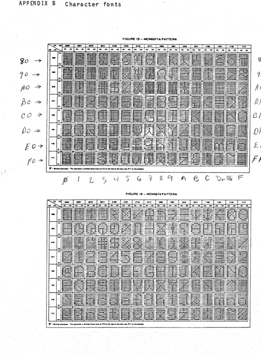
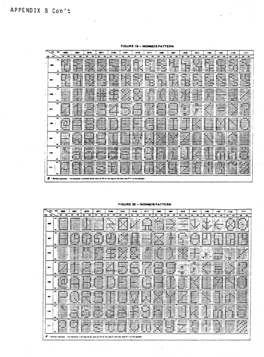
C. VDD bus for the character generating ROM IC36(6571-4). Measure +12V:t. 5% at the junction of R20/C29.
D. VBB bus for IC37: Measure -3V + 10% at the left hand lead of Dl. (This is. the only negative voltage •. )
5.1.2 If power bus shorts are suSpected, ohmmeter verification in-.volves considerations of the polarity of the test leads. The board
will not suffer from checks where the ohmmeter leads apply the polarity expected from the power supply and an open circuit voltage not exceed-ing the power supply value. The non-linearity of the load prevents us from predicting wha.t an unknown ohmmeter will read on a normal
board, but readings below an ohm mean that you should look for a short or an inverted IC. Reverse polarity from ohmmeter leads can be damag-ing'un1ess the current is limited to low values. Most series-connected 50 micro-amp movement VOM's are safe when only the 1.5 vol t battery is used on the scale selected.
5.2 Signal tracing
Unsolder the right end of the 100 ohm Rl (junction with pins 2, 4, 6, of IC31 ---- 7407) and attach a clip lead to the free end of the resistor for use as a scope probe. {Keeping a wire in the hole for the right end of R18 makes an easy way to remake the "normal" connection with
.. the cli.p lead .• )
PolyMorphic Systems
VTI
P. 35than 0.1 V. This produces DC levels at the 2N5449 emitter of about 2V normally (average. of normal waveform) and near 4V with an open test lead. 27% of these values should be found on the cable to the CRT. (If you have D.C. coupled into your CRT video, check that your design is proper for these values.)
Those' users owning oscilloscopes probably have sufficient technical background to interpret the following discussion into equiva-lent scope presentations. This discussion assumes that the only signal tracing display available is the TV or CRT intended for computer
display use. Therefore, the first checks are that the output stage is functioning and that its responses are visible on the CRT. If NOGO on these, check your cable and CRT input arrangement.
5.2.1 Video interface
Grounding the probe lead should pull the output emi~ter down to around a volt, and opening it should give a rise to around 4V. This transition should couple through the AC coupling to your CRT and be apparent as momentary brightening as the lead opens.
5.2.2 Localizing on the video path
If logic levels applied to the clip lead are modulating the dis-play brightness, but you are having to troubleshoot, let us consider what is missing. If, in the "normal" connection (i.e.: lead clipped to where should be soldered), there is an array of bright and dark spots on the display, chances are that video is being generated and that you will be chasing sync or blanking troubles. With only video coming through, most eRTs will at least partially sync on the video itself, and patient tinkering with the sync controls on the display and the two pots on the video board should give at least some torn-up version of what is trying to be a display. If you have sophisticated your power-up
de-PolyMorphic Systems VTI P. 36
rived from that clock. (The board is testable with nothing more than pro'Per'power supplies a'nd' a'clockfor' i'nputs.)
No video pattern? let us see if it is shifting out of the register IC35-6(8274) (pin 6 of rC35). Got it? Then the path through IC3l is not passing it. Check for it at the input pin 9 and output pin 8 of IC3l. Following the path should reveal a gap in Signal pas-sage that is correctable. This is the concept of Signal tracing that will be assumed throughout the remaining discussion .
.
No video shifting out of IC35-6? Well~ is there data on the input pins to be loaded for shifting or a load signal to load it -or a dot clocking to shift it out?
First the dot clock on IC35-9(8274): This should show as a raster full of tiny white dots. Depending on the setting of the
"width"pot~ there should be from 100 or so to almost 900 on each
raster sweep, but several factors influence this, Sync and blanking, if they are working, keep many dots out of the visible area. Also, the bankwidth of this setup may not permit you to discern dots at the higher frequency settings of the dot clock. Best to view this at the minimum frequency (ccw) setting of the "width" pot (pot at top left). Do not bother counting dots. Their presence is all that is necessary to show register shift clocking input. Since this signal is negative true,
a brighter presentation may' be found at the inverted form on IC30-8(74lS00). Absence'of sync should not prevent this display from being recognizable.
PolyMorphic Systems
VTI
P. 37Assuming that shift (dot) clocking and its subcount, EOC load clocking, are available, is there video data on the input pins to be loaded? Each of pins 1 through 5, and 11 through 14 should show a screen pattern of white and dark states as wide as the distance be-tween the vertical bars seen on pins carrying the EOC or shift load-ing pulses. So too should input and output pins of the MUX's IC33 and IC36(74LS157). Al~o the outputs ROM IC37 (6571) and the graphics generators IC38 and IC39 (74150).
The patterns associated with outputs from 1C38 and IC39 (74150) have a right to change every 5 sweeps. At the IC39 (74273) inputs to the display generators IC37, 38, and 39, (6571) however, the sweep patterns should not change more frequently than every fif-teenth sweep. These last patterns show what the memory is requesting for each character position of ten dots by fifteen sweeps. Counting these dimens ions is generally not necessary. Merely nothi ng that the fineness of detail is less at the input to generators than at the out-put is usually sufficient for trouble localizing.
The screen pattern for any significant bit input to the genera-tors should be traceable back through corresponding pins of the sampling latch IC40 (74273) to the same significant bit of the internal data bus. But remember, the nth character in memory is held in the latch until an EOC pulse strobes the latch and increments the memory address. If sync and clocking are at work to keep the display pattern straightened up, any lack of correspondence of the patterns up the path can be discerned. Without sync, it may take both a photographic memory and a lot of luck but the chances are that you would not be needing that level of de-tailed trouble-shooting without sync, anyway.
PolyMorphic Systems VTI P. 38 the MSB is a one in the RAM. Correspondingly, the display probe on IC33-1(74157) will show which memory. locations contain graphics or non-graphics characters. An MSB in memory is inverted in the latch to select graphics.
5.2.3 Localizing on the EOC (end of character) path
If you had dot clock input to shift register IC35-9(8274) but no strobe (IC35-7) to load the register, you will want to check back to where the EOC is generated by counting every tenth dot in ICl4. I~ fact, failure of IC30 (74LSOO) or other problems can permit it to count by other than ten, with some weird results in displays. Clock dots are discernible at the input IC13-2. Slowing the dot clock (CCW on the "width" pot) makes these countable by eye. A piece of paper on the screen or a millimeter scale may help. Sync helps here but should not be necessary to array the pattern of dots into vertical bars. IC13-14 (74161) has half as many vertical bars but of double ~.
width. Pin 13 has narrow vertical white bars equal to twice the width of the bars on pin 14. The total pattern of pin 13 is repetitions of
black, white, black, white, white vertical bars. The last two whites show as a double width white as the carry preloads a 6 into this 4 bit binary counter. This preload makes it produce a carry every tenth dot_ If pin 13 looks right, chances are that all the rest is okay.
The tenth dot carryon ICl3-15 is the EOC (end of character) signal. It should appear at the input to the symbol counter ICI6-l3. An inverse (negative true) of this pattern should be found as loading signals n latch IC40-11 (74273) and shift register IC35-9. Of course, if there is no dot clock, none of this paragraph is working properly. On the other hand, presence of dots anywhere does not leave much room for problems in the dot clock.
5.2.4 Localizing on the dot clock path
PolyMorphic Systems
VTI
P. 39NAND gate in IC30(74LSOO), or some such, because the clock is present at the other end of these places. If neither is present (and of course no EOC signals), then look for dots at the clock IC29-7 (745124).
Using a voltmeter, check its "width" pot for the ability to vary IC29-2 from zero to 5 volts. Check also for the enabling portion of the horizontal blanking signal on IC29-6. This may be hard to see as a broad vertical bar in the presence of strong horizontal sync, but if desyncing gives you a torn version of it, it is probably okay. A volt-meter reading on IC29-6 of 5 VDC would be a continuous disable signal. Under proper conditions, the average of the horizontal blanking wave-form reads typically 0.9 to 2.3 VDC on a meter at IC29-6. The value is under control of the IIpOS" pot which varies the time delay (and thus the average DC value) the the blanking monostab1e.
5.2.5 Localizing on the horizontal blanking path
Under the most ideal conditions of sync and blanking, events occurring during flyback, retrace, or blanking should not be visible. Note that opening R19 does not open the composite sync path at IC31-10 (7407). Therefore, sync, if operating; will reach the CRT sync cir-cuits - regardless of what ;s done with the probe lead. Remember, even without sync working, most CRT's or TV's will find in many of the test signals something repetitious enough to sync on. There is usually a way to view sync-hidden signals by misadjusting the horizontal hold con-trol of the CRT to force a "tear" in the picture. Then if the sweep rate is calibrated in time units, the signal can be measured in the torn portion. An example of this is horizontal blanking. Forcing a torn but stable pattern reveals a dark space in each sweep when look-ing at IC29-6 (745124). Varylook-ing the "pOS" pot changes the width of the space.
PolyMorphics Systems
VTI
P. 40change it, it is working. Perhaps easier to see is its inverse. -a logic high on IC34-5 (7'4123). For this, yousho.uldnot hav-e to force the tear. Horizontal blanking that is high logic will appear as a bright verticaT bar at one or both sides depending on where the CRT is syncing. For most IC's, if Q is 'working,
Q
probably is also. Take the easiest way down the localizing path first and back up to the harder ones only when necessary.No horizontal blanking? How about the horizontal sync which triggers the IC34 monostable multi-vibrator to stretch the sync into a wider blanking? The carry-out of counter ICl-15 (74161) should have its inverse on IC34-9 (74123). This is a
412
microsecond pulse every 5~ microseconds.Actual horizontal sync is the same width, but 4~ microseconds later, and can be seen on IC3-13 (74lS02). Its inverse 'is one IC3-1 but is also mixed with vertical sync. Observation af a
once-per-sweep, narrow vertical bar is probably sufficient to el iminate further details up this path,. but if things are not clearing up, you may
want to calibrate time as in 5.3.1.
If these are NOGO, is the system clock on edge pin 49 and is it reaching IC2-1 (74161)?
You can use your piece of paper or plastic millimeter scale to ratio the, distance between leading edges of the bars. However, if the vertical bar pattern on IC2-l4 is repetitions of black, white, black, white, black, white, black, white, white, then the binary 7 is apparently pre10ading on every carry and division is probably okay.
(Compare this with the discussion of the dot counter in 5.2.3.) Counting bars will only tell you how many of the 58~ micro-seconds per sweep are visible on your. CRT and usually does not contrib-ute to trouble analysis.
IC2-2 has an inverted form of ICl-15 showing a dark bar every '~:mi;c::roseconds,,_but divisi:on by 13 is difficult to ratio unlessYQu
-PolyMorphics Systems VT1 P. 41
shrinking the picture sufficiently to see both ends of the sweep. But then -- if any of 1C2-11 (74LS138), 1C2-13 (74161), lC2-15, or lC3-13 (74LS138) have an observable once-per-sweep bar, horizontal sync seems to be doing its job.
5.2.6 Sweep and symbol related counter\patterns:
Verification of sweep counter test patterns is difficult in the absence of horizontal sync. Since the sweep counter is count-ing the carries from the same counter that generates horizontal sync, the presence of one signal without the other would indicate that the integrity of any missing path should be reestablished before proceed-ing. The clocking input lC15-l (74393) is a once-per-sweep pulse which may not be in the visible portion of the sweep unless a tear is forced in the horizontal hold. All other patterns are stretched by the sweep into horizontal bar patterns with the exception of the reset lC15-2. The reset is like the clock on lC15-1 except a) it occurs every 15th sweep; b) it is a 4~ microsecond darkening instead of a brightening; and c) it occurs 4~ microseconds later (to the
right) on the sc~een. It is therefore probably visible only under torn conditions.
Correct patterns for pins 3, 4, 5, and 6 of lC15 can be inferred from the timing diagrams. A quick check of proper operations and
counting by fifteen can be made on pin 4. The pattern for lC16-3 is: every other pair of sweeps is white (2nd, 4th, and 6th pairs) followed by the single white 15th sweep during which the counter is reset. Symbol lines are perhaps better defined by the double black sweeps visible on lC15-13. These occur because of the adjacency of the first and last sweeps, which are both dark, while all even numbered sweeps including those during retrace are bright.
As further subcounting is done in the line counter, lC15-11 _shows every other 1 ins (group of 15 sweeps) as dark or brtght.
PolyMorphic Systems VTI P. 42 caused in each sweep. This can permit an alternate form of checking division by 15 (sweeps per line) in the sweep counter.
The MSB in the line count is white in the bottom half of the display. After the bottom bright. trace of IC15-8, IC2-9 shows the bright inverse of 8 sweeps of vertical blanking at the bottom of the screen and the later sweeps normally hidden by the vertical blanking at the top of the screen.
Patterns for the symbol counter IC16 (74394) can be directly inferred from the theory discussion and the pin outs of the
74393. The EOC pulses described in a.2.3 are seen as a vertical bar per symbol space on IC16-l3. Successive divisions by 2 on pins 11, 10, 9, 8, 3, 4, and (if 64 symbol option, pin 5) are seen as fewer, wider bars. Reset will appear on pins 12 and 2 as it does at IC34-5. (Refer to Section a.2.5.)
The functions of IC12 (74138) and IC34 (74l23) are not directly observable in the presence of sync. If no sync at all is reaching the raster, normal operation of IC34-l3 can be noted as small (on the order of 30 nanoseconds) specks scattered in regular
fashion throughout the raster. If sync is working operation may be
,
inferred by noting rapid regular jumping of vertical sync when IC34-l ,is held to ground.
The combination of IC34b and IC12 can be checked by grounding pins 4 and 5 ~f IC3. Under this condition, the normal output con-nection to the display will show repetitions of seven darkened sweeps of vertical blank followed by thirty visible sweeps of re-trace allowance. Also, placement of the test clip on IC12-l2 will show continuous repetitions of seven dark sweeps, eight white sweeps, seven dark, fifteen white.
PolyMorphic Systems VTI P. 43 Normal events on the dot blank flip-flops IC32-2, 4, 5, and 8 (74LS74) produce vertical bars on a once per sweep basis. Posi-tion and width of the bars is variable by both IIpOSIl and IIwidthll
pots. The waveform average of these waveforms read on a DC
meter will also vary under control of these pots. If sync prevents visual observation of these pulses, DC voltage variations by the pots can be taken as proof that the variable width dot blank is reach-ing the right places.
5.3 Diagnostic aids
Viewing the display in normal conditions gives information on where to start troubleshooting. A blank screen directs attention
to sections 3.2.1 through 3.2.5, which look for dynamically changing patterns originating in a sequentially scanned memory, being trans-lated in the ROM's and being shifted out of the register. In the pro-cess, dot clocking and EOC signals are investigated as necessary.
A dynamic but useless display in normal conditions, on the other hand, directs attention to the ~ubcounters and decoders which control memory address, the blanking of the display borders, and the orderliness of symbol element display.
PolyMorphic Systems VTI P. 44
5 .. 3.1 Timecalibration
In verifying the timing diagrams related to horizontal sweep rates, the·4Ja mi.crosecond wide bars on ICl-14(74l6l) give a quick idea of how much of the timing diagram will show on your TV. A 50 microsecond block is indicated on most of the timing diagrams, but a typical TV might show five white and give black bars on ICl-14 for a total display of 45 microseconds. Remember also that horizontal sync may permisSibly vary widely, so that your picture may start at a different point in comparison to the arbitrary marks on the diagrams.
Calibration of the vertical dimension or vertical sweep time base is perhaps easiest by looking at IC15-3 (74393). The leading edges (measuring top to bottom) of the groups of white sweeps are 15 sweeps or 877 microseconds apart. A 16 line (240 sweep) visible raster is 14.04 milliseconds, and vertical sync recurs every 277 sweeps or 16.205 milliseconds.
PolyMorphic Systems VTI P. 45
6. VTI theory of operation and block diagrams
The principal functional blocks which form the video termi-nal interface are shown in figure 8-1. The on-board memory is con-nected in parallel with the keyboard input port to an array of
I/O buffers driving the Altair data bus. This allows the transfer of information between the memory and the data bus or between
the keyboard and the data bus. These data transfers are controlled by logic driven from the address and control lines. For example, the processor can read or write a location in memory just as it would with any main memory -- it outputs the memory address (16 bits) while signaling a read or a wri'te by the state of the control bus. The six most significant address bits are compared to the jumper selected bits (as discussed in section 22). If these bits match, then the remaining 10 address bits are gated through to
select the memory location. At this time the appropriate bus drivers are enabled to read from or write into memory, according to the
control bus command. If the control bus signals neither a memory read nor a memory write, but rather an input instruction, then the keyboard buffer is enabled instead of the memory. Note that the in-put port address (8 bits) is the same as the most significant byte of the 16 bit memory address. When the processor is not accessing the video terminal, interfacing with an input of memory instruction then the video refresh circuitry takes control of the memory. The memory locations are scanned by the control and sync generator, with the memory data being fed into a character ROM. This read-only memory stores the vi deo dot pattern of each ASCI I character4• The
DATA IN BUS DATA OUT BUS CONTROL BUS ADDRESS BUS
<;
PolyMorphic Systems VTI P. 46
shift register and shifted out serially. This signal is then mixed with the video sync signals to form the composite video output.
r--l/l
KEYBOARD AK
N
BUFFER"
11)'
t
a::
w II. II. ::l
CD .... ALPHANUMERIC PARALLEL'
0 512 x 8 TO SERIAL
::: ~ OR ~ ANO -~ CONVERSION
GRAPHICS
1024 x 8 ./ CHARACTER
r---v
ANDMEMORY SYNC
C=) / GENERATOR MIXER
v
J
...A
.,.
I
'--r---t/).0
11
II
j~
..
I
-"., 1/0 CONTROL AND
CONTROL
-v ' LOGIC
-
SYNC GENERATOR'r
A more detailed view of the board circuitry is shown in the schematic diagram at the end of this volume. We are now going tp exam; ne the board in some detail to see how it performs its various functions. The level of complexity is fairly high; not all readers will find it useful.
data bus. data
(VTI)
bus.
Look at the schemati c and note that all the on-board memory, latches, and bus
This bus can be bus. We will be data bus as the
drivers are connected to a common on-board data driven by, or can drive, the S-100
referring to the video terminal interface
on-board bus, and the S-lOO bus as the external
Another point of terminology is sweep vs line. Each character on the TV "screen consists' of a selection of dots in a dot matrix that is seven dots wide by nine high, embedded in a field of ten by fif-teen dots (to provide space between characters). So the TV picture tUDe 'must: sweep' fi f'feentimes ,.ta produce one"line' 'of characters.
I KEYBOARD INPUT
-PolyMorphic Systems VTI P. 47 The following discussion applies equally to the 32-character line and the 64-character line options.
6.2 Symbol generation
Wi th a low on the OE (output enable) 1 i ne from, I C9 to the RAM (random access memory) pins 9, the addressed portion of the RAM is continuously sent to the internal data bus in the refresh mode. Eight-bit display data on the internal data bus is sampled and held in the latch IC40 whenever there is coincidence (in IC30) of a dot pulse from the dot clock IC29 and an "end of character II
(EOC) signal (tenth dot carry) from the "dot counter II IC13. In the
absence of a one in the MSB (most significant bit) from the latch, MUX's (multiplexors) lC33 and IC36 pass the seven-dot conversion pattern of this display data from the character-generating ROM (read-only memory) IC37 to the 1east significant bits of the output
shift register IC35. When the eighth bit specifies that graphics are being generated, these MUX's switch to select all ten bits of the data for the shift register from IC38 and IC39. IC37 and IC38 are, in effect, the graphics generation ROM.
In the case of non-graphics characters, the first three dots of every character space are always low to create spaces between letters. Note that, while the latched data for the nth character position of the sweep is identical for fifteen consecutive sweeps, the ROM output may vary in each sweep, according to the additional addressing from the sweep counter half of IC15. The sweep counter is self-resetting after every fifteenth sweep, and this resetting
action is accumulated in the line counter half of IC15.
In similar fashion, the dot counter- IC13 is self-resetting every tenth dot, and its output is accumulated in the symbol counter IC16. The combination of line and symbol counter outputs determine the address of each individual character stored in the memory
PolyMorphic Systems VTI P. 48
sweep, and line) are reset by appropriate relationships to the hori-zontal and vertical sync (respe.ctively) of the TV ras.ter, the low-est memory address will always contain the record for the top left corner of the TV' display. Corresponding relationships are similarly maintained between other addresses in memory and positions in the display field.
6.3 Raster and timing
Horizontal sync, vertical sync, and vertical blanking are timed by subcounting the absolute frequency system clock. Hori-zontal blanking is initiated at the'end of sweep by subcounting the variable frequency dot clock IC29, and blanking is maintained by a variable-duration one-shot IC34. Varying the IJpOS" pot changes the one-shot delay and thus the position in the next sweep where the display is again unblanked. ' Varying the dot clock fre,quency ("width" pot) changes the rapidity with which the full line char-acter count ,will accumulate to initiate horizontal blanking and therefore the distance across the screen that is used for display.
The system clock is divided by nine in ICl and again by thir-teen or fourthir-teen in IC2. A carryon exit from the highest (16th) state (all fou~ output bits
=
1, or binary 15) is used to preload a binary 3 into the same IC2 so that it may again divide by 13 or 14. This binary 3 at the IC2 outputs will therefore last for one-thirteenth or fourteenth of the period between carries and is passed through IC3a to the TV for horizontal sync. The same carry triggers the horizontal blanking one-shot. The carry is also used to clock the 4-bit binary sweep counter (IC15a) which is used both to address the character generation ROM and to signa] the line counter ICI5b every fifteen sweeps that a new display line is being addressed.When 16 line counts (16 X 15
=
240sw~eps) have accumulated.
PolyMorphic Systems
VTI
P. 49IC4 also enables the 1 of 8 decoder IC12. After eight blanked sweeps have been counted by the sweep counter IC15, Pin 14 of IC12 will go low, producing a vertical sync pulse.
This vertical sync lasts the seven more 'lines until IC15a resets itself and advances the line counter. IC3 ANDs this vertical sync with the horizontal sync carry, so that the interruptions in the wide vertical sync pulse maintain horizontal sync,
Further subcounts fo the sweep and advances of the line counter accumulate in IC15 until IC12 decodes the 37th blanked sweep to trigger the pulse stretcher IC34. (Line counter
=
2 and sweep counter - 7.) IC34 is a very short duration one-shot which termi-nates the vertical bl.anking (disabling IC12) and also resets the sweep and line counters for top of the page addressing. The subsequent termination of horizontal blanking has the character counter IC16 reset to prepare all addressing from the top left of page as des-cribed below.6.4 Symbol and raster synchronization
Termination of the horizontal blanking one-shot IC34a re-enables the dot clock oscillator IC29a but does not unblank the screen. At this time, symbol count addresses are set to zero, but the data latch IC40 contains unrelated data sampled with some pre-vious address. Similarly, the shift register rC35 contains old data. The screen has been darkened by the dot blank flip-flops of
IC32 which have been held set by the horizontal blanking. The sym-bol counter IC16 MSB is presenting a zero to the 0 input of flip-flop IC32, however. After the first ten dots from the dot clock, the shift register (which is shift-clocked by dots) is emptied and the EOC (end-of-character) signal from the dot counter IC13 sends load! signals 'gated} through- 1 G30 to both 'the!" data- 1 atch andc the
shi ft regi ster. Since propaga ti on time through the ROM's and MUX I S
PolyMorphic Systems VTI P. 50 register is loaded with different but still useless data. The same end;.of-cha.rac.ter ,pulses., however ,.have advanced. the symbol address in lC16 by 1 and have also propagated the zero at the input of the first 0 Blk (dot, blank) flip-flop to the second flip-flop. The ROM and MUX paths present valid first symbol data to the shift reg-ister so that the second OEC pulse loads first symbol dots into the shift register and second symbol data into the latch.' They also propagate the zero through the second dot blank flip-flop so that the screen is unblanked for the first symbol data shifted out of the register by the subsequent ten dots.
When the 32nd (or 64th) end-of-character pulse accumulated in the character counter, it loads the data 'latch with the 32nd (or 64th) character and the register with the next-to-last charac-ter. Simultaneously, the MSB of the symbol counter presents a 1 to the dot blank flip-flops, and the next 20 dots shift the last
two symbols out to the video, and. the 1 through the flip-flops to (. blank the screen in the 33rd (or 65th) character position. The dot clock runs, and the dot and symbol counters keep accumulating, but the MSB of the character counter maintains its 1 input to the dot blank flip-flops until either double the number of symbols is counted or, as normally, horizontal sync and horizontal blanking occur to stop the dot clock, reset the symbol counter, and reaffirm the dot blank.
Clocked by the sweep counter reset, the line counter will increment every fifteen sweeps until the vertical blanking process described above resets the MSB's of the addressing. system.
6.5 External bus and keyboard i nterfaci ng
PolyMorphic Systems VTI
In the switched condition, RAM address is determined by the ten LSB's on the external address bus instead of by the combina-tion of the line and sumbo1 counters used in the display refresh mode. The BS- strobe also enables the line drivers that put internal data bus information onto the external data bus. If
P •. 51
INP+ (pin 46) is also true, keyboard data latched in IC41 will be sent to the CPU via the line drivers. The MEMR+ singnal, if present,
•
similarly enables the memory output to the on-board bus. If MWR+ (pin 68) is high with BS-, the line receivers are enabled by IC71s
PolyMorphic Systems VTI P. 52
7. Software
7.1 Video Typewriter:
Both the input to and the output from a computer is ordin-arily a stri ng of characters, whether it be characters typed in from a typewriter-like keyboard or output from the computer to a
printer. Not all of these IIcharacters,1I however, strictly corres-pond to a printed symbol, like a letter. Consider the output to a pri nter. Some IIcharactersll will cause the pri nter to perform some
function other than a keystrike -- such as carriage return or back-space.
The VTI is essentially a block of memory, and at the hard-ware level does not distinguish between characters and other func-tions. ~lithout an intervening program, the VTI would send a II car-riage returnll on to the screen or a symbol, rather than returning
to the beginning of the line.
We include here a program that accepts a string of ASCII characters and causes them to appear on the screen exactly as the characters would be printed by a printer. IICarriage returnll causes
the cursor to return to the beginner of the line, IIline feedll causes
it to move down one line, and so forth.
The program includes a keyboard input routine, which puts the characters you type on the keyboard directly onto the screen, with proper carriage return, line feed, and other functions. Load the program as· written. To use the computer as a "TV typewriter,1I connect the keyboard to the parallel input port provided on the video board.
This program when executed at address ~000 causes char-acters ,typed .. in. at, the, keyboard ,to' appear on the screen· as they would be printed by a printer.*
The--principa 1 useful ness of the program is to ; nterpret the.. output of ano.ther,program wh-ichwou,:j d ord; nar; ly be sent'· on to a printer, so as to put the appropriate visual display on the screen.
• 0
PolyMorphic Systems VTI P. 53
Programs ordinarily send a character from the accumulator to a serial output port in response to the instruction 1I0utll. The fol-low.ing program includes a subroutine called 1I0ut,1I located at address
ID00H. When called, this subroutine interprets the character in the accumulator as required to put it on the screen. In convert-ing a program to run with the VTI, substitute ilcal1 out" for the output instruction.
VIDEO TERMINAL SOFTWARE COMMAND SUMMARY
Control Character Function
Cursor Controls
H R L U
o
E X
Home Cursor Cursor Right Cursor Left Cursor
!LP
Cursor Down Erase Screen delete characterMode Commands
I T
F
N S P
Insert/delete mode set Text (reset I/O mode) auto line Feed mode set
Normal TTY-(reset AlF mode) Scroll mode set
Page (reset scroll mode)
line feed advances cursor one line, exception last line in' sCioll mode; then cursor fixed, and page scrol·ls.
PolyMorphic Systems
VTI
P. 547.2 Graphics
The PolyMorphic VTI includes full graphics capability. Any or all character locations on the screen can be used in a graphics display.
When a screen location is part of a graphics display, it is subdivided into six parts, thus:
:/ !
(NOTE: Graphics display uses the entire screen location, includinq the border area that is kept dark to provide space around other characters). Each of the six IIcellsll of the screen location
corresponds to one bit in the byte stored in the screen location. The
IIzero bitll corresponds to cell 0, etc.:
7 6 5
0
Graphics:
101
XI
selects character7 6
0
ASCII :
11
I
selects characterI
X=don't care.,. may be 1 or
0
o
is 1I0nli or IIbriqht,1I 1 "off" or "dark." Thus~ storingPolyMorphic Systems VTI P. 55 In the appendix is a chart of all 64 possible graphics char-acters, with their" associated hex values.
The foll owing "game" program, called LIFE, ori gi na 11y i n-vented by John Conway and popularized by Martin Gardiner in his "Mathematical Games" Section of Scientific American in 1970, illus-trates the power of the, graphi cs capabi 1 i ty.
LIFE depicts the birth, growth, and death of a culture of cells. When a cell has one neighbor or no neighbors in the eight cells adjacent to it, it dies of loneliness. When it has four or more neighoors in the eight adjacent cells, it dies of overcrowding.
It survives neighbors. for as long
into the next generation whenever it has two or three So a cell may live for just one generation, or may live as the culture lives (or anything in
.
betwe~n). A cell is born whenever an empty cell location has exactly three neighbors. (Cells are trisexual.)The game begins with an initial entry, or Divine Creation, of a seed organism (group of cells). The initial entry can be as simple or complex as you like. The life cycle of the resulting culture arises entirely from the nature of the initial entry given the rules of LIFE.
The following program executes the rules of LIFE on the video screen in graphics. Load both programs at the addresses indicated. Execute the screen clearing routine at ~F0~. If your system has a stack area al ready all ocated, then you need not set the stack poi nter.
PolyMorphic Systems VTI P. 56
Video Typewriter Routine SToRt AT" .3
Mnemonic Hexidecimal Address 8e0~ 91?n30 0(100 9(100 0('f00 BetOO 0(100 0(100 oeee 9000 Op Code
"l~~0e 21 e0 80 9'303 22 FC lC 9'!t'36 70
9007 32 B0eA 21 90eD E5
FE lC 11 08
0eOE Cl 65 10
(fetll FB
0012 C3 11 00 0015 e0lS 903A ,jet3C ,)et3E 003F 0042 78 0041 C9
DB 88 F6 813 F6 80 47
CO 00 10
13044 iD00 1003 1D';t4 lDe7 10'3B 1Det9
2A FC lC EB
21 00' 88 19
47
3A FF lC 1D':-tC 77
1D00 78 10'lE FE :38
_1010 CA SC 10
1Dll FE ~:5
lD15 CA 65 10
1018 FE 92
101ft CA 74 10
1010 FE 95
101F CA 7C 10 -1D22 FE
l