Three-dimensional Irregular Tree Modeling For
Special Virtual Environments
Ling Xu
Abstract—Computer synthesized three-dimensional (3D) tree models often appear in virtual environments of 3D movies and games. They act as decorations or functional components, making the virtual worlds more realistic. Although regular tree shapes are commonplace, irregular tree shapes with highly crooked branches are also needed in some special virtual scenes. This paper presents a procedural method for 3D irregular trees modeling. The whole tree structure is generated in a 3D weighted graph and tree branches are least-cost paths connect-ing selected points. The scale of branch irregularity is controlled via a mechanism of setting the edge weights. The resulting models have realistic tree characteristics, and also demonstrate the desired features of irregularity and heterogeneity.
Index Terms—virtual environment, tree modeling, 3D, geom-etry synthesis.
I. INTRODUCTION
V
IRTUAL environments play an important role in computer-generated movies and games. Natural phe-nomena such as trees, clouds, rivers, and mountains are commonly seen in the synthesized virtual worlds. However, it is a challenging task to create the models for these natural objects, due to their complicated structures and rich varia-tions. Three-dimensional tree modeling is a typical example. Trees have a hierarchical structure with different scales of branches such as the trunk, primary branches, and twigs. The global features such as the architecture and the distribution of branches, and the detail features such as branch shapes and gaps between branch clusters, vary much among different tree species. It is tedious and time-consuming to create a 3D tree by depicting these features manually.In order to release the burden on computer artists, there are many automatic or semi-automatic methods proposed for 3D tree modeling and capable of generating realistic models. However, most methods are focused on modeling regular trees that have a symmetric global shape, normal branch-ing structures, and homogeneous distribution of branches. Creating irregular tree models has been rarely explored. Irregular tree shapes can be some real trees, for example, the Japanese maple tree as shown in the left of Figure 1. It has twisted crooked branches, distinct from the elm tree on its right side which has a regular structure and smooth branches. Irregular tree shapes can also be those fictitious in special virtual scenes for the purpose of building a scary or weird environment. For example, in the game “Halloween Runner”(Figure 2 left) and the movie “Tales of Halloween” (Figure 2 right) , the trees have spooky branches, demonstrating a highly irregular structure. Despite the great
Manuscript received July 23, 2018; revised Aug 9, 2018. This work was supported in part by the Organized Research and Creative Activities (ORCA) Program of University of Houston-Downtown.
L. Xu is with the Department of Computer Science and Engineering Technology, University of Houston - Downtown, Houston, TX, 77002 USA (e-mail: [email protected]).
[image:1.595.306.547.210.334.2]needs of irregular tree models in many applications, previous tree modeling methods can hardly generate these structures effectively.
Fig. 1. Left: a Japanese maple tree with crooked branches; right: an elm tree that has smooth branches spreading out. Images from Flickr.com.
Fig. 2. Virtual trees in game and movie scenes. Images from Flickr.com.
In this paper, we propose an automatic method to address the above problem. The method is built on the tree modeling work using path planning [1], [2] and guiding vectors in-troduced by Xu and Mould [3]. The basic idea is to build a weighted 3D graph, then get a set of least-cost paths between selected nodes in the graph. Each path is a tree branch and the whole collection of paths form a tree structure. The general path shapes can be controlled via guiding vectors, i.e. vectors at each graph node used to set edge weights. In order to create irregular crooked paths, we propose a novel method: the branch growth patterns can be simulated by varying guiding vectors through periodic rotations. This method can effectively create realistic tree models with different scales of irregular features.
This paper makes the following main contributions. 1) It presents a method of varying guiding vectors. The
[image:1.595.306.547.385.514.2]segments, the general tree architecture is still regular. It can hardly achieve large-scale branch irregularity. The method proposed in this paper can effectively control the large scale and intermediate-scale irregular features; the resulting tree structures are distinct from the previous models.
2) The work presented in this paper contributes experi-ence for special 3D scene synthesis, which has been rarely explored. With the fast development of computer techniques in 3D games and movies, the modeling of special scenes requires more effective options and fast methods. Our work contributes an automatic method and valuable experience in this regime.
The paper is organized as follows. Following the intro-duction, in the section of background we will review related methods in tree modeling. The algorithm will be introduced next. Results will be given and discussed in section 4. The last section includes a conclusion and proposes the future work.
II. BACKGROUND
Tree modeling has a long history in computer graphics applications. Numerous methods have been proposed since the earliest tree synthesis in the 1980s. Scanning methods are one category of them. In order to create a virtual tree model, scanning methods [6], [7], [8] use a 3D scanner to sample points on the surface of a tree and gather data including position, color, and texture of each point. The point data will then be used to reconstruct a 3D tree model in computer. Because the data comes from real-world measurements, scanning can produce high quality tree models with accurate description of tree features. However, most scanning methods have a common problem – the collection of data is affected by the occlusion of tree branches and leaves. To address this problem, extra pre-processing and post-processing work is required in order to remove noises and recover the missing data. In addition, the availability of scanning devices restricts wide uses of the technique among regular users. It is also an obstacle for novice users to operate the devices [9] to get satisfactory data. It is worth attentions that scanning is good at reconstructing a 3D model based on a real tree example, but for some tasks such as modeling a fictitious irregular tree, it is not easy to find a corresponding tree example in the natural world.
Another category of commonly used tree modeling meth-ods is procedural methmeth-ods. Procedural methmeth-ods [10], [11] focus on algorithms and parameters, having more freedom to create tree models without restrictions from hardware. They can create complex details of tree structures via designing algorithms and setting parameters. The strength of procedural methods is automatic and flexible control of resulting struc-tures by varying parameters. A famous example of procedural methods is L-systems. The basic idea of L-systems is based on rewriting rules composed of strings of symbols; each sym-bol can be interpreted as a geometric shape such a segment of tree branch. Through some iterations of rewriting, the final string decides the resulting tree structure. A challenge for early L-systems [12], [13] is to relate the specific target tree structure with the abstract production rules. Later L-systems [14] use sketches to guide the rewriting process,
partly solve the problem, but at the same time depend greatly on user’s intervention.
[image:2.595.358.494.221.347.2]Biologicbased methods such as space colonization al-gorithm [15] and self-organizing method [16] generate tree models based on botanical rules. The resulting tree models are convincing and realistic, due to the biologically plausi-ble process for tree development. Biological-based methods are good at generating realistic small-scale irregularities in individual branches and global branching tree architecture, but controlling the tree features especially large-scale branch irregularities using the unfamiliar botanical meaningful pa-rameters is not easy.
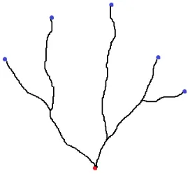
Fig. 3. A basic branching structure generated by the method of path planning.
The method introduced in this paper is built on the earlier algorithms of path planning [1], [2], [3]. Path planning is the problem of finding the least-cost paths in a weighted graph [17]. By selecting a root node and a few endpoint nodes in the graph manually or automatically, the least-cost (or shortest) paths connecting the root node and the endpoint nodes form a branching tree-like structure. The idea is demonstrated in Figure 3, where the black least-cost paths connect the red root point and the blue endpoint nodes. In order to make the coarse branching structure resemble real trees, Xu and Mould proposed the method of guiding vectors [3]. In this method, a number of nodes are scattered in a specified 3D volume, such as a cube. Edges connect near nodes. Each node has a vector named guiding vector, used to set the weights of outgoing edges from the node: the weight has a minimum when the guiding vector and the edge direction coincide and a maximum when they are opposite. Since least-cost paths tend to take cheap edges, through specifying the directions of guiding vectors, we can control the shape of least-cost paths. Figure 4 shows the influence of guiding vectors (red arrows) to the shape of a least-cost path: the path is pushed to bend and follow the flow of guiding vectors. Figure 5 shows a tree model created by rotating/bending the guiding vectors (initially in up direction) gradually outwards and downwards from the center. The left shows the basic structure from a few paths. By adding more endpoints in the vicinity of previous paths, we can get more complicated hierarchical tree structure as shown in the right.
Fig. 4. Top left: a graph with a guiding vector at each node; top right: guiding vector (red arrow) decides edge costs based on its deviation from the edge directions (blue arrows); lower left: a path from a graph without guiding vectors; lower right: a path from a graph with guiding vectors (red arrows). Lower figures from [3].
Fig. 5. Left: a basic branching structure generated by the method of guiding vectors; right: a tree with denser branches by adding more endpoints. Images from [3].
guiding vectors is generally smooth, leading to smooth branch shapes. This feature is plausible for regular trees, but not what we pursue in irregular tree structures. We are interested in creating tree models that have crooked branches, such as those appear in Figure 1 and 2. Another observation of the tree model from the method of guiding vectors is the generally evenly distributed branches. We expect a stylized tree structure with big gaps between primary branches, as what we can observe from the previously shown irregular trees. To address these problems, we propose a novel method of setting guiding vectors that can effectively create the above target features. More details are introduced next.
III. ALGORITHM
The algorithm introduced in this section focuses on the setting of guiding vectors, which is effective in controlling the branch shapes, especially large-scale and intermediate-scale crookedness. Before the introduction of this method, we first introduce the mechanism of setting guiding vectors. The setting of guiding vectors and weights of outgoing edges are done in concert with the path planning using Dijkstra’s algorithm [18]. The Dijkstra’s algorithm is an algorithm to compute the least-cost paths from a source
[image:3.595.57.278.333.447.2]node (i.e. the root node in our case) to other nodes in a weighted graph. The Dijkstra’s algorithm starts from the source node, whose guiding vector is initialized to the up direction. Subsequently its adjacent nodes (i.e. child nodes) are visited. Similarly, the visits of more nodes take place in a brushfire way spreading outward until all nodes in the graph are visited. At the same time, when a graph node is visited, its guiding vector is decided by a rotation at an angle αfrom its parent node’s guiding vector. The incremental rotations initiated from the source node to the other nodes decide a smooth flow of guiding vectors in the whole graph. As the result, the least-cost paths tend to follow the orientations of guiding vectors and form smooth shapes.
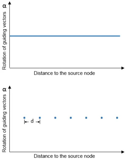
Fig. 6. Upper: the setting of guiding vectors in the method by Xu and Mould [3]; lower: the setting method proposed in this paper.
The idea proposed here is inspired from the observation of staircase shaped branches of Japanese maple trees (see Figure 1). Instead of setting guiding vectors in an incre-mental way, we rotate the guiding vectors periodically. The purpose is to keep guiding vectors constant within every short distance so that to make the resulting least-cost paths keep straight accordingly. Figure 6 shows two methods of setting guiding vectors. The upper is the method by Xu and Mould [3]: the rotation of guiding vectors increments with the distance to the source node. The lower shows our method: the rotation of guiding vectors only take place periodically at short distance intervals. This method provides controls via two parameters: distance intervaldand the rotation angleα. Next we discuss how to control the irregular features of the least-cost paths by varying them.
change its orientation – that is why the crooked shape is produced. Figure 7 shows the influence of d to resulting structures. From left to right,dis 5, 10, and 15. The branches demonstrate larger crooked shapes.
Fig. 7. From left to right, the structures obtained by setting the distance
dto 5, 10, and 15. In all three structures, the value ofαisπ/2.
Fig. 8. From left to right, the structures obtained by setting the rotation angleαtoπ/6,π/3, andπ/2. In all three structures, the value ofdis 10.
While the distance parameter daffect the scale of crooks appear in a branch, the parameter α is used to control the shape of crooks in branches. Smaller value of α means less rotation of guiding vectors, thus make the individual branch smoother and less irregular; on the contrary, guiding vectors rotated at greater α lead to greater changes of path orientations and more distinct crooks. This feature can be observed from the rightmost structure, which has the greatest rotation angleα. Figure 8 shows the above described features.
IV. RESULTS ANDDISCUSSION
The algorithm introduced above has been applied to create 3D tree models. In the following figures, we show a few 3D tree models, and also make side by side comparisons of our results with some results from previous methods. The evaluation of the results is based on visual inspection, which has been commonly used for evaluating tree modeling [12], [22], [14], [15], [2], [3]. Since the tree models are mainly used for entertainment purposes such as 3D movies and games, not for precise duplication or simulation, audiences appreciate the models rather than analyzing them from a scientific sense. There does not exist an objective function or standard for evaluating the quality of tree models [19], [20]. Although some researchers proposed precise measurements [21], [22] where a distance measure incorporates shape, geometry, and structure, these measurements are used to inspect the difference/similarity between two trees, not for evaluating the quality of a tree model. In order to make subjective visual inspection more substantial, in the following we describe the presence/absence of target features in the tree models, for the ease of evaluating the quality of results and the effectiveness of algorithms.
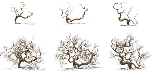
In Figure 9 we show a set of tree models with skeletons created by varyingd andα. From left to right, the top row shows the structures obtained withα= 90andd= 5,10,15
respectively. The right tree has the largest scale of crooks while the left tree has much finer crooked details in each branch. The lower row shows the finished tree models by adding more branches from more endpoints. The distribution of twigs and gaps make the trees convincing and realistic, demonstrating our desired irregular features.
[image:4.595.305.550.177.295.2]Fig. 9. Top row: three tree skeletons; lower row: trees with more branches.
Figure 10 shows a regular tree structure (left) from Xu and Mould’s method compared with the irregular tree model (right) from our proposed method. The left tree has multiple thick primary branches developed from a short trunk, all growing upwards. The right tree has two primary crooked branches: each has a few slimmer branches attached, forming a big gap between two clusters of branches. This feature is successful and just what we pursue.
Fig. 10. Left: a regular tree model from Xu and Mould’s method [3]; right: the irregular tree model from the proposed method.
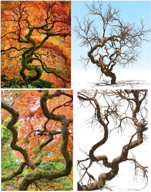
Figure 11 shows the irregular tree model compared with a real Japanese maple tree. The top row shows the global structures and the lower row compares the detailed features. The irregular tree model possess similar characteristics of real trees that we are interested, including the twisted primary branches, the crooked branch shapes, and the distribution of branches. These characteristics can hardly be created using previous methods.
[image:4.595.50.293.256.336.2] [image:4.595.301.554.432.551.2]Fig. 11. A comparison between a real tree (left column) and our irregular tree model (right column). Real tree photos from Flickr.com.
Fig. 12. More irregular tree models created using our algorithm.
V. CONCLUSION ANDFUTUREWORK
This paper presents an algorithm for 3D irregular tree modeling. The algorithm is built on the idea of path planning and guiding vectors. Through controlling parameters, to be specific, the rotation angle α of guiding vectors and the distance interval d to make rotations, we can create tree models with distinct irregular features: the scale of irreg-ularity is influenced byα, and the crookedness is controlled by d. Compared with the previous work, the algorithm can effectively create the desired irregular branch features while still keep the natural-looking tree characteristics. The algo-rithm also has its weakness: it is not good at reconstructing or duplicating a given tree structure. Fortunately it is rare that a movie or game requires a specific tree model from a real tree example, but often a tree bearing general irregular features. From this sense, our method can successfully meet the requirement.
It is worthwhile to mention that the work presented here is only an initial exploration of tree features. There have many possible directions for our future work. One direction is to develop more methods to control the existing parameters to
get more variations of tree models. For example, rotation angle alpha can vary with probabilities, e.g. 10% chance of π/2 and 90% chance of π/6. This can create richer con-trollable irregular features. Another possible direction is to create tree models with different distribution of irregularities. Branches closer to the outer contour of the tree crown show more small-scale irregularity, and those close to the root (which are often primary and thick branches) can have more large-scale crookedness. In addition, we also expect to apply the technique to the real applications of scene synthesis in movies and games. To animate the irregular trees can be a possible first step.
REFERENCES
[1] L. Xu and D. Mould, “Modeling dendritic shapes - using path planning,” inGRAPP (GM/R), 2007, pp. 29–36.
[2] ——, “Constructive path planning for natural phenomena modeling,” in3IA, 2008, pp. 59–69.
[3] ——, “Procedural tree modeling with guiding vectors,” Computer Graphics Forum, vol. 34, no. 7, 2015.
[4] ——, “Synthetic tree models from iterated discrete graphs,” in Pro-ceedings of Graphics Interface, 2012, pp. 149–156.
[5] ——, “A procedural method for irregular tree models,”Computers and Graphics, vol. 36, no. 8, pp. 1036–1047, Dec. 2012.
[6] H. Xu, N. Gossett, and B. Chen, “Knowledge and heuristic-based modeling of laser-scanned trees,”ACM Trans. Graph., vol. 26, 2007. [7] Y. Li, X. Fan, J. Mitra, D. Chamovitz, D. Cohen-Or, and B. Chen, “Analyzing growing plants from 4d point cloud data,” ACM Trans. Graph., vol. 32, no. 6, pp. 157:1–157:10, 2013.
[8] Y. Livny, F. Yan, M. Olson, B. Chen, H. Zhang, and J. El-Sana, “Au-tomatic reconstruction of tree skeletal structures from point clouds,”
ACM Trans. Graph., vol. 29, no. 6, pp. 151:1–151:8, 2010. [9] T. Capizzi,3D Modeling And Texture Mapping. Premier Press, 2002. [10] S. Ebert, F. Musgrave, D. Peachey, K. Perlin, and S. Worley,Texturing and Modeling, A Procedural Approach, 3rd ed. Elsevier Science, USA, 2005.
[11] P. Prusinkiewicz and J. Hanan, “Lindenmayer systems, fractals and plants,”Lecture Notes on Biomathematics, 1989.
[12] P. Prusinkiewicz, M. James, and R. Mˇech, “Synthetic topiary,” Com-puter Graphics, vol. 28, pp. 351–358, 1994.
[13] R. Mˇech and P. Prusinkiewicz, “Visual models of plants interacting with their environment,” inProceedings of the 23rd Annual Conference on Computer Graphics and Interactive Techniques, ser. SIGGRAPH ’96. ACM, 1996, pp. 397–410.
[14] T. Ijiri, S. Owada, and T. Igarashi, “The sketch l-system: Global control of tree modeling using free-form strokes,” inSmart Graphics, 2006, pp. 138–146.
[15] A. Runions, B. Lane, and P. Prusinkiewicz, “Modeling trees with a space colonization algorithm,” inEurographics Workshop on Natural Phenomena, 2007, pp. 63–70.
[16] W. Palubicki, K. Horel, S. Longay, A. Runions, B. Lane, R. Mˇech, and P. Prusinkiewicz, “Self-organizing tree models for image synthesis,”
ACM Trans. Graph., vol. 28, pp. 58:1–58:10, 2009.
[17] I. Millington and J. Funge,Artificial Intelligence for Games, Second Edition, 2nd ed. San Francisco, CA, USA: Morgan Kaufmann Publishers Inc., 2009.
[18] E. W. Dijkstra, “A note on two problems in connexion with graphs,”
Numerische Mathematik, vol. 1, pp. 269–271, 1959.
[19] P. Prusinkiewicz, “Modeling and visualization of biological structures,” inIn Proceeding of Graphics Interface, 1993, pp. 128–137. [20] A. Runions, “Modeling biological patterns using the space colonization
algorithm,” 2008.
[21] P. Ferraro and C. Godin, “A distance measure between plant architec-tures,”Annals of Forest Science, vol. 57, pp. 445–461, Jun. 2000. [22] O. Stava, S. Pirk, J. Kratt, B. Chen, R. Mch, O. Deussen, and B. Benes,
[image:5.595.48.292.403.486.2]