AD-760 757 REUTILIZATION OF THE MINUTEMAN GUIDANCE COMPUTER AS A NUMERICAL/PROCESS
CONTROLLER
Raymond V. Cicirelli, et al
Air Force Institute of Technology
Wright-Patterson Air Force Base, Ohio March 1973
DISTRIBUTED BY:
II
ped---Jvcsd by
NATIONAL TECHNICAL INFORMATION SERVICE
u S oof ce.','c'
UNITED STATES AIR FORCE
AIR UNIVERSITY
AIR FORCE INSTITUTE OF TECHNOLOGY
Wright-Patterson Air Force BaseOhio
_ - "-Unclassified
DOCUMENT CONTROL DATA - R & D
e.e.ruraty fle~slleraston of Mlie. &o•d of ah.rru.e and ende..n Annotafi•ajn njonf be entpirgd %hrn thr ý-rrl 7rpofrl ia elpisitled)
OqI-,oSO.A T7%G ACT I TY (COrtpeAIe Au-ht) -24. REPORT SCCUII TV C..ASSFVICAT'ON
Air Force Institute of Technology (AFIT-EN) Uncassified
Wright-Patterson AFB, Ohio 45433
R4EPORT TiTtt
* REUTILIZATION OF THE MIINUTEMIA GUIDAMICE COPUTER AS A NUMERICAL/PROCESS CONTROLLER
"DE" RIPTIVC NO."$S(TYP of ,epoet and lnCuassv* daer)
AFIT Thesis
S AI,.O~ SS. (S'Fs? arme. middle mn:lial. ja•: rmeeS)
Raymond V. Ei'irelli Jehn 14. HiIl
Lt USCG l/Lt USAF
4 REPGn'r DATE .76. TOTALMO PAGES 1b. NO. OF REFS
{
larch 1973 -111 RO 29ae CONTRACT OR GtHANT NO. 64L CRIG2HATORS REPORTrNUMgIERI$)
b. PRO,-,1 -o. GE/EE/73-5
C. i ~this 9b. OTP4CR ACPORT NOtS) (Any SPrQp / oth~r numbers 4%1 may be esam5ned
4.
0
o*TR1ST.T!No STATEMENT D1etails of illustrations in
Approved for public release; distribution unlimited, . •. ,unt may .betfce
t 'Afpt•'MW't Yfiblic release; IAW AF
--- ERR C.' • ". ' . Aitr Force institute of Techbnology'
JERRY C.. I!(, Captain, USAF Wright-Patterson ATB, Ohio
Director of Information A o
1 13 AVS1RAý-'
"As a result of the DU1B computers from the Minuteman I missiles heine made available to qualifying organizations, several studies have
been i-implemented to assess the usefulness and adaptability of the D17B
in other applications. This report is directed toward their use in
control applications.
The report outlines a few of the basic concepts oft numerical
control and process control toward the er.d of adopting these computers
to those purposes. The primary emphasis is on numerical ccrtrol with
merely a small account being given of process control. The primary
functional features of the computer are presented in detail for the D17B
and merely mentioned in passing for the D37C computer (Minuteman II)
with ih, expressed hope that the results of the work can be applied to
I
the D37C.An analog computer model of a machine positioning systen was developed in order to test the control that could be exerted on a
machine by the computer under program control. Various programs were
developed to control the machine model in X and Y coordinates. The
programs were able to control the machine model continuously over a
specified trajectory. Representative paths describing arcs of circles
and squares in arbitrarily selectable locations are presented as results. In addition the shaft-angle of a laboratory motor-trainer was controlled in discrete increments.
Unclassified
Sev'srity CV -sification
KYWRSLINK A LINK 0 L.INK C
_ _ _ _ _ _ _ _ _ _ _ _ _ _ _ _ _ _ _ _ _ _ _ _ _ _ _ _ _ _ _ _ _ _ _ _ _ R O L E W T II L * O L C W
iM
tinuteman Computer9
D17B Computer
D37C Computer
m
• tNumericai Control and Dl7B Computer Process Control and D17B Computer - Reutilization of Mlinutenman Computers
-•I.
"j
I
k g
C
D
if)JUN
6
LOBh
0
~~REUTILIZATIONOF THE
lT
EtLL
U+
9
IINUTEI.AN GUIDANCE COMPUTER AS A NUMERICAL/PROCESS CONTROLLER
- THESIS GE/EE/73-5
Raymond V. Cicirelli John M. Hill
Lt USCG 1/Lt USAF
.REUTILIATION OF THE MINUTEMAN GUIDANCE COMPUTER AS A NUMERICAL/PROCESS CONTROLLER
£ THESIS
Presented to the Faculty of the School of Engineering of the Air Force Institute of Technology
I
Air Universityin Partial Fulfillment of the Requirements for. the Degree of
Master of Science
110
by
Raymond V. Cicirelli, B.S.
Lt USCG
John M. Hill, B.S.E.E.
1/Lt USAF
Graduate Electrical Engineering P'arch 1973
Approved for public release; distribution unlimited.
GE/EE/73-5
Preface
We, the authors, must agree with the words of Professcr Gary B. Lamont. "A master's thesis is an educational experience." Innumerable bits and pieces of diverse information have been garnered in thie
,,ccomplisrment of this work. Hopefully some of these 011 provide t.e
setý-4 for future maturation in the field of engineering.
Professor Lamont, who supplied the original idea for this thesis project and advised us throghohut, must share our grateful appreciation with Lt. 1oseph Theriau.t - rendered invaluable assistance in learning
to use the 0 R ca-uter.
As alway, our w•ves and familiss are due a substantial amount of credit for the,-- support durirt ihq ; t'y-h,.3 period.
Raymond V. Cicirelli John M. Hill
"GE/EE/73-5
Contents
Page
Preface . . . . . ...
11
SList of Figures ... ... vi
List of Tables ... ... viii
Abstract
...
... . . .. . ixI. Introduction ... ... 1
Problem Analysis. ... 2
Numeri cal Control... .. .. .t. .. .. .. .... 3
Early Applications .. .. .. .. ... . .... ... . . 5
Early Prograiming Procedures ... ... 5
The Present . . ... ... 6
Proces, Control ... ... . 7
Levels of
Control
... .9Assumptions ...
11
Thesis Outline ... ... 11
II. D17B Computer ... ... 12
Physical Description ... . . . 12
Size and Composition ... 12
Power Requirements ... .... 15
Functional Description . . .. .. .. .. .. .. .. 16
Termnology of the D17B ... 16
Control Unit . ... ... 21
Arithmetic Unit ... 25
-•Memory
Memoryu'...2
... ... ... 26Inputs and Outputs... 30
Computer Word Format and Progranninng ... ... 30
Unflagged instruction ... ... 30
Flagged Instruction . . . ... 33
"Instruction Word Format ... ... ... 34
Full-Wo.d.Oerand... 3
SFull-Word
Operand 35 Split-Word Operand ... 35Phases of Operation. ... 37
Inpus
.. Inpu... ... ... Modes of Operation ... ... 39nptn ... 39
Cn rl inputs .. .. .. . . .. .. .. .. .. 3
Character Inputs .. .. .. .. .. .. .. . .. 44
Discrete Inputs . .. .. .. .. .. .. .. . .. 47
GE/EE/73-5
Contents
Page
Outputs
...
.. ... ... 51Discrete Outputs ... ... ... ... ... ... 51
Binary Outputs ... . . ... .53
Character Outputs ... ... 55
Voltage Outputs ... ... 55
Telemetry Outputs ... 57
Mode Control Monitor Signals ... ... 59
Incremental Output ... ... 59
Output Summary.. .o.... ... ... ... .... . .59
Specifications and Features Applicable to Control Operations... ... ... ... ... . . . 60
Inputs ... ... ... ... ... ... ... ... 60
Outputs
...
... 61Genera's ... ... ... 62
SIII. Model Formulation and the Impienentation of a Machine Positioning System ... 63
Servos and Drives ... 63
Field-Controlled Motors ... . . 63
Steady-State Response ... .... 67
Armature-Controlled Motors .... 68
Analog Computer Mlodel of a Two-Axis Positioning System .. ... .... 71
Parameter Selection. ... 71
Computerized Control ... ... ... ... ... 76
IV. Results of Control Implementation.... ... ... ... . 87
Method A, Point-to-Point Control . ... .87
Method B, Continuous Path Control ... 87
Method
C, Closed-Loop Control ...91
Error Analysis ... 91
V. D17B Software Analysis ... ... 95
Prograrming Development ... ... 95
Programming Techniques ... ... . 96
Programming in flumerical Control Applications . . .. 96
Post-Processor ... ... . .96
Possible
Configurations
...97
GE/EE/73-5
Contents
Page Bibliography . . . . .i... . . . ...
103
Appendix A: D37C Computer ... 106
Appendix B: D17B Computer Instruction Set ... . . . . 111
Appendix C: SQuare Generation Subroutine . . ... ... . 13
Appendix D: Circular Interpolation Subroutine ... . 119
Appendix E: Comparison of Minicomputers . . . . , . . 133 Vitae ... .. . . . .. ... 136
ii
I
CI
IC,
GE/EE/73-5
[image:11.630.64.548.108.707.2]C
List of FiguresFigure Page
1
Functional Block Diagram of Early NC System . . . . . 42 Control Levels in Process Control... . . . . 9
3 Comparison of the Complexity and Loading Present in The Four Levels of Process Control ... ... 10
4 Minuteman DU7B Minicomputer Sketch ... 14
5 Computer Power Flow ... . 17
6 Basic Functional Divisions of the Di7B ... 18
7 Accumulator Recirculation Register. . . . ... 20
8 Memory Registers and Loops ... ... 22
9
D-17 ConceptualMemory
Layout . . . ... 2710 Word Formats . ... ... ... ... ... 31
11 Instruction Word Format ... ... 32
12 Number Word Formats... ... ... .... 36
13 Access Timing . . . ... 38
14 Compute Mode Control (K) ... ... . 40
15 Noncompute Mode Veitch Diagram ... ... 41
16 D17B Computer Inputs ... ... 42
17 Load Codes . ... 46
18 D17B Computer Outputs ... . . . . 52
19 Binary Outputs ... ... . . 53
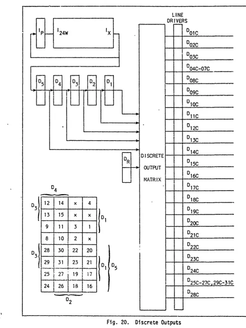
20 Discrete Outputs ... ... 54
21 Voltage Outputs ... ... 56
22 Simplified Diagram of Field-Controlled dc Motor .... 64
GE/EE/73-5
C,
List of FiguresFigu-e Page
24 Simplified View of Gear Arrangement for Worktable Slide 66
25 Closed-Loop System ... . . . . . 68
26 Armature-Controlled Motor and Load ... ... 70
27 Armature-Controlled Feedback System .... ... 71
"28 Root Locus ... ... ... ... ... ... 74
29 Initial Computer Diagram for Armature-Controlled Motor. 75 30 Selected Analog Computer Symbols ... ... 77
31 Analog Computer Simulation of Machine Positioning System ... ... ... 78
32 Coordinate Syscem of Simulated Positioning System . . . 79
33 Computer Positioning Control Incorpcrating Digital Feedback, Functional Diagram . ... ... 81
t34
ADC Hookup ... ... 8435 Square Figures Generated by Methods A and B .... ... 88
36 Circular Arcs Generated by Method B ... 90
37 Comparison of Arcs Generated by Mlethods B and C . . . . 92
38 Plot of Angular Position Changes Implemented by Method C ... ... 93
-•39 D17B asaController ... 97
39 Dl7as a oto~r...9
40 Supervisory Control ... ... 98
C-1 Square to be Generated ... ... 113
D-1 Geometric Representation of the Algorithm .... ... 119
D-2 Flow Chart for the Circular Interpolation Subroutine 130 D-3 Flow Chart for the Delay and Check Subroutine .... 131
D D-4 Flow Chart for End Point Determination ... 132
F
- GE/EE/73-5I.List
of TablesTable Page
I Gener;l Specifications of D17B Computer ... ... 13
II Recirculation Loops in the D17B Computer . . . 29
III Unflagged Instruction Fields ... ... 30
SIV Flagged !nstruction Fields ... 33
V Flag-store Location Code ... ... ... ... 34
VI Examples of Number Representation Used in the DI7B Computer ... ... ... ... ... ... ... ... 37
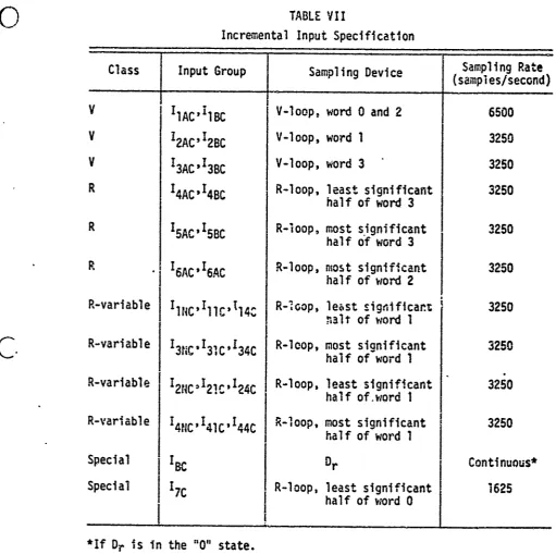
VII Incremental Input Specification ... ... 49
VIII Voltage Outputs as Determired by Phase Register ""_ Settings ... 57
IX Composition of Discrete Output Monitor Signals . . . . 58
X Useful Output Lines Available o... 59
XI Electrical Specifications of ADC-12QZ Analog-to-Digital Conrrerters ... 82
A-! General Specifications of D37C Computer ... 107
A-il Differences in Memory Capacities Between the D17B "and the D37C... ... ... ... ... ... 108
A-Ill Comparison of D37C and D17B Instruction Sets .... ... 109
B-! DI7B Computer Instruction Set ... ... D-I Special Characters for D17B Assembler . . . . . ... 122
S~GE/EE/73-5
•I
c
REUTILIZATION OF THE MINUTEMAN GUIDANCE COMPUTER AS A NUMERICAL/PROCESS CONTROLLERI. Introduction
The D17B and the D37C guidance and control computers are integral
- components of the Minuteman I and II missiles, respectively, which form
Sa part of the United States ICBM arsenal. The Minuteman III missiles, wihich us2 037D computers, complete the 1000 missile deployment of this
system. Due to the modernization of the Minuteman I system, the United Stdtes Air Force has declared approximately 1000 outdated inertial
guidance systems unserviceable (Ref 1:1). Each of these surplus Guidance
systems :ontains a D17B computer, unclassified parts of the stable plat-Sc. form, and power supplies. These systems are available to colleges and
other qualifying agencies for the cost cf shipping. In addition, as the Minuteman III missiles replace the Minuteman II missiles, the D37C computers will become available as surplus digital computers. It is expected that some 037C computers will be available as early as the fall of 1973.
The initial cost of these computers ranges from about $139,000
(D37C) to $250,000 (D17B). Since a large number of these computers have been or will 'e declared excess, a substantial savings could be realized
if these computers could be reused in other applications. This thesis will investigate the feasibility of using these computers in the areas of numerical control and process control. This chapter will cover a
brief background description of numerical control and process control,
GE/EE/73-
5
S
k Problem Analysis
-! -he problem that exists is to reuse surplus avionics computers to
I•
effect u savings of the money originally invested. Official Air Force{
policy is to discourage the procurement of computers except in certain designated application areas. Air Force Logistics Cormmand (AFLC) isinterested in the possibiiiy of using surplus computers which are being phased out along with their parent missile systems. As m,.ntioned pre-S- viously there are a number of D17B computers available for use in areas
that would benefit from the specialized features of a guidance and control
computer. A thesis (Ref 15) has been written on the general feasibility
A
of using riumerical control in Air Force depot-level shops and work centers. SIt also presents some of the special applications in the Air Force which"-I
- are particularly suited for numerical control. There are several
prob-"lem areas which should be considered if surplus minicomputers are to be
j-
reused.Among these problems is the relatively small main memory capacity of the 017B computer. Its memory is approximately the same as the
smallest available memories in current minicomputers. This imposes a limitation on total program lengths and computational capabilities. In addition, the memory access time is comparatively long since it has a serial access memory (disk) rather than a random access memory.
Compu-.ations take longer than desired due to this feature and to the serial
-- operation of the computer. Data are transferred into and out of the
computer serially, again imposing time constraints. A full grasp of the -'- peculiar characteristics of the instruction set available with this
- V• .- GE/EE/73-5
(
unique instruction set on this computer could prove to be a distinctadvantage in this application.
An operational D17B computer is available at AFIT and will be used for experimentation and study during this investigation. A D37C computer recently became available, but it is not operational at this
time. This requires that the study be based on the D17B computer and
later be extended to the D37C computer.
A final problem is the acquisition or generation of a suitable system to demonstrate the control applications of the computer. Initial
investigations determined that the Air Force has surplus numerical con-trol machines which ;an be obtained through DIPEC (Defense Industrial
Plant Equipment Certer); however, the lead time necessary to obtain such equipment, four to five months, was prohibitive in this case. In addition, charges for transportation, packing, handling, and crating would amount to several hundred dollars. Another aspect to be considered is the condition of a machine which has been stored for quite some time.
With these consi-erations in mind, standard laboratory and educa-tional devices such as analog computers or motor-control trainers would Sbe quite suitable for demonstration of the control characteristics of -
J
the computer. The use of the analog computer requires the generation ofa mathematical model of the system to be simulated. A two-axis linear
positioning system based on numerical control parameters will 'e simulated. •
f
The simulation will be developed fully in a subsequent chapter.Numerical Control
In the last 25 years many sophisticated new techniques have been -
(
{developed in the machine tool industry for the purpose of increasing theGE/EE/73-5
C-'
productivity and efficiency of machine shop processes. Numerical controlis one of the most outstanding of these new techniques. Numerical con-trol (NC) is the technique of concon-trolling a machine or process utilizing command instructions in symbolic form which are converted into automatic servomechanism control.
The first major efforts to implement a numerical control system were sponsored jointly by the U.S. Air Force and the Parsons Corporation of Traverse City, Michigan, in 1949. The project was carried out in the Servo Mechanisms Laboratory of the Massachusetts Institute of Technology. The project was not completed until 1953. A functional block diagram of
the system is shown in Fig. i. A feasibility demonstration in March
1952 sparked further work by the Air Force and private industry (Ref 25:1).
C.
This demonstration was performed using a three-axis Cincinnati Hydrotel vertical mill, a machine which shapes metal using rotary cutters."Computer u Position Desired
Faevooo
Sr t Slides ' Tool I •Psition"oInput Data
Possible , Actual Measured Position
--- ---. 1____________
Feedback
GE/EE/73-5
Early Applications. In the middle and late 1950's the aircraft
j
industry was the primary user of numerical control processes. The most practical way for the aircraft industry to irnplemert numerical control was to retrofit existing machines for numerical control. L the late 1950's, large numerical control machines were manufactured for applica-tions such as skin milling, the removal of small layers of surface metal. At the same time multiple-tool machines were developed. In 1956 the automatic tool changer was introduced. A drill with punched tape-controlled table positioning was announced in October 1961. Because of the low price of the system, its introduction represented a major economic breakthrough. By the end of 1962 all major machine tool manufacturers were engaged in numerical control (Ref 11:13).In the early stages of its development, numerical control required - close coordination of such things as input codes and input formats. By
1958 the need for standards was critical. The Electronic Industries Association (EIA) led the efforts toward standardization. They developed
a single standard (RS-244). Although this standard has been almost universally accepted in the recent past, the American Standard Code for Information Interchange (ASCII) will probably supplant it in the near future due to its more widespread acceptance in other fields, and its greater flexibility (Ref 11:13).
Early Programming Procedures. Manual progra.m.ing, being the most
straightforward way to obtain program tapes, was used extensively in the early days of numerical control. However, it suffers from computational complexities necessary to determine the appropriate conmmands required to direct the machine properly. Calculations such as surface intersections
GE/EE/73-5
were quite tedious to compute by hand. Early programirers needed a knowledge of analytical geometry, advanced algebra, trigonometry, and computer programming as well as machine tool operation, tooling, and machine practices (Ref 11:14).
Starting in 1956, several computer progranmning languages were developed which allowed the generation of complex command sequences through the input of simple statements and machining parameters. This "advance was a critical step in promoting the development of continuous-contouring to its fullest potential. Continuous-contouring requires
]
moving the cutting tool along a specified path rather than moving the tool from'point-to-point without regard to the path. Iost point-to-point (PTP) applications did not present such severe programing burdens, however (Ref 23:194).--
C
Numerical control programs were the first attempts at creating a conmmunication language between men and machines with the aid of a com-puter (Ref 11:15). The first language to bedeveloped (Ref 26:193) wasAPT (Automatically Programmed Tools). APT was soon followed by AUTOPROMT (AUTOmatic PROgramming of Machine Tools) and then by ADAPT (Air Force Developed APT or ADaptation of APT) (Ref 26:193). The inception of the smaller minicomputers led to the development of AUTOSPOT (AUTOmatic System for P(sitioning Tools), in 1g62, for point-to-point applications.
GE/EE/73-5
first method is computerized numerical control (CNC). This method _
10
involves the use of a controller (a device which converts coded commandsinto servo control signals) with limited information-storage capacity. Instead of feeding a punched tape directly into a numerical control machine, the program. is stored in a centralized computer and fed to the controller in blocks. The controller then directs operation of the .machine until it reaches the end of that particular block of instructions
a1at which time the computer transfers in a new block of the program to the
controller. The single computer can control several machines in this manner, obviously resulting in a more efficient utilization of the com-puter and eliminating the need for a tape reader for each machine.
The second method is DNC (Direct Numerical Control). In this method there is no tape reader or interirediate controller. Feedback and control lines go directly between the computer and the machine tool
rather than to a controller. The advantages of this method are (1) costs are reduced by the absence of tape readers and controllers and by simpli-fied electronic equipment, (2) the computer can be located remotely from the tool, (3) programs can more easily be adjusted in real-time in
response to adaptive control, and (4) the computer can control more than one machine simultaneously or shift from one machine to another as the situation w:arrants.
Process Control
The digital computers used in process control are generally
general-purpose computers similar to those used for business or
scien-tific data processing. In addition they are provided with analog
I/O
C.
systems and relatively sophisticated priority interrupts.f
;GE/EE/73-5One of the first large-scale process control systems using a computer was at a Texaco refinery in 1954. Since that time hardware and software have changed considerably. Many larger systems now employ problem-oriented languages and on-line compilers and assemblers compared to the original efforts using machine language programming (Ref 27:84). Boiler-turbine-generators rated above 250 megawatts almost invariably use computer control for startup and shutdown (Ref 21:84).
Although the early use of computers in process control was in data logging, data analysis, and empirical model-building, the more recent attempts have been in closing the control loops through the computer itself (Ref 27:84). Even more recently the emphasis has been placed on direct digital control (DDC) (Ref 24:85). In this application the com.-puter replaces a majority of the analog elements of the system and applies activating signals directly to the final control elements of a process.
Although analog process controllers can implement cascade, feed forward, and feedback control algorithms, they are generally not adaptive. In addition, it is difficult to implement snme forms of nonlinear control and to integrate the contrnlling function with sequence control or
Soptimization straLegy. The,.e functions can readily be implemented by digital computers.
In addition to the technical advantages of using computers, there are associated intangible benefits which sometimes accrue, such as more =
11accurate
process knowledge, greater safety, or better control of productquality. Better control of the product, coupled with a more accurate knowledge of the process, can result in more quality in the finished Sproduct, resulting in fewer complaints and fewer rejects. Conversely,
GE/EE/73-5
with a low reject rate, resulting in lower production costs.
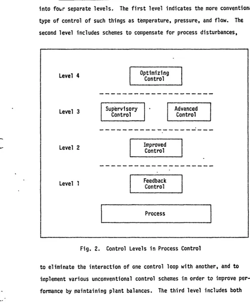
~ Levels of Control. Figure 2 shows a division of process control into four separate levels. The first level indicates the more conventional
jtype
of control of such things as temperature, pressure, and flow. The"second level includes schemes to compensate for process disturbances,
Level 4
I
OptimizingI
Co nr Control
---- Level-Improved
I
SLevel 3-oto
• Control Coto
Level I Feedback
Control
I
ProcessFig. 2. Control Levels in Process Control
to eliminate the interaction of one control loop with another, and to implement various unconventional control schemes in order to improve per-formance by maintaining plant balances. The third level includes both
[image:22.614.70.568.113.715.2]GE/EE/73-5
supervisory and advanced control. The supervisory function automatically changes conditions as warranted by examination of plant performance. Also
included in this category are sequence control for batch operation as well as automatic startuD and shutdown of continuous subsystems. The
advanced control function includes adaptive control to enable automatic compensation for such things as aging catalysts in chemical reactions. The fourth level optimizes operating conditions in the plant using such factors as inventory prediction, economic scheduling, and dynamic pro-gramming. It should be noted that higher levels could be added to include
the divisional and corporate level management informnation systems.
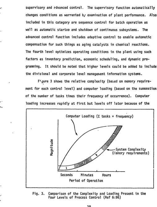
F4gure 3 shows the relative complexity (based on memory require-ment for each control level) and computer loading (based on the sunflmation of the number of tasks times their frequency of occurrence). Computer
loading increases rapidly at first but levels off later because of the
Computer Loading (Z tasks x frequency)
43
wSystem Complexity
(remory requirements)
Seconds Minutes Hours Period of Operation
Fig. 3. Comparison of the Complexity and Loading Present in the
[image:23.614.65.574.67.737.2]GE/EE/73-5
decrease in frequency at higher levels. On the other hand, complexity increases rapidly with the control levels because of increased memory
requirements.
Assumptions
This thesis is written with the assumption that the reader has a basic familiarity with computers and control engineering. It will be
* • assumed that the D17B computer at AFIT will be available, in suitable operating condition, for experimentation during the period of the inves-tigation. It will be further assumed that the control functions can be applied by the computer in a dedicated status, rather than being inter-rupted at random, to perfor,,- other tasks. Since the D37C has all of the features of the D17B plus others not available to the Dl7B, the final assumption will be that the operations of the D17B computer can be per-formed by the D37C. The additional capabilities of the D37C are discussed in Appendix A.
Thesis Outline
Chapter II of this report presents a physical description of the D17B computer with 3 detailed treatment of the inputs and outputs. Chapter
III discusses the formulation of a model of a machine positioning system and implementation of the control system. Chapter IV rresents the
*• experimental results obtained, and Chapter V presents conclusions and i
i
recommendations for future investigations.U
GE/EE/73-5
*I
c
II. D17B Computer
To give the reaeer an understanding of the capabilities of the Dl7B computer this portion of the report will start with the physical description followed by the functional description which will include discussions of the control unit, the arithmetic unit, and the menory.
* Next, computer word format and programming will be described. Included
in this section will be the instruction word fomat, full and split word
formats, and the phases of operation. -The next two subsections will describe the input and output functions including special features appli-cable to numerical control. The final subsection will describe control
- ~ features usable for numerical control as well as certain specifications
II=
of the D17B which are applicable to numerical control.The general specifications for the D1IB computer are listed in Table I.
Physical Description
Size and Composition. The D17B is a guidance and control avionics computer built by Autonetics, a division of North American Rockwell, as part of the Inertial Guidance System (model HLS-lOQ) of the LGM 30/Minuteman
iCBM Missile. The Inertial Guidance System also includes the associated stable platform and power supplies. The D17B computer occupies one half of a 12-sided, right-polygonal shell, as sketched in Fig. 4. This shell is 20 inches high, has a maximum radius of 29 inches, and is five inches in depth.
General Specifications of D17B Computer
Manufacturer Autonetics
Year 1962
Type Serial, synchronous
Number system Binary, fixed point, sign plus ?'s complement Logic levels False (0 volts), True (-10 volts), negative
logic
Data word length 24 bits (full word)
11 bits (split word) Instruction word length 24 bits
Number of instructions 39 Execution times
Add 78.125 usec
Multiply 1015.625 lisec
Divide Software
Cikck frequency 345.6 kHz
Addressing Direct addressing
Two-address (unflagged) Three-address (flagged)
Memory Ferrous-oxide coated disk
""lon-destructive readout 2727 (24 bit) word capacity 78.125 psec cycle time
]Input/C'jtput
48 digital lines 'input)26 specialized incremental inputs 28 digital lines (output)
S12 analog lines (output)
13
pulse lines (output)25,600 words/sec maximum I/O transfer rate Physical characteristics
Dimensions 20 in. high, 29 in. diameter, 5 in. deep
Power 28 VDC at 25 A
Circuits DRL and DTL
Weight 62 pounds
(Adapted from Refs 4:2 and 1:4)
GE/EEf/73-5
IN
-
I-be$ avial
GE/EE/73-5
The power supply for the complete 1NS-lOQ guidance system is contained in the other half of the shell and the stable platform is in the cavity formed m by the computer and power supjlies.
The D17B weighs approximately 62 pounds, contains 1521 transistors,
6282 diodes, 1116 capacitors, and 504 resistors. These components are mounted on double copper-clad, engraved, gold-plated, glass fiber laminate circuit boards. There are 75 of these circuit boards and each one has been coated with a flexible polyurethane compound for moisture and vibra-tion protecvibra-tion (Ref 18:16).
Since an airborne, computer-controlled missile only gets one chance to execute its mission, the design specifications of the D17B required very high reliability. This was achieved by using DRL (diode-resistor) logic extensively and only using DTL (diode-transistor) logic where gain
(
was required in this fully solid-state computer. In the early 1960's when the Dl7B was designed, transistors were not as reliable as they are now, thus the designers used transistors only when necessary. The rotating disk memory, with non-destructive readout (NDRO), also enhanced the reliabilit, of the computer. in actual, real-time situations involvingMinuteman -missiles, the mean time between failures (MTBF) was over 5.5 years.
Power Recuirements. If the power supply included in the NS-IOQ guidance system is used for the D17B, a 28 VDC regulated power supply capable of supplying 25 A is the only external power supply needed for operation of the computer. Other required voltages are obtained by converting 20 VDC into secondary power using solid state circuitry in
the power supply section of the Inertial Guidance System. The current drawn from the 28 VDC power supply will vary from 0 to 25 A with a
GE/EE/73-5
steady-state value af 19 A (Ref 4:25). The computer may be operated
without the associated power supply: however, it would then be necessary
to supply 14 separate DC voltages as well as 1200 Hz and 400 Hz
alter-nating currernt supplies. The secondary power reQuirem.ents are shown in
Fig. 5. Power consumption for the computer is approximately 350 watts
(Refs 4:25 and 1:3).
Functional Description
The D07B computer is a general purpose, serial, binary minicomputer
with the following general capabilities.
1. Sampling and processing of input data in the form of control
signals, binary data, discrete signals, or incremental signals.
2. Logical decision-making, performance of arithmetic operations,
- c
and a logical AND operation using an instruction set of 39machine language instructions.
3. Transmission of output data in the form of analog, binary,
single character, or discrete signals under program control.
There are five basic functional divisions to the D17B: the Control
Unit, Arithmetic Unit, Memory, Input, and Output. This functional division
is shown in Fig. 6, with the Central Processing Unit (CPU) encompassing
the Control Unit and Arithmetic Unit.
Terminology of the
D17B.
The terminology of the D178 consists ofa number of basic terms which are common to the five functional divisions
of the computer. To help clarify the descriptions of these divisions, the
basic ternms will be explained first.
Bit is the name for the amount of information that is contained in
GE/EE/73-5
w C
-. j 4
CL.
W-
I__
a -
:-fJ I~
cz 4 C3
~.
1
C
-H-CD n w I
+S -j C)I
c~Ec
S. * an A, na
jc> 0
j0-0A UJ CJC.
3 ti a.
C>
V) '-4
co;:3: EL
GE! EE/73-.5
CD LU _j
I--
U < 5
-I A I
a
*i V)wc.a 9
5
2i
CDJ M:s
ul ) c u
u- CD
4Z-LU9 LU> -cc~
C) cx =- CCc
'- 01
tU.
Lgo
ui 0- c
wfUI-GE/EE/73-5
bits and 3 timing bits, may be used as data (input or output), an
instruc-tion, or a control signal in the DI7B.
A bit may be stored in a basic storage unit, a cell; the flip-flop
is the most widely used type of cell in modern technology. A collection
of cells joined together is called a egi.ster, Thus a 24-bit word can be
stored in a 24-cell register (Ref 7 :11). Most registers are constructed
as collections of flip-flops to allow simultaneous or parallel access to
all bits in the register. Since the D17B is a serial computer,
simul-taneous access to all the bits of a register is not necessary, thus
flip-flops are not needed for the en;tire register. Registers or
recirculating loops are composed of flip-flops and storage cells (on the
magnetic disk memory) as illustrated in Fig. 7. This example of a
recircu-lating loop is the A-loop used in the Arithmetic Unit. Ac, Ap, A3w,
Sand Ax are flip-flops and the rest of the loop is on the memory disk. Information is read through the read flip-flop Ax, then fed to the input
of the write amplifier and is rewritten on the next consecutive portion
of the disk. This forms a closed loop with the information recirculating
through this loop. The information first written on the disk remains on
the disk as that portion of the disk moves out of the loop, then it is
erased by the fixed erase heads (Ref 18:30).
The term word-time is derived from the length of time required to
Scirculate the complete 27-bit word in a one-word loop, and is 78-1/8 psec.
A word-time can be divided into 27 bit-times since one bit is one
twenty-seventh of a word (Ref 1:7).
The 24 information bits in a computer word may be subdivided into
fields of various lengths. These fields may be decoded to indicate
(.
specific information such as operation codes, operand addresses, andGE/EE/73--6
110u
II
- - GE/EE/73-5
next instruction addresses. The various fields will be explained in detail in the Computer Word Format and Progranmning portion of this report.
Control Unit. The Control Unit processes and iiterprets all
-
•
machine functions and controls two incremental inputs. Generally, in
j
computers with sequential operations, the Control Unit goes through three cycles: the fetch cycle, the execute cycle, and the defer cycle. The defer cycle is used for indirect addressing which does not exist in the DI7B. Computers with delay type memories like the D17B divide the fetch and e)ecute cycles into phases. in the D073 the fetch cycle consists of the instruction search phase and the instruction read phase. The Control Unit must.search for the instruction location as the disk is rotatingand then transfer the instruction from memory to the Instruction Register or he I-loop. Then the execute cyclewhich is sub-divided into the
IIE
ope'and search phase, operand read phase, and the execute phase, is entered.Dui ing the execute cycle the Control Unit searches for the operand location
i
as the disk is rotating and then transfers the operand to the NumberRegis-tei or N-loop within the Control Unit. Then the instruction is executed. The main component of the Control Unit is the Instruction Register I ( ee Fig. 8). The Instruction Register or I-loop contains a 27-bit word which is composed of one delay flip-flop 1p, one write flip-flop 124w, one -ead flip-flop Ix, and 24 other bits written on the magnetic disk memo -y. New information may be entered into the I-loop when the control
flip flop Ic is "one" set; otherwise, the information circulates from the magnetic disk through the flip-flops and is rewritten on the disk in a cont nuous loop (Ref 1:9).
Instructions are transferred from memory to the I-loop where the
K:-
instruction is held for part of the interpretation process. The instructionGE/EE/73-5
I-- ui L
ol fl
aLn 0a
1.81
0LOI~
'0.
a--t a w
Li)
tn c o . .0.
IlM Com/
M qw
cm c cmJ
C& 'us
cc0
LU I-l
C~J Lcc
GE/EE/73-5
word is separated into fields such as the operation code, bits 21-24; and the operand channel information, bits 8-12. These bits of informa-tion are transferred to buffer registers for temporary storage and then to storage registers to be held until they are executed. Once the infor-mation is transferred to the buffer registers, the Instruction Register is free to receive the next instruction (Ref 2 :16).
The operation code is transferred serially from the I-loop to the Operation Code Buffer Register (flip-flops Ip, Ob3-Obj). This code is
then parallel loaded into the Operation Cede Storage Register (flip-flops
I
03-01) where the operation code is held for' and during execution. In a Ssimilar manner the operand channel information is serially loaded into
the Operand Channel Buffer Register (flip-flops Cbs-Cb1) and then parallel
loaded into the
Caera~id
S'tnrav Pnist;ir - , a -flopý CC. PoI
register refer-nce instructions which do not require operands, the channel storage flip-flops may be used as additional hardware to execute theinstruction. Character output operation 's an example of this application. Four bits of the accumulator are shifted into the Channel Storage Register, then output on the character output lines.
Flag storing is a special operation which allows the execution of a store operation with the initiation of other operations (such as add or multiply) during one word-time without requiring an additional instruction. Using the flag stcre capability saves one word of We•mory and one word-time because a store instruction does not have to be used, The previous contents of the Accumulator are stored in a channel specified by the cide in T19, T18, and T17 which indicate bits 19, 18, and 17, res-pectively, in the instruction word as shown in Fig. 11, page 32. This
~2C
GE/EE/73-5
code is read into the Flag Code Storage Register at the first bit-time of execution. Flag storing will be explained in more detail under Computer Word and Progranming.
When an operand is read from memory it is loaded into the Number
Register or N-loop (see Fig. 8). The N-loop is in the Control Unit and consists of three flip-flops, tp, N24w, Nx, and 24 bits of memory. The flip-flop NP is used for delay, N24 for writing on the memory disk, and
-* Nx for reading from the N-loop. A fourth flip-flop Nc controls the entry
of new information into the N-loop (Ref 1 :10).
The Phase Register consists of flip-flops P1, P2, and P3. It is
used to select one of four external pQsitions for each of the three analog voltage outputs. The Phase Register can also modify the operand channel address of the multiply-modified and the split-word multiply-modified
; - instru.-lops. Further, the Phase Register has an input function as a
seiector sitch for choosing one of two pairs of inputs to one of the incremental pulse-type input loops, V or R.
Other registers in the Control Unit are tnree voltage output
*
•registers of 8 bits each which are used as inputs to D/A converters, and S[ a Discrete Output Register (Ds-D1) which, together with a Discrete
Output Matrix, controls the 28 Discrete Outputs. Also, there is a Binary Output Control Register which consists of three flip-flops, G3, G2, and G1.
A bit counter that is controlled by the sector track of memory Is
I
used for timing control in the D17B computer. The bit counter is a set- of 6 flip-flops that are used to distinguish bit-times for the serial
operations of the computer. These flip-flops are designated B1, B2, B3,
B4, 85, and B6. Three additional fllp-fiops, Tp, Tx, and To, are used
=7. - - '- - °- . ...- -" " --... .. - " '-• - "; -. . ',-- - " " "- • ••-' •,
GE/EE/73-5
B is used to distinguis between even and odd bit-times and B2 is "one"
- set at alternating two-word-time periods. B3 is 'one" set only during
the right and left split-word bit-times. B4 and Bs are counting flip-flops that are used in conjunction with the other flip-flip-flops of the bit counter. B6 is "zero" set during the first half of the word-time and "one" set during the second half (Ref 19:23-24).
Sunmmarizing, the major components of the Control Unit are: the Instruction Register; the Number Register; the Operand, Channel, and
* Flag Code Buffer and Storage Registers; the Phase Register; the Output Control Registers; and the Bit Counter.
Arithmetic Unit. The purpose of the Arithmetic Unit is to perform the calculations as directed by the Control Unit. There are two one-word registers in the Arithmetic Unit: the Accumulator and the Lower Accumulator.
The Accumulator, or A-register, accumulates the results of all the arithmetic functions and the one logical function. It also serves as an output register for voltage outputs, binary outputs, character outputs, and telemetry (Ref 18:17). The A-register as shown in Fig. 8 is composed of two delay flip-flops Ap and A24, a write flop A23w, a read flip-flop Ax, and 23 bits on the magnetic disk memory. When the control flip-flop Ac is "one" set, new information may be entered into the A-loop, but when Ac is "zero" set the loop recirculates and new information cannot be rea. in (Ref 18:30).
The Lower Accumulator or L-loop is used in conjunction with the Accumulator for certain arithmetic and logic operations. It is used in all the multiplication operations, Multiply, Split-Word Multiply, Multiply
Modified, and Split-Word Multiply Modified. The m, tiplier which was in
(
the Accumulator is shifted into the L-loop in reverse order (the LSB isGE/EE/73-5
in the MSB position). The Logical AND to Accumulator operation logically AND's the contents of the Lower Accumulator to the Accumulator. Another
function of the L-loop is tc receive character inputs during loading
operations and transfer these inputs to the Accumulator or the Instruction Register. The L-loop also serves as a rapid-access loop which allows data to be stored into or accessed frum the L-loop in one word-time. The L-register, as shown in Fig. 8, consists of 23 bits in memory, two delay flip-flops Lx and Lp, one write flip-flop L2 4, and a read flip-flop Lo (Ref 18:31).
Memory. Memory in the D17B is a rotating magnetic disk using non-return-to-zero recording. The disk is driven at 6000 rpm 1-y a
400 Hz, 3-phase hysteresis-synchronous motor. Information is transferred to the magnetic disk by 68 stationary read and write heads and remains
C.on
the disk until new data is recorded. This information is in non-volatile storage and remains scored even when power is removed from the computer. This is not true of the rapid-access loops which are partially on the disk. These loops are considered as volatile storage because the flip-flops that are a part of the loops or registers will be activatedfin a random state when power is restored.
The memory disk is divided into 32 concentric tracks (channels) and each channel is divided into 128 radial sectors as shown conceptually
in Fig. 9. The 32 channels are numbered in even-octal progression from
00 to 72 plus the I-loop and the sector track which are not numbered.
* iOnly even numbers are used because the least significant bit of the octal number used fo." channel addressing is reserved for the sector address. The sector numbers are permanently recorded on a special sector track S,
GE/EE/73-5
01 013 014 Is5 310
~ ~>)
I--+
ell
ftA
ICQ
~Z 0
LCJ UJCU UJ !JJ U
cez
v__CL___
0CC
27
GL1::" '3-5
timing purposes In the computer. The sectors are numbered octaily from 000 to 177. Each address, 03738 for example, designates the channel and
sector as shown below:
a
I
0 3; 7 3 OCTAL
000 0i1p M1 Oil0 BINARY
CHANNEL SECTOR
000 010 001 111 Oil pseudo binary
0 2 1 7 3 pseudo octal
Thus when 03738 is decoded as channel 028 sector 1738 it can be located in memory or in a conceptual layout of memory such as Fig. 9.
Program security or memory profection can be maintained b. disabling the write heads to channels 00-46, the "cold-stcrage" channels, resulting in a read only memory. The various rapid-access loops and channel 50
.
(the "iiot-storage" channel) could szill be written on.
In addition to channels 00-50, there ire ten recirculating loops which are used as input, arithmetic, and rapid storage operations as show,1 in Table II.
There are 2727 prograrnable words in memory (21 channels of 128 .
I
words plus 8 loops with 39 more words). The memory cycle time is 78-1/8GE/EE/73-5
II
Ill
CTABLE
II
Recirculation Loops in the D17B Computer
Channel Loop Words in Channel Function
52 F 4
54 H 16
Rapid access loops
56 E 8
60 U 1
,2 A 1
164
L 1 One-word arithmetic andI rapid-access loops
66
N
__I
Instruction loop-•- •.nonaddressab! e
70 V 4 Input buffer loops for
72 R 4 incremental inputs
-74
Interrediate read heads*
*HmL and Em are not separate loops--they are part of the H and E loops, respectively.
I
29
7 GE/EE/73-5
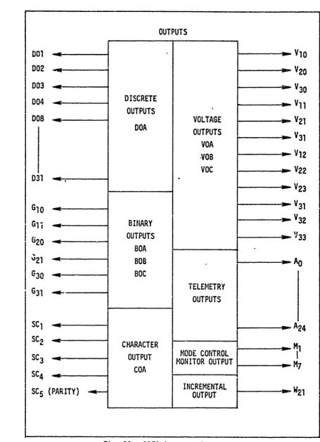
Inputs and Outputs. The Inputs and Outputs of the D17B Computer will be covered separately under Inputs and Outputs because of its
impor-tance to numerical control applications.
Comouter Word Format and Prc-;r,."..inQ
Word size in this computer is 27 bits, but 3 bits are used for timing, resulting in a 24-bit, programmable word. TI .s 24-bit word is presented in three basic formats: whole number, split number, and instruction. These formats are shown in Fig. 10. The two forms of the instruction word fo".iat--uniflagged and flagged instructions--are shown in Fig. 11.
"Unflagged Instruction. The u~vflagged instruction will be discussed fIrst since it is used as a basis for the flagged instruction. The unflagged
instruction is identified by the flag Lit T20 set to zero as illustrated m
C
in Fig. 11. The unflagged instruction has five fields as shown in Table III.TABLE III
Unflagged Instruction Fields
Bit Position Field
T24 -T2 1 Operation Code
T20 Flag (always zero)
T19 -T1 3 Sector of next instruction T12 -T1 Operand address:
VT 12 -Tg Operand channel
I
~GE/EE/73-5
Fx a X
I-C.>0
C
C>
F-f
- 0
F-- o
F-c F 1- :
IJJ <cc
c.4 am
' 0 U.
tai
CU.
1-4
C-4V
I- - c
CC-,
CL c
-3
Z4 3 0
:K 0
GE/EE/73-5
>CC
I--c
I---LU) Lnj
t.-
Iý-'44
0 0
-U
-X f
C-; = V)-6
F- C3 0 .
co p c ) 0
Cý I-- 1- p~
'4 4 'C
-C1
L. -i crc -F- 0
.-I--.,~~t.I- '
I2=
NL 0 Nj
~Cvi LU N L
C3F- F- a.
4. .
-S....
.: -- - -2. • . . -• -• • ... - .- - • '-.'°-• . '-• - . -•<- • • :f : ••<
GE/EE/73-5
This format is commonly called a two-address instruction although it could
_
111be
called a 1-1/2 address instruction. The two addresses given in theinstruction are the next instruction address and the operand address. Only half the address for the next instruction Is explicitly shown; the channel is assumed to be the same channel that contains the present instruction. The unflagged instruction format may be used with all 39 instructions listed in Table B-I, Appendix B.
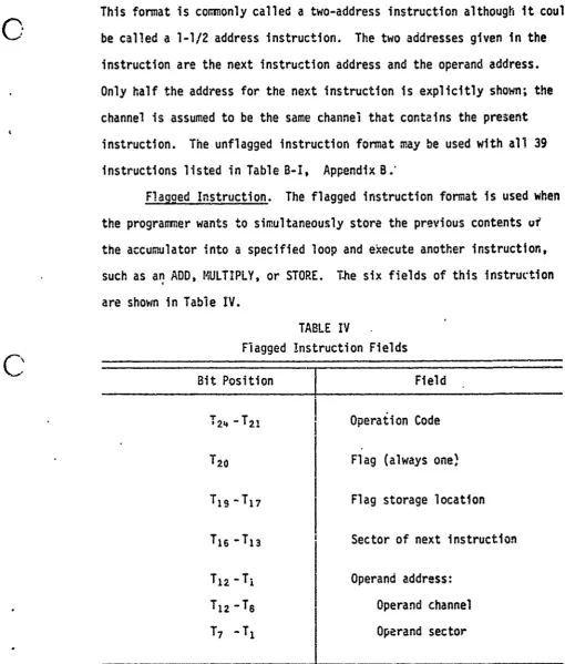
Flagged Instruction. The flagged instruction format is used when
j
the programner wants to simultaneously store the previous contents ufthe accumulator into a specified loop and execute another instruction, such as an ADD, MULTIPLY, or STORE. The six fields of this instruction are shown in Table IV.
TABLE IV
Flagged instruction Fields
-
-Bit Position Field
T24 -T2 1 Operation Code
_ T20 Flag (always one)
T19 -T1 7 Flag storage location TI6 -T13 Sector of next instruction
T12 -Tj Operand address:
* T1 2 -T6 Operand channel
T7 -T, Operand sector
[image:46.614.61.572.80.680.2]GE/EE/73-5
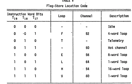
The flag-store location refers to a 3-bit code as shown in Table V. The address of the next instruction Sp is shortened to four bits since the
J
flag-store location code uses three bits. This limits Sp to the 16 sectors following the operand address specified in the flagged instruction. The flagged instruction is considered a three-address instruction.TABLE V
Flag-Store Location Code
Instruction Word BitsLoop Channel Description
--
I
T19 T1 8 T1 7 L
0 0 0 -- Idle
0 .0 1 F 52 4-word loop
0 1 0 T - Telemetry
0 1 1 - 50 Hot channel
1 0 0 E 56 8-word loop
S1
0 1 L 64 l-word loop1 1 0 H 54 16-word loop
S1
1 1 U 60-word loopInstruction Word Format. In both the unflagged and the flagged instruction word format the operand address (channel and sector) is 12
bits, which allows direct addressing of 4096 words. Since the D17B only
[image:47.614.130.573.220.503.2]GE/EE/73-5
A c
The operation code field in both cases is 4 bits long, which limits the D17B to 16 unique 4-bit op codes. The 13 instructions which address memory, use these 4-bit op codes and 12-bit operand addresses. Two of the remaining 4-bit op codes are used for register referenceinstructions such as control, logic, I/O, and shifts. The channel portion (T1 2-T8) of the operand address is used as an extension of the operation
code in instructions which do not access memory. Op code 14 is not used, which would allow another memory reference instruction. Also, there are numerous, unused 5-bit op code extensions which could expand the instruc-tion repertoire (Ref 4 :14).
Full Word Operand. All 24 bits may be used to store one operand. Bit 2A is the sign bit and T23-T, represent a 23-bit fraction in two's complement form (see Fig. 12). p, To, and Tx are timing bits used by the computer and they are not prograrimable. Examples of the number repre-sentation in the D7Baregiven in Table VI.
Split-Word Operand. Two numbers may be stored in one 24-bit word.
The left half-word is formed by bits T24-T14 and the right half-word is formed by bits T11-T1. As shown in Fig. 12, bits T12 and T13 are not used, and bits T24 and T1 1 represent the sign hits. Examples of
split-word operands are given in Table VI.
The D17B has the capability of simultaneous execution of two identical add, subtract, or multiply instructions on the left and right
I
half-words. This increases the speed available for a solution to a problem but with a loss in accuracy because only 11 bits are processed
SI for each half-word rather than 24.
SI
.
1
.3GE/EE/73-5
[0l
-4 -4
N
-q-LU CL.
Ca 4
in In
CDJ
m 40
I.- I
I- 4
en
No CD) to I
usa.
La ý
Es Es:PC
GE/EE/73-5
TABLE VI
C•
Examples of Number Representation Used in the D17B Computer (Octal numbers are presented for convenience;the computer uses binary numbers) Type of Format
Type of Number Split-Word Format
Full -Word Format
Left Half-Word
.
Right Half-WordS~I
Maximum positive number 3777 7777 3776 1777
Maximum negative number 4000 0000 4000 2000
M
Minimum positive number 0000 0000 0000 0000
"I Minimum negative number 7777 7777 7776 3777
I
Phases of Operation. This computer has five phases of operation which are coninon to delay-type memories. These phases are instruction search (IS), instruction read (IR), operand search (OS), operand read (OR), and execute (EX) as noted earlier. The upper part of Fig. 13 illustrates how these phases would be performed in normal sequential operation. Thelower part of the figure illustrates how the 017B computer can perform - several of these phases simultaneously. This figure assumes ninin,&e delay
coding of instructions which require one word-time for executior;. The advantage of a minimal dealy code program is that, once the program is initiated, the effective completion time of any instruction is equal to the basic execution time of that particular instruction. Minimal delay coding means placing the next Instruction in the memory location which will be read next, following the execution of the present instruction.
[image:50.614.58.585.109.733.2]GE/EE/73-5
CD Lai
'-3 m.
:K a
cv cv
I - - - - - -- - - - - - - - - - - - - - - -
-Cli
0 - - - - - - - - -- - - - - -
-9-. C
tnn
--- -- --- --- --- -- -- --- -- --
---n
m
0iJ C%4 cn cv)
fnI
-GE/EE/73-5
M!4odes of Operation. The modes of operation can be considered as the types of operation that the computer may perform. The D17B has two basic modes, compute and non-compute. Compute mode involves the execution of instructions and the non-compute mode involves operations such as
synchronization and reading instructions (Ref 1:59). These modes are divided into submodes as indicated in the Veitch Diagrams (Figs. 14 and 15). Reference I presents the state description and the associ~ted
register transfer equations for the modes and submodes if a more detailed presentation is desired.
Inputs
Because the Inputs and Outputs of the D17B were designed for use in the Minuteman I ICBM, many of the Inputs and Outputs are special pur-pose signals. Another factor to consider is that the D17B provides
access to approximately 550 lines through connectors J1-J1 1. These lines include the Input/Output signals, control signals, power monitoring signals, and some spare lines.
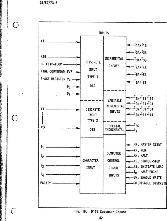
The input lines as illustrated in Fig. 16 can be divided into four classes of inputs: Discrete inputs, Character inputs, Incremental inputs, and Control inputs. The Discrete and Character inputs are used for data inputs, whereas the Control inputs are usually signals from a control console. The Incremental inputs are independent of program control and are used in highly specialized applications.
Control Inputs. The Control inputs consist of eight signals:
F
Master Reset (MR), Run (KR), Halt (N.): Single-step (KS), Initiate Load (FS), Halt Prime (IM), Enable Write (EW), and Disable Discretes (DD).GE/EE/73-5
C)
UI-u1 CCC l C
cc w
-IJcc
LA L" LL 4
0. .
OW- LL.0
Co I
0i%
w0
0.0
-~+ a
tw. 2L W " U 4
Z D L UJ
I- U ~ LUI- (A L&
'n LU CCXL
0..
*L U m C
03 w + qcc
A
_________I
cc_ __ _ __ _FL<