One remedy for this situation is to install handpumps on wells,
wherever possible. However, most handpumps used in developing
countries today are imported from the developed world where the pump
is designed to be used by one family.
These pumps cannot stand the severe use required in developing
countries, working continuously every day for 6-7 hours. Most avail¬
able handpumps are expensive, complicated, a high percentage are
inoperative. This report reviews all available testing and experience
with handpumps. This information is summarized for each type of pump
and criteria for evaluating the different pumps are presented.
The report commends one very simple handpump, the Blair Pump, in
which polyvinyl chloride pipes are used as the pump cylinder and piston.
In addition, seven other pumps, for both deep and shallow wells, are
deemed most appropriate for developing countries. Recommendations for
I. INTRODUCTION --- 1
Need for Handpumps --- 1
Handpumps --- 3
Nomenclature --- 4
Principle of Handpump Operation --- 4
Rate of Discharge --- 7
Energy Requirement --- 8
Problems with Handpumps--- 10
Information on Handpumps and Their Problems --- 11
The Objectives of the Report --- 12
Sources of Reference --- 13
List of Handpumps --- 13
Background onHandpump Laboratory Testing and Experience --- 15
II. PUMPS WITH DESCRIPTION, LABORATORY TESTING AND FIELD EXPERIENCE--- 19
III. PUMPS WITH DESCRIPTION AND FIELD EXPERIENCE --- 130
IV. PUMPS WITH DESCRIPTION AND FIELD EXPERIENCE --- 153
V. PUMPS WITH FIELD EXPERIENCE--- 175
VI. PUMPS WITH LABORATORY TEST AND MANUFACTURER INFORMATION ---- 176
VII. PUMPS WITH MANUFACTURER INFORMATION --- 180
Vm. PUMPS WITH NAME--- 201
IX. SUMMARY OF RESULTS OF HANDPUMPS TESTING AND FIELD EXPERIENCE IN DIFFERENT GROUPS OF TESTED PUMPS --- 203
Table IX-1: Summary of Results of Testing for ODA Tested Pumps ---•--- 203
Table IX-2: Summary of Results of Testing for CATR Batches 1 and 2 Tested Pumps --- 205
Table IX-3: Summary of Results of Testing for CATR Batch 3 Tested Pumps Plus Blair Pump--- 209
REFERENCES --- 224 APPENDICES
A. List of Pumps Considered in the Report --- 230 B. Addresses of Manufacturers of Recommended Pumps --- 234
#
Grateful appreciation is expressed to the following individuals
who have assisted me in the preparation of this report:
Dr. Daniel A. Okun, my advisor, for suggesting the topic of this
report and for his constant guidance and patience.
Dr. John Briscoe, for reviewing a rough draft of this report and
for making many helpful suggestions.
Mr. Saul Arlosoroff and Mr. Christopher R. Schulz, of the World
Bank, for providing references and information on handpumps.
Mr. Robert Edwards for helping in the preparation of this report.
Mrs. Phyllis Gentry, for transcribing my hand-written pages into
a neatly typed manuscript.
Finally, I would like to acknowledge my brothers, sisters-in-law
and friends, with special thanks to my oldest brother Professor
Cheng-Chih Fan and his wife, for their financial support.
Also special thanks are extended to my friends, Mr. and Mrs. Harold
Jackson who have given me their love, support and encouragement through¬
out my studies in graduate school. It is to them that I dedicate this
work. * -'
population in Africa, Asia and Latin America do not have access to safe
drinking water (Figure I-l). Water supply in rural areas in developing
countries is generally drawn from open wells or streams without
treatment. Open wells are easily contaminated by contact with the dirty
hands of people drawing water when they handle the bucket and rope and
streams can be contaminated with human and animal excreta.
Eighty percent of diseases in developing countries, such as typhoid,
cholera, dysentery, hepatitis and diarrhea, are related to contaminated
drinking water supply. It is estimated that each year diarrhea in its
various forms kills 10 to 20 million children under the age of five.
The guinea worm plagues rural populations with an estimated 10 to ^8
million cases each year (Morrison, 1983).
The United Nations declared the 1980s the International Drinking
Water Supply and Sanitation Decade with the goal of safe water and
sanitary facilities for all by 1990. However, most developing countries
lack the technical and financial resources to provide water supply and
sanitation systems in rural areas.
Experts from the World Bank, the United Nations Development Program,
the United Nations Children Fund, the World Health Organization, the
-r>-~^
Percent of Rural Population with Access to Sate Water
^0-20 Ea2l-40
EII41-60 _^ m 61-60 a-Noc!ata
ͣ
181-100
These flgures represent optimistic WHO estimates; some countries'
figures are probably lower than shown.
1990 seven million new handpumps should be provided for the 1.4 billion
people of the rural population. This number is based on 200 people per
pump. In addition, replacement pumps numbering 2.5 million will be
needed to serve at least 500 million people; thus about 9.5 million
handpumps will be needed during the UN Water Decade. World Water
Journal estimates that some 20 million or more handpumps may be needed
by the year 2000 (World Water, 1981e).
HANDPUMPS
Various manually operated pumps are used in most developing
countries to withdraw water from wells or boreholes for either family
use or irrigation. In general, piston and diaphragm are two types of
pump. Diaphragm pumps are suction type and can only work when the water
level is less than 15 feet below the surface. Piston pumps can be
operated as a suction pump, or can be a lift pump when water level in
the well is more than about 20 feet.
In developing countries most village handpumps in use today are
reciprocation pumps. They are the evolutionary products of over a
century of design modifications. Although over the past ten years many
international organizations have sponsored research to develop new kinds
of handpumps in developing countries, the same principles of handpump
••
#•
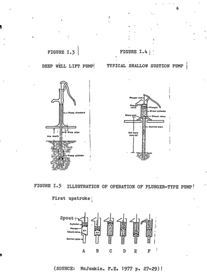
roughly separated by function into three parts (Figure 1-2): (1) the
pump stand assembly on the well; (2) the connecting assembly which
connects the above-ground components and the below-ground components;
and (3) the cylinder assembly in deep-well lift pumps (Figure 1-3) which
is located below the ground in contact with the water. In shallow well
(Figure 1-4) the cylinder assembly is in the body of the pump above
ground.
According to the location of these three parts, wells are divided
into two categories, deep wells and shallow wells. In deep wells, the
three parts are separate from each other (Figure 1-3). Deep well pumps
are called "lift pumps". In shallow wells the connecting-rod and
cylinder assembly may be located in the pump stand (Figure 1-4). These
are called shallow well "suction pumps".
Principle of Handpump Operation
Figure 1-5 shows a hand-operated, shallow-well suction pump. The
pump design includes a valved plunger which reciprocates and a
check-valve within the pump stand assembly. The following eight steps outline
the operating procedure of this type of pump.
1) The pump is primed by the first upstroke. When the plunger is
raised a vacuum is produced under the bottom surface of the plunger in
the cylinder. In the well, the atmospheric pressure on the water is
greater than the air pressure on the water in the suction pipe.
O 2 O US z z O u a O Z _1 >-o 03 S to < m S < CAP PUMP STAND SPOUT STAND BASE a PUMP 2 CYLINDER Ui en w < HANDLE
S
DPOP PIPE PUMP RODCA£
PUMP. ROD
DROP PIPE
SUCTION CHECK VALVE CAP TT~n CAP DISCHARGE CHECK VALVE CUPS tni CYLINDER
(SOURCE: McJunkin,F.E. 197?
Any d«pth
Pump standard
Drop plpa
__ ..„,._ -Pump cylinder
^\^^
Plunger rod-*
.^
piung.f — girn \
valve 34p5p""'""S"
ijr^j*-Brass cylinder
Check valve
Not more
Ihan22'
i
•^ Suction pipe
D
-i=l^
FIGURE 1.5 ILLUSTRATION OF OPERATION OF PLUNGER-TYPE PUMP
First upstroke
SpOUt'-5X"|
Cylinder _«. Plunger Check valve
¥ 7
Suclion pipe
B
^
D
f
F
cylinder, the plunger stops and the check valve closes due to its own
weight. Therefore the air stays in the cylinder.
3) During the downstroke, air is compressed between the plunger and
the check valve. When the air pressure becomes greater than the
atmospheric pressure above the plunger and the weight added to the valve
and plunger then the valve opens allowing air to escape to above the
priming water (Fig. 4B).
4) The second upstroke has the same effect as the first. Air and
water rise higher as the upstrokes and downstrokes are repeated until
the water from the well fills the cylinder (Figure I-5C).
5) With the next downstroke, the plunger and valve move down toward
the bottom and since water cannot be compressed the valve opens (Figure
I-5D).
6) As the plunger reaches the cylinder bottom, it stops and the
valve closes, keeping the water within the cylinder (Figure I-5E).
7) On the following upstroke, water is brought out through the
spout. At the same time water in the well is forced by the vacuum up
towards the cylinder (Figure I-5f).
Rate of Discharge
For a single acting reciprocating handpump, the theoretical rate of
discharge is the product of the cylinder volume (V) swept by the plunger
during its upwards motion and the number of plunger pumping strokes per
Figure 1-6 shows the relationships of these variables.
During the pumping action, the plunger changes direction and the
values do not always close instantly. There is also leakage between the
plunger and the cylinder wall as the plunger moves up and down. In
general this leakage results in the actual discharge of the pump being 5
percent to 15 percent less than the theoretical rate of discharge.
Energy Requirement
The power or rate of work is expressed as below.
P = QH/e
if
Q is the rate of discharge in liters per minute
H is the pumping head in meters
e is the pump's mechanical efficiency in decimal.
Therefore:
Power (in HP) = QH/4569e (2)
Human Power
The power capacity available from a human being varies from
individual to individual, the location, and the length of the working
period. Table I-l gives the value of man generated power. The average
adult human being can develop between 0.08 to 0.10 horsepower (60 to 75
watts) 8 hours per day and 48 hours per week. Also, for people who are
in poor health, malnourished, short stature or old, the value should be
PlunQvf .
" 11
S :: Stroke LanQt h
.- * . Low*r Limit of SIrok*
(SOURCE: McJunkin.F.E. 1977 P. kk)
TABLE I.1
MAN GENERATED POWER
ACE OF MAN USEFUL POWER BY DURATION OF EFFORT (in H.P.)
Yc^ars 5 min. 10 niln. 15 min. 30 min. 60 min. 480 min.
20 0.29 0.28 0.27 0.24 0.21 0.12
35 0.28 0.27 0.24 0.21 0.18 0.10
60 0.2A 0.21 0.20 0.17 0.15 0.08
Modified from Krendel (1967).
handle movement that does not allow many muscle groups to contribute to
operating the pump will also reduce the value.
It is generally accepted that the average adult human being can
offer 0.08 to 0.10 horsepower (60 to 75 watts) working for a long term
work period. For short bursts of energy the power developed may be ten
times as much as this (Stern, 1983).
If assuming a handpump has a typical mechanical efficiency about 55
percent and people can develop 0.10 HP, equation (2) becomes
QH = 251.
That means at a head of 15 meters the discharge rate Q would be about
16.7 liters per minute.
PROBLEMS WITH HANDPUMPS
The first problem is that there are insufficient handpumps. It is
the task of the 1980s, the International Drinking Water Supply and
Sanitation Decade, to provide 9.5 million pumps to people in rural areas
in developing countries.
Handpumps themselves have problems. The traditional cast iron
handpumps are not durable; usually they are hard to install, to operate,
and to maintain. The handle assembly especially is not durable, and a
field report from India specifies that 70 percent of.the pump breakdown
was due to faulty or broken handles (Janssens, 1983). The cup seals
frequently must be replaced. Another problem of the pump itself is that
^
local village.
Up until recently service to pumps was the job of trained mechanics
who covered their area in trucks. In developing countries there is a shortage of trucks, fuel, spare parts equipment, and even of skilled
manpower. The results of these shortages are a high percentage of
inoperative pumps. =
The cost of maintaining the hand pump is a deterrent to developing countries. In order to keep the pump working, the average maintenance
cost is estimated at about $400 per pump per year. In some instances
maintenance costs consist of 85 percent of the total cost of the rural water supply (World Water, December 1981c).
The Water Decade is promoting the VLOM concept. VLOM means Village Level of Operation and Maintenance. The ideal is for all routine care of the handpump to be done by a village caretaker with minimum tools and equipment.
INFORMATION ON HANDPUMPS AND THEIR PROBLEMS
Information on handpumps may be found in three sources:
1) Laboratory test reports and technical journals;
2) Field test reports;
3) Manufacturer advertisements and specifications.
The identification of many pumps may be found in books and journals, but
Researchers all over the world are studying the cost-effective pump
with VLOM concept. For the past decade, innumerable handpumps have been
manufactured around the world. The pump manufacturers always promote
their own products. What has not been considered often is that the
conditions in the field are completely different from the indoor
laboratory tests.
In fact, handpumps installed in developing countries have
encountered many problems in operating and maintenance. One can easily
find literature describing individual pumps. Now what people need is
readily available information that compares the individual pumps and
their features to each other. But the information that compares the
pumps to be used in different countries is not available.
Of course, all the designers and manufacturers think that their
product is the best. Therefore, in the country different designs and
manufactured pumps have been installed, but no one knows which one is
the most appropriate. Those working in the 'Vater Decade" will be
anxious to know which pumps are best to meet certain conditions in
different countries, but there are not any such articles to provide the
information.
THE OBJECTIVES OF THE REPORT
The objectives of this report are to provide comparative data on all
of the existing handpumps that may be obtained and installed by
1) How easy is it to obtain all of the raw material to manufacture
the pump? Is the pump simple to manufacture? Can the pump be
manufactured locally?
2) How easy is the pump to install? Does it need lifting tackle?
How many people are there needed to install it?
3) How easy is it to keep the pump in working order? How often
must maintenance be performed? Which parts must be replaced
periodically? Which parts are likely to break or fail?
4) How expensive is it to purchase and to operate?
From all these aspects it will be possible to recommend specific
hand pumps to match the conditions found in a country. Finally,
criteria for an ideal pump are proposed and improvements of handpumps
suggested.
SOURCES OF REFERENCE
The major reference base consists of reports from UNDP, WHO, UNICEF,
WB, Consumers' Association Testing and Research Laboratories, and
technical journals such as World Water and Waterlines, as listed in the
References.
LIST OF HANDPUMPS
Pumps are listed in categories in order, with those for which the
most information is available being listed first. Appendix A is a
«#
^#
(see Chapter IT) Volanta Pump, Moyno Pump, Maldev Pump, Korat Pump,
New No. 6 Pump, Kenya Pump, Petro Pump, Jetmatic Pump, Abi-Vergnet
ASM Pump, Nira AF76, Rower Pump, India Mark II Pump, Consallen
Pump, Mono Pump, Hydro-Pompe Vergnet Pump, Battelle/AID Pump,
Kangaroo Pump, Kardia Pump, Turn! Pump, Waterloo Pump, Dempster Pump, ABI Pump, and Monarch Pump.
2. Pumps with description and field experience: (see Chapter III)
Blair Pump, Plastic Pipe Pump, Bamboo Pump, Deplechin Pump,
Shln-yanga Pump, Marumby Pump, and Lucky Pump.
3. Pumps with description and laboratory testing: (see Chapter IV) Ethiopia BP 50 Pump, Nepta Pump, Vew A18 Pump, Fungmaq Pump, Bandung Pump, Sumber Banger Pump and Drogon No. 2 (D) Pump.
4. Pumps with field experience: (see Chapter V) Bangladesh Deep-Set Pump, Tredle Pump, ESW-81 (82) Pump, Local Experimental
Shallow-Well Pumps (Papua New Guinea), Clayton-Marks Pump, Bourga Pump and
Sarvodaya Pump.
5. Pumps with laboratory testing and manufacturer information: (see
Chapter VI) Godwin W1H51 Pump, GSW1205 Pump, and Climax Pump.
6. Pumps with manufacturer information: (see Chapter VII) Duba Tropic
Pump, Stewarts Pump, Lioyds Pump, SYB-100 Pump, SWN81 Pump, Sholapur
(Mission or Jalna-Type) Pump, Bangalore Pump, U.S.T. (KUMASl) Pump,
Pompe a Balancier Pump, Pompe a Pieds Pump, and JAMHP Pump.
7. Pumps with name: (see Chapter VIII) Maya No. 6 Pump, Tara Pump,
Hand Driven Ejector Pump, Royale Pump, Africa Pump, Majestic Pump
Introduction to Description Handpumps Laboratory Test Data
In order to improve the quality of life in developing countries, the
experts who are working for the International Drinking Water Supply and
Sanitation Decade (IWSSD) believe that clean drinking water and
sanitation could have more impact than any UN program ever conceived to
reduce human suffering. Even though in the developed world handpumps
have almost become antique curios, in the developing countries of Asia,
Africa, and Latin America there is new interest in using handpumps.
Since the 1960s high speed water drilling and light weight PVC pipe were
used for community water supply wells. Installation of handpumps in
wells is the simplest and cheapest way of supplying water to rural
areas. Thus, handumps will play an important role during the Water
Decade.
Most handpumps used in developing countries are imported from the
developed world where the pump is designed to be used by one family once
each day. They could not stand the severe use required in developing
countries, working continuously every day for 6-7 hours. Under these
conditions conventional handpumps are unreliable and have many
shortcomings, such as: low efficiency requiring greater pumping effort,
low discharge, frequent breakdowns, and poor seals allowing
contamination from the ground surface. Imported pumps are expensive and
also have problems because spare parts must be bought from foreign
countries. In the 1970's thousands of villages were provided with
No. 2, 1983)
In response to these problems, studies have been conducted by
researchers around the world such as; the World Bank, United Nations
Development Program, the United Nations Childrens' Fund, the World
Health Organization, the United Nations Environmental Program, the
United States Agency for International Development, and related
organizations. They were especially interested in handpumps with simple
construction and low-cost which can be manufactured locally using local
materials and commonly available skills and techniques. The pumps
should also be able to stand heavy use or misuse, with low maintenance,
and can be repaired by the local villagers.
In 1966 the United States Agency for International Development (AID)
contracted with the Battelle Memorial Institute - Columbus Laboratories
to develop a dependable handpump suitable for use in rural water
supplies in developing countries.
In 1977 the Overseas Development Administration of the United
Kingdom was anxious to know the following data:
1) What kinds of problems are there in the field where handpumps
were working.2) A comparison of pumps to decide which is better for use in
developing countries. •
i
3) The technical information of pump performance, manufacturing
#
First they tested twelve different pump designs chosen to repre¬
sent as many design types as possible. They were all deep-well pumps
including traditional and newer designs which can be operated by hand
or foot.
The pumps selected from eight countries are shown in Table IX-1.
These data are included in their final report of January 1981 (Overseas
Development Administration Handpumps Laboratory Testing Final Report,
January 1981).
In ]980 the World Bank with UNDP funding commissioned the Consumers'
Association Testing and Research Laboratories to continue work on
handpump assessment, in cooperation with the beginning of the
International Drinking Water Supply and Sanitation Decade in 1981.
Three batches of six pumps selected from 16 countries were tested.
This report gives these results, from the laboratory testing of
handpumps from the Rural Water Supply Handpumps Project. This infor¬
mation comes directly from their publication; "Laboratory Testing
of Handpumps for Developing Countries" (World Bank, 198A) (see
Table IX-2 and Table IX-3).
Introduction to Field Experience with Handpumps
At the end of 1981 UNDP/World Bank decided to field test the pumps
in 20 countries: Kenya, Tanzania, Malawi, and Sudan in East Africa;
Ghana, Ivory Coast, Niger, Upper Volta and Mali in West Africa;
Bangladesh, India and Sri Lanka in South Asia; Malaysia, Thailand,
Individual handpump field experiences were published in technical
journals such as World Water, Waterlines, Civil Engineering/ASCE,
African Water and Sewage and United States Agency for International
Development Handpump program in the individual countries.
This report contains several parts, they are:
1) pumps with description and field experience
2) pumps with field experience
3) pumps with description and laboratory testing in CATR
4) pumps with field experience
5) pumps with laboratory testing in ODA and manufacturer information
6) pumps with name.In this report all the basic information is from field tests or
technical journals. My contribution is in reviewing the existing
handpump laboratory tests and experiences in developing countries, and
giving my opinion about the advantages and disadvantages of the
This chapter includes information on all pumps with laboratory
testing and field experience. They are in two groups. The test data
were available only for the first group. The first group was tested by
Consumers' Association Testing and Research Laboratories in England.
The second group includes pumps tested by three different laboratories:
Overseas Development Administration; Consumers' Association Testing and
Research Laboratories in England; and Battelle Memorial Institute,
Columbus Laboratories, in America.
PUMPS WITH TEST DATA PRESENTED HERE
Field
Testing Countries Upper Volta
Ivory Coast, Ghana, Upper Volta, Nicaragua
Kenya, Tanzania, Malawi Thailand, Philippnes,
Sudan, Ch ina Thailand Korat 608A-1 Deep Thailand
Bangladesh New No. 6 Shallow Bangladesh, India,
Sri Lanka
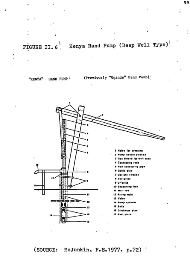
Kenya Kenya Deep
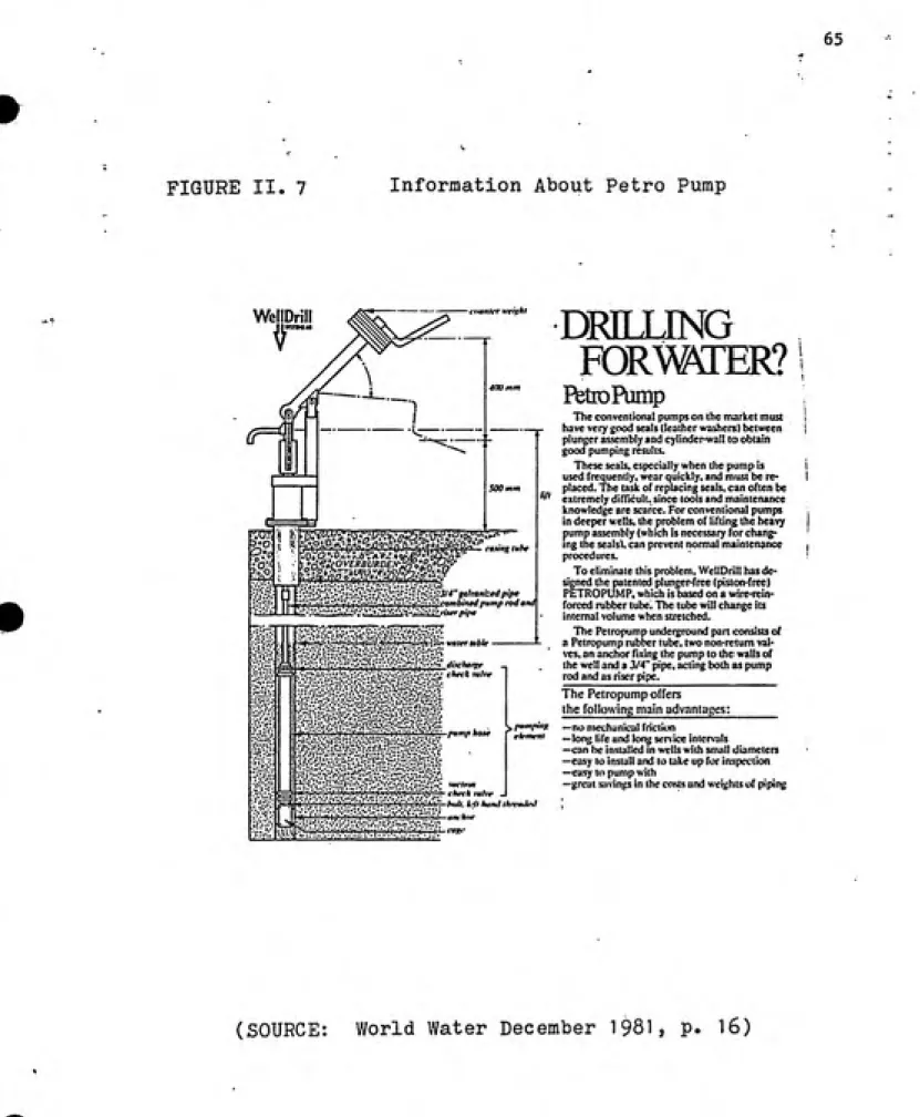
Sweden Petro Deep Kenya, Sudan
Deep or Country of Ori
g.in Name Shallow
Holland Volanta Deep
USA, Canada Moyno Deep
Ivory Coast, France Abi-Vergnet ASM Deep Upper Volta, Mali, Ivory Coast
Finland Nira AF76 Deep Tanzania
Bangladesh Rower Shallow Bangladesh, India,
Sri Lanka, China
4>
ͣ
Ynlanta Pump Description
The Volanta pump is niade in Holland and in Upper
Volta. It uses a heavy fly wheel to generate a
conventional reciprocating action but in many other
ways is unconventional. *
Two types of cylinder were supplied; these are
referred to hereafter as cylinder types 1 and 2.
Type 1 had a machined nylon cylinder body and a
stainless steel plunger, with a turned bronze
sealing ring. Type 2 had a glass reinforced
plastic cylinder body and a long, close-fitting
stainless steel plunger, with no other seal.
Connection between the above- and below-ground
parts was by cable In the samples supplied for f
testing, though the manufacturer now supplies J
steel rods. Thf complete cylinder is designed to
be extractable from the well, using the connecting
_cable or rods, without the need to remove the uPVC
rising main.Above ground the pumpstand is unusually large.
For testing, the pumps were supplied v/ith
supporting steel framework, but in field
Installations the crankshaft would be supported by
a concrete pillar as shown, or by a fabricated
steel box. The pump stroke is adjustable to
compensate for operating depth.Materials of Construction
Above Ground Assembly
COMPONENT
MATERIAL(S) Crankshaft
Crankshaft Bearings Flywheel and Handle Connecting Rod
Spout
Cable
Crosshead Assembly
Cylinder Type 1 Cylinder Type 2
COMPONENT MATERIAL(S)
Cylinder Body Plunger Sealing Ring Foot Valve Body Valve Poppets
PA 10 nylon Stainless steel
Bronze
Stainless steel. Moulded rubber
Volanta PuMO (both types)
m-^
Steel
Standard solf-allgnlng plummet blocks
Steel
Steel tube with standard self-aligning ball
races at each end
Steel tube, hot dip galvanised
Steel, contra-wound to resist twisting
Stainless steel shaft, steel fittings, with
PA 10 nylon guide ring
COMPONENT MATERIAL(S)
Cylinder Body Plunger
Foot Valve Body Valve Poppets
Epoxy bonded glass
ͣ
WEIGHTS & MEASURES
Weights
Pump stand : 76.3 kg Cylinder type 1: 9.4 kg Cylinder type 2: 10.0 kg Drop Pipe (per m): 1.7 kg
Dimensions
Nominal cylinder bore (both types): 50 mm Drop pipe size: 3.0 inch Outside diameter of below-ground
assembly: 101 mm The pump stroke, and therefore the nominal volume per stroke, are variable depending on depth,
(see pump performance)
Manufacturing Techniques
Above-ground assembly Steel fabrication
Machining of steel and plastic
Concrete craft
Manufacturing the pumpstand demands basic skills in machining and steel fabrication. It may be suitable for manufacture in some developing
countries.
Cylinder Type 1 Machining of metals and plastic Rubber moulding.
Welding of stainless steel
The cylinder is machined from a solid billet of nylon, the stainless steel plunger and bronze sealing ring must be machined to close tolerances and high standards of finish.
Cylinder Type 2 Fabrication of glass reinforced plastics Machining
Rubber moulding
The cylinder body is fabricated from epoxy resin reinforced with glass fibres. Achieving a consistent high quality In the finished component Is
likely to demand considerable skill and experience. The plunger must be machined to a close tolerance and with a good standard of finish.
Ease of Installation, Maintenance and Repair
l-^ise of Installation
The most tlrae-consumlng Installation Job is likely to be corislrucllng the concrete plinth. In other respects Installation Is strnlgliLforward and will not require lifting tackle. It Is necessary to adjust the pump stroke and the length of the connecting rod to suit the depth of water in the
well.
Ease of Pumpstand Maintenance and Repair
The most frequent maintenance operation is likely to be tightening the gland at the top of the connecting rod, but this Is a very simple task. Indeed all pumpstand maintenance should be straight forward, requiring only a few
spanners and simple hand tools.
Ease of Below-ground Maintenance and Repair
Both types of cylinder are designed to be extracted from the well on the end
of the connecting assembly without the need to remove the rising main. Our experience suggests that the rods which the manufacturer now supplies are
POMP PERFORMANCE Volume Flow. Work Input and Efficiency
The description of the method can be found in the Test Procedure.
Examples of performance graphs are given in Appendix II.
Rotating crank arm showing positions
able to be selected
for operation at different water depths.
W -fauMJt ffl
*"»— _ T'^e manufacturer's recommendations for the crnnk position were as
Position 1
Depth (m) Crank throw (mm)
Position selected
for test
< 15 15 - 21 21 - 30 30 - 40 40 - 55 55 - 80 310 240 190 150 120 100 7m Users 25m 45m
Cylinder Type 1 HEAD 7m 25m 45m
: Pumping Rate
(rcvs/min) 18 24 26 34 19 27 35 21 27 33 37
Vol/revs (litres) 0.61 0.61 0.60 0.58 0.33 0.33 0.33 0.23 0.25 0.25 0.25
Work lnput/rev(J) 140 U9 99 92 140 132 136 157 156 181 181 Efficiency (Z) 29 35 41 43 57 61 59 65 69 60 60
;ylinder Type 2 HEAD 7ra 25ra 45m
Pumping Rate
(revs/min) 23 31 37 22 29 37 20 28 36
Vol/rev (litres) 0.61 0.61 0.61 0.32 0.33 0.34 0.24 0.25 0.25 :. Work input/rev (J) 128 120 118 148 162 151 144 180 190
Efficiency (Z) 32 34 35 53 49 54 73 59 58
NOTE: It wns difficult to accelerate the llywheel .uul Nu.stain the target
operating speed within the nl.ne revolution limit of the potentiometer. See the manufacturers comments in the verdict.
ENDURANCE A detailed description of the endurance test method can be found In the Test
Procedure.
General Comments
The cable originally supplied broke several times in the early stages of the endurance test. The type 2 cylinder was replaced by the second sample after
24 hours because debris from a broken cable had dropped into the cylinder causing a deep score in the bore. Springs were introduced into the cable to represent the inherent elasticity of 45 m of cable - the actual cable length in the test installation was less than 5m- but these fatigued very rapidly. The manufacturer supplied thicker cable of galvanised steel rather than Stainless steel, and this was used to replace the original cable as necessary
when the latter broke.
Because the stresses in the short cable used for this test were not considered
to be entirely representative of conditions in the field, cable breakages have
not been highlighted as purap failures. However, failures of components
related to the cable, but not the cable Itself, are noted.
For performance testing the length of the above-ground connecting rod was
adjusted to the 7 m depth setting. This enabled the pump stroke to be adjusted for operation at 7, 25 or 45 m. This caused premature wear in the wellhead
gland, and for the endurance test it was necessary to adjust the connecting rod
for the stroke specified for 45 m.
The upper cable fixing point broke in both pump types, and at the lower fixing point several cable thimbles broke up as a result of localised
stress. On one occasion, debris from a broken thimble dropped into the type
2 cylinder causing the plunger to seize in the bore. Conventional steel thimbles were replaced by turned acetal pulleys and the method of attachment
was modified to improve the distribution of stress. The modified components
were still in good condition at the end of the test.
At the 3000 hour inspection, the type 2 cylinder could not be extracted from
the taper seat in the rising main. Kieselguhr, which was added to the water
for the third 1000 hour stage, had accximulated between the cylinder body and the rising main, and the cylinder was 'sand locked'. It was released by removing the lower section of rising main, but In the field this would entail
removal of the complete below-ground assembly.
Leaking joints in the rising main for the type 2 cylinder could not be
cured by conventional pipe sealing compounds. However, worm-drive hose
dips applied around the outside of the joints ensured an adequate seal.
Breakdown Incidence R_„„i,H,^uno =.-<. ohntm in k«ih fvnn_
Cylinder Type 1
Hxirs '1027 2094 3125 4164
0 1 2054 1 7R78
1 3451 3699 1
Inspection 1 1 1 Inspection | 1 1 & fuU pel- Inspection & | Inspection & volime flow | 1 Inspection
fornance test volune flow | & volune flow 1 1 1 (. full
1 1 1 Cihle top perfonnance
CsUle tup OihLc tlilofale 1 fixing test
flxii« point broken at | point
..
bnakcn 1
1
bottai 1 ccnnnction |
broken
Cbble tMable able thiahlc
broken at brulcoi at l»th
botboB oonrwction top and bottim
connoctlanB
-icpLaoed by turned
acetal pulleys '",
1/
Cylinder Type 2
Hours 0
1027 2094 3125
4164
2931 3ZM 3«10
Inspection
& fuU
performance
test
Inspection & Inspection & volui£ flew . volune flow
FIHAL INSPECTION Cylinder (a) (b)
Valves
Pumpstand
Filter
Corrosion
Inspection & | | Inspection &
volune flow | | full
per-I per-I j formunce test
I leaking Joints | I in rising main |
CiUe top I fixing point I broken |
cylinder 'sand-lodced' In rising
naln
Qlile thlnlile
brolcen at bottoa
oamecClati
De1x*18 from
broken thjidile on bottoa oonaectlm caused plitigpr to
seize — tfaiiiUe
replaced fay turned acetal pulley
Cylinder bore pitted, even in the unswept areas
Plunger scratched, but otherwise no perceptible wear
Some wear on plunger and foot valves, but otherwise
in good condition and still serviceable
Well head gland leaking slightly when pump stationary
but satisfactory when operating pump
Thickly coated with sand and general debris but
still working
Some rust on cylinder end cap
Estimated total amount of water pumped in 4000 hours 1.9 million litres
1
VERDICT
The Volanta pump with the two types of cylinder as supplied for this test
proved to be unreliable in use.Users found the pump difficult to start and maintain a steady rhythm. In
the field with more time available there will be an opportunity for users to
develop a better technique. Nevertheless it is recommended that
consideration be given to a simpler pumpstand using a conventional lever arm
at a considerable cost saving.
Many problems were encountered with the method of fixing the cables and some
months after starting this test, programme the manufacturer decided to
discontinue the type I cylinder.assembly.
The pump has now been substantially modified In response to the results of
these laboratory tests and to Information from the field. Steel rods with
hook-and-eye connections are now used in place of cable.
The type 1 cylinder Is no longer In production and It Is Interesting to note
that In the tests it performed generally better than the type 2 cylinder.
If the modifications prove to be successful In future tests, then the
Volanta may be suitable for community water supply In developing countries.
It also has considerable potential for local rn.inuf.Mture providing adequate
EXPERIENCE WITH VOLANTA PUMP
According to Field Trial Sites Chosen in 20 Countries (World Water
Journal, February 1983c). The Volanta pump to be field tested in Upper
Volta, West Africa. i
Volanta pump was manufactured in Upper Volta and has been installed
in Badie 180 km southwest of Ouagadougou, Upper Volta. This pump is
very easy to maintain. In order to inspect or repair below-ground
components, the flywheel has to be detached from the down-shaft
fittings. The piston is mounted on the 3 meters long interlocking rods.
These can be removed or installed within 15 minutes.
In Upper Volta, the Volanta pump project includes an education
program dealing with health and proper use of a village water supply in
addition to maintenance and installation.
ADVANTAGES AND DISADVANTAGES
Advantages
The major advantages are two. One is the flywheel and pedestal are
set at the side of the well. The below-ground components can be
withdrawn without moving the pump stand. Another is that by using 3
meters length interlocking rods, it is quick and easy to dismantle the
pump. If labor is impossible, it can be belt-driven by a diesel motor.
Disadvantages
It was mentioned that the considerable skill, experience and quality
control in manufacturing the pump is required. These rigid standards
$845, that cannot be afforded by villagers without a government subsidy.
The flywheel is potentially hazardous to people especially to children because of the inertia. The rotating crank arm could be
dangerous too.
The big wheelfly is difficult to start and maintain at a steady rhythm. It is very difficult to reconcile to these conflicting requirements of safety and ease of operation in a flywheel-operated
FIGUI II. 1
:niorffiation About Volanta Hand Pump
VOLANTA
HAND PUMPS
Fabricated by JANSEN-VENNEBOER
Dutch water engineers, in close
co-operation with aid agencies,
developed a completely new type
of handpump.
This pump fulfils following
requirements:
- Low operational and maintenance costs
- Operating from shallow wells as
well as 80 metres bore holes
- Easy to drive, also for women
and children
- Capacity almost 2000 l/h.
- High efficiency in operation
- No lifting equipment needed This village-level-operation and maintenance handpump will solve your drinking water problems in
the rural areas.
The pump is easy adaptable to other modes of energy.
(SOU 2cv •
/orld V/ater December 1981, p. 31)
Some manufacturers have a/ready begun to respond to the UN challenge to produce a VLOM pump. This Volanta pump from Insto of the Netherlands uses a cable to drive the cylinder instead of screwed rods. As a result, the manufacturer says, installation or dis¬ mantling is quick, simple operation for one man with no special tools. Flywheel operation can be handled by a five-year old child, and the pump is said to be suitable for depths of
4-100m.
World Water understands that Danish
manufacturer Crundfos is also working on a VLOM pump design, but the company says it has no news for publication yet.
...Still going strong..
V^i
blanta
A reliable solution
for safe drinking water.
the pump that lasts!
o Universally applicable o Easy to operate 0 Easy to install
o Simplicity
of repair o Long life
Ask for detailed
information:
JansenVenneboeri
P.o!box12,8130AA Wijhe
The Netherlands
Tel. 05702-2525; Telex 49418
Visit us at Amsterdam Aquatech Stand No E410
w
Hoyno Puip
^y V
J_ IB,
•
rpo
Movno Pump Description
The Moyno pump tested was made by liobblns and Myers In the U.S.A., Is a positive displacement pump,
which has a plated helical steel rotor within a double-helical elastomerlc stator. The pump rods
rotate Instead of reciprocating up and down. The pump is operated by a pair of rotary crank handles, driving a gearbox and one-way clutch. The pumpstand iB very robust, of all-steel construction. The twin handles make the pump suitable for operation either
by one or two people. Materials of Construction
COMPONENT MATERIAL(S)
Pumpstand column Pump top (gearbox)
Handles Bearings Gears Rotor Stator Foot valve Drop pipe Pump rods
Fabricated steel, galvanised
Cast steel
Cast steel
Proprietary taper roller bearing!
Mild steel
Steel, hard chrome-plated
Moulded elastomer in steel tube Gunmetal with brass strainer
Galvanised steel Galvanised steel WEIGHTS and MEASURES
Weights Pumpstand
Cylinder assembly Pump rods 48.0 kg 16.0 kg 1.2 kg. Dimensions
Drop pipe size:
Outside diameter of below-ground assembly:
Pump rod diameter:
per metre 1.25 inches
75 mm
0.5 inches
Manufacturing Techniques
The manufacturing techniques required to make the pump are listed
below:-Above-ground Assembly
Iron and steel foundry
Steel fabrication
Complex machining
The pumpstand demands advanced manufacturing techniques and skills, not be suitable for manufacture In a developing country.
It would
Below-ground Iron foundry Assembly Gunmetal foundry
Simple m;ichlning Hard chrome platinR
Specialised processes (pumping tUemont)
The pumping element demands advanced and specialised manufacturing techniques
and a high degree of skill.
Ease of Installation, Hnlntonancc and Repair Ease of Installation
A die and diostock. for threading the pump rod, to>;»!ther with <*l:imp.s" ;ind lioxagon keys were supplied with the test samples.
Ease of Puinpstand Maintenance and Repair
Frequent attention to the pumpstand Is unlikely to he required. A broken handle I
could be replaced In the field, but internal repairs to the gearbox assembly may '
demand workshop facilities.
Ease of Below-ground Maintenance and Repair
Frequent attention to the below-ground assembly Is unlikely to be required.
However, any repair requires removal of the complete below-ground assembly, and
if the pumping element is faulty It must be replaced as a unit. In general,
this pump requires an exchange rather than a maintenance routine.
PUMP PERl^'ORMANCE V
Volume Flow, Work Input and Efficiency
The description of the method can be found In the Test Procedure.
HEAD 7 m 25 m 45 m
Nominal pumping
rate (rev/min) 30 40 50 30 40 50 30 40 50
Vol/rev (litres) 0.23 0.23 0.23 0.20 0.20 0.20 0.15- 0.15 0.16 Work input/rev (J) 130 144 140 139 152 166
Efficiency (%) 11 10 11 35 32 29
195 209 198
34 31 36
ENDURANCE
A detailed description of the endurance test method can be found In the Terms of Reference.
General Comments
The pump was tested at 40 revolutions per minute at a simulated head of 45
metres.The Moyno failed once in the 4000 hour test programme, after 3178 hours. A
rubber block Is fitted In the bottom of the cylinder to prevent the rotor
Striking the base of the cylinder during Installation. Although when first
Installed there was a clearance of 30 mm or so between the bottom of the rotorand the block, the block had worked Its way up the cylinder bore and fouled
the rotor, making the pump very difficult to turn. It was replaced In the
correct position and the problem did not recur.
At the end of the test, the pump was generally in very good condition, with
little corrosion. Wear was confined to the clastomerlc stator which had been scored in several places by sand, but this was insignificant.
Breakdown Incidence
Breakdowns are shown in bold type.
Hours: 1072 2044
I 3060 4063 3178 I Inspection and full performance test Inspection and volume flow FINAL INSPECTION Pumpstand Cylinder Assembly Inspection and volume flow
I Rotor I Seized I Inspection and volume flow Inspection and full performance test
In good condition throughout
(a) Rubber stator grooved by sand particles,
but still serviceable
(b) Steel rotor In good condition, highly polished
(c) Considerable quantity of sand In foot valve, though still working
Corrosion No significant corrosion, though paint flaking off cylinder housing
Estimated total amount of water pumped In 4000 hours ... 1.5 million litres.
VERDICT
A robust pump, in good condition after 4000 hours of endurance testing. The rate of delivery was low, and the pump was hard work to operate at first, though it became slightly less hard with further use. Although generally
t
t
Experience
In Haiti, West Indies the pump is installed to withdraw the water
from 45.5 m depth of well. In Ghana, West AFrica they ordered 500 pumps
after using and being satisfied with the way the pump operated. The
average depth of the Ghana well was 2.5 m (test pump in Ghana). In
Togo, West Africa even a child could pump water from a depth of 14.8 m
without hard work. In Jakarta, Indonesia the early model pump worked
for over three years without any maintenance or repairs being needed.
ADVANTAGES AND DISADVANTAGES Advantages
The mechanism is totally enclosed in the pump stand.
Since the bottom of the rotary part must be immersed, no priming is
required, no contamination can occur.
As there is only one moving part in the pumping elements, there is
no potential of contaminating the water in the well.
There is a brass check valve with a self-cleaning strainer in order
to keep large particles of silt or sand from entering the pump.
The pump can be converted to alternate power sources such as
electric motors and gasoline engines.
Disadvantages
Since the bottom of the rotary part must be ionersed, the pump
cannot be used as a suction pump.
If the pumping element is faulty, the whole element must be
t
Most of the effort must be supplied by the arms and shoulders only;smaller users with limited reach could not maintain a smooth circular motion of the handles.
The rate of delivery was low and expensive.
•
FIGURE II. 2 Infor'Tiation About Koyno Hand Pump
•
GeiTs —
laLjHSear Box
iJ ;Oibcharge
Pump- Stdnd , -5,
ͣ
^f'crf'Jii
<>lVi3Ki
- Rotor s.5> •' t.Stator
Brass
Check Valve-—
"Seif-Cieaning
Straine Drawing shov/s the simple _^.9|ements of the Robbins &
"'lyers hand pump.
This pump replaces water from an irrigation ditch in Haiti. Depth: 45.5m (148 ft.
.iJf.
%
^lEfpos^a^^tnent'; o' fh
^^Cp'ufnpVre'cfef.iqned to
P^^reventpilfering or
''^S vandalism;-;*
V^t''^^'^ ^^
One of 10 test pumps m
Ghana which led to an
order for 500 more. Average depth: 21.5m (70 ft.).
A child in Togo
demonstrates the ease of
pumping water from a depth of 14.8m (50 ft.'
Early model pump near Jakarta, Indonesia. No maintenance or repairs in over three years.
', ()^ p I >-| 3 j H p ("over)
•
•
Maldev Pump Description (Malawi Pump)
At present, the Maldev consists of an above-ground assembly only. The pump was tested with a prototype below-ground assembly designed by Ken Mcleod and later with a Funynaq cylinder assembly.
The Maldev pump head was designed and made in Malawi, initially with ODA assistance, for use with
conventional reciprocating deep-set cylinders. It
Is fabricated from steel sections and the pedestal ' Is Intended to be concreted-in at the well head. I The height and dimensions of the mounting flange
are identical to the India Mk II pump. The handle
bearings are sealed ball races. It is designed to allow a 2.5 inch diameter plunger to be extracted without the need to dismantle the pumpstand. The
handle is offered in various lengths to compensate for operating depth and cylinder size.
Materials of Construction
COMPONENT MATERIAL(S)
Upper body and cap
Handle
Bearings Hanger
Pedestal
Steel tube and plate Steel bar and plate
Sealed ball races
Steel
Steel tube and plate
WEIGHTS and MEASURES Weights Dimensions Pumpstand complete: Not applicable 51.1 kg Manufacturing Techniques
The manufacturing techniques required to make the pump are listed below:
Simple but heavy steel fabrication Skilled welding
Simple turning, drilling and threading
The Maldev has been designed for manufacture in a developing country.
Both the fabrication and machining are straightforward, and no specialised
processes are required. However, considerable skill in welding is demanded, and careful quality control is essential. It is suitable for manufacture in developing countries, but potential manufacturers must be carefully
selected.
Ease of Installation and Maintenance
Ease of Installation
t
Installation of the pumpstand is generally straight-forward. Lifting tackle
will also be required to cope with the weight of the below-ground assembly
unless plastic rising main is used. The pedestal is concreted in at the
wellhead around the well casing and the top of the pumpstand assembly can be
installed with the handle pre-assembled. Some care Is needed to ensure a
satisfactory water-tight joint between the rising main and the pumpstand,
but otherwise assembly is straight-forward and requires only basic, skills.
Ease of Pumpstand Maintenance and Repair
The pumpstand is generally robust and unlikely to require frequent
maintenance, however more frequent attention may need to be given to the
joint between the rising main and the pumpstand to keep it watertight.
•
t
PUMP PERFORMANCE
Volume Flow, Work Input and Efficiency
The description of the method can be found in the Test Procedure.
HEAD 7 m
25 m 45m
Pumping Rate
(strokes/mln) 29 41 48 20 30 37 20 30 37 45 Vol/stroke (litres) 0.47 0.48 0.48 0.52 0.51 0.52 0.46 0.51 0.50 0.48
Work input/stroke (J) 53 55 59 179 185 193 253 271 268 273 Efficiency (Z) 60 59 55 70 67 66 80 82 82 76
These results were obtained from the jirototype head with an experimental
'McLeod' type cylinder as the below-ground assembly.
ENPURANCE
General Comments on the Pump Head
The pump was tested at 40 strokes per minute at a simulated head of 30 metres.
Several problems were encountered with the original seal between the rising
main and the pumpstand. After 2188 hours the rising main was not secure In
the pumpstand and slipped through the seal on each upstroke of the cylinder.
It was re-tightened but thereafter persistent leaks occurred until the seal
was replaced by the later type now supplied with the pump. Even then a
persistent slight leak remained between the rising main and the pumpstand
until the end of the test.
The original endurance test sample was not representative of current
production. One of the handle bearings broke up during the first 1000
hours. Subsequent, examination revealed that the ball race had l>een damaged
while being hammered into. Its housing. The endurance test was therefore
restarted using a newer pumpstand, to which the comments in this report refer
exclusively. This sample was tested using a Funymaq cylinder as the
below-ground part.
f
Breakdown Incidence
Breakdowns are shown in bold type.
f
ttKirs: 1021 2096 3J31 4137
0 1 1 1 1 1 2188 1 1 2«9 2426 2918 1 1 1 1 1 1 1 1 1 1 1 1 1 1 1 1 1 1 1 1 1 1 1 Inspection Inspection Inspection Inspection Inspection
Rlslog main
not secure
In pimpstand
Lsldng amnd rising vein inside puDpstand Final Inspection
1. Joint Slight leak at joint between rising main and pumpstand
2. Bearings Considerable free play in handle bearings
3. Corrosion No significant corrosion
Estimated Total Amount of Water Pumped in 4000 hours...5.0 million litres
t
VERDICT
A robust pumpstand but still requiring some development of the method of fixing the rising main, clearly designed to use appropriate manufacturing skills with VLOM in mind. Although capital-intensive manufacturing facilities are not necessary, strict quality control is essential to achieve a reliable product.
There is scope for reductions of both cost and difficulty of manufacture by
using plastic plain bearings rather than ball races in the handle and
hanger.
Polyacetal bearings have therefore been made for both these applications and field trials are in progress. Good preliminary results have been received
and further samples have been installed on heavy usage pumps to gain further
experience.
Once the principle has been thoroughly tested out successfully, changes can
be made to the design which will simplify the manufacture, and reduce the cost of this head.
t
•
In Malawi over last 15 years, almost all of the piped water projects
have used surface water to provide 302 of the country's needs. But
perennial surface water sources which can be tapped were severely
limited. As a result, Malawi has no choice except to develop
ground-water resources. Seventy percent of the rural population is served by
groundwater. It was estimated that by 1990 a predicted 5.5 million
people have to rely on their sole source of safe water - groundwater.
In an Upper Livulezi pilot project, experience with the handpump is
not the only advantage. There is also the organization which involves
the Malawi professional staff, who will manage the pump site with
outside technical assistance. For example, one professional on the
staff job includes organizing drilling rigs, well-digging teams and a
maintenance crew. He also goes through the villages, speaking with
villagers and local officials. Each village has two tasks; one is to help select a well location which is acceptable, and the other is to elect a village committee that will be in charge of handpump
maintenance.
The construction of a borehole or well is a very important factor in determining the performance of each handpump. In Livulezi valley
project:
FVC well screen and slotted casing with a hundred fold increase of ideal gravel pack material in diameter from 0.7 to 2.5 mm
were used to increase water entering the well, to stop sand
•
f
- The special pump head was designed so tat the connecting rods can be pulled out by two people without using winch in about 15 minutes.
Hinged rods are used for removing them by people without tools.
Injection moulded plastic foot valves and piston are used in
downhole components. So one spanner will be able to extract
damaged parts and to replace them easily and quickly.
Malawi pump heads and the components are made locally, and the
spare parts can be supplied locally. If the pump is broken, the
village caretaker will collect some money from the community to
buy the components from the local store.
The performance of Malawi pump installed in Malawi, south of
Tanzania, and other African countries such as Kenya and Sudan, and in an Asian country, Thailand, satisfied the needs of villages because the
pump gave a better flow rate and was easier to operate. The Malawi pump
used in the Livulezi pilot project is closer to the Village Level
Operating and Maintenance (VLOM) concept, as one man riding a bicycle
would be able to service several pumps at very little maintenance cost.
(NOTE: Malawi Pump also named Maldev, Afridev.)
ADVANTAGES AD DISADVANTAGES Advantages
The best advantages of the pump is using the hinged rods to remove
the connecting rods through the top of pump without removal of the pump
•
•
better mechanical advantage than a straight handle.
Users can use muscles from several parts of the body to make pumping
water easier.
Malawi pump and spare parts can be supplied locally.
Since villagers think of handpumps as their own property, they are
anxious to take care of them.
Users are better organized regarding handpump maintenance.
Disadvantages
Although the newly designed pump head is convenient for withdrawing
the below-ground components, there are lots of moving parts inside the
head. Frequent lubrication is necessary.
The pump head is not durable. During continuous operation the ball
I FIGURE II.3
Information About Maldev Hand Pump
gj^^i^
mm
i
Project workers remove connecting rods through the top of the Malawi borehole pump. Eventually this will be a one-man operation with the rods hinged and not bolted together
The Malawi handpump in detail.
(SOURCE: World Water November 1982, p.23)
*^''^"^J0&
si**?.'-'.
The Malawi borehole pump. An extension to the outlet pipe keeps waste water away from the pump head, reducing the risk of borehole contamination. The concrete washing slab being provided at each water point is a great success and keeps the women away from polluted rivers. The tee piece on the pump handle gives the user a better mechanical advantage than a straight
handle.
'(SOURCE
: World Water later Decade: 2nd Year Review p. 10)
•
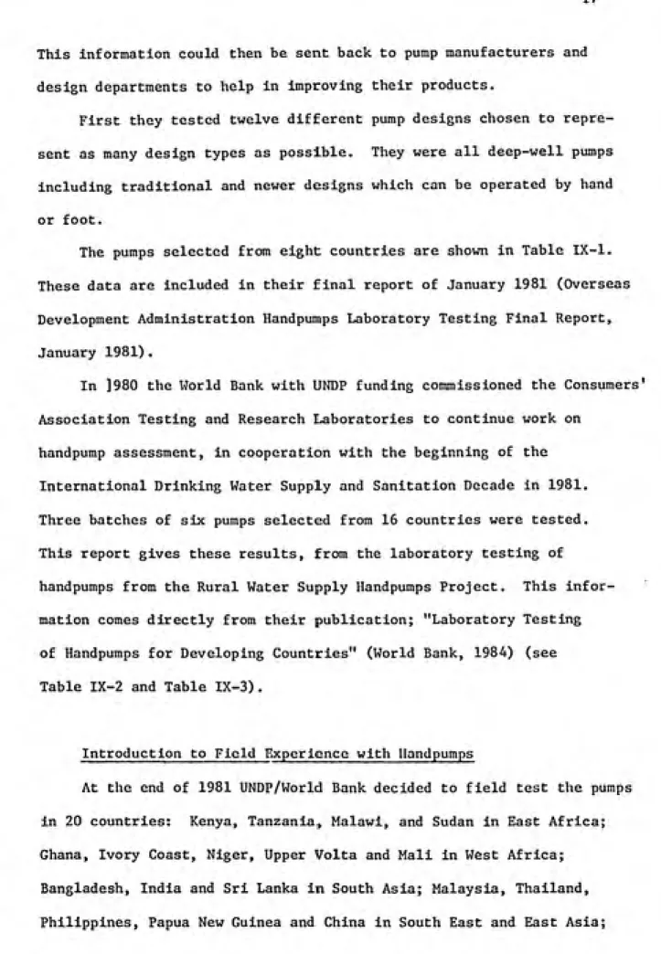
Korat l^l^>
Korat Pump Description
The Korat 608 A-1 is a deep-well force pump, made In
ͣ
Thailand. The pumpstand Is mainly cast Iron with a rack
and quadrant mechanism and a wooden handle. It must be
mounted on a plinth at least as tall as the largest
container to be used. The cylinder is seamless brass |
tube, and the plunger has two conventional leather cup i
seals. There are two foot valves, one in the base of •
the cylinder, the other at the end of a short dip tube j
below. >
Materials of Construction
COMPONENT MATERIAL(S)
Pumpstand body Quadrant and rack
Handle Handle bearings Cylinder Plunger Cup seals Foot valve Drop pipe Pump rod s
Cast iron
Cast Iron
Wood
Proprietary ball races
Extruded brass
Cast gunmetal and bronze
Leather
Cast gunmetal and leather
Galvanised steel Mild steel -WEIGHTS--fr-MEASORES-Weights Dimensions Pumpstand Cylinder assembly Pump rods A7 kg 5.5 kg
1.I kg per metre Nominal cylinder bore: 76 mm Actual pump stroke: 80 mm Nominal volume per stroke: 363 ml
Drop pipe size: 1.50 Inches
Outside diameter of
below-ground assembly: 90 mm Pump rod diameter: 0.5 inches Maximum usable cylinder
length: 255 mm Manufacturing Techniques
The manufacturing techniques required to make the pump are listed
below:-Above-ground Assembly
Iron foundry
Brass & gunmetal foundry
Basic machining
Wood work
The pumpstand is principally constructed of 8 Iron castings. All involve
relatively simple patterns and moulding skills. Machining is mainly straight¬
forward lathe and drilling work. The doslgnu of the romponi-MUH .irtr suitable for
basic tooling and hence inexpensive but effective quality control.
Below-ground Brass & gunmetal foundry
Assembly Leather cutting and forming
Basic machining
significant wear. The leather cup seals and valves showed signs of wear, but still worked satisfactorily.
Breakdown Incidence
Breakdowns are shown in bold type.
Hours: 1072 2044 3060
3595 4029
Inspection and full performance test Inspection and volume flow I I Inspection and volume flow
Quadrant Handle and Rack Quadrant
Seized and Rack
Worn Out Inspection and volume flow Inspection and full performance test FINAL INSPECTION
Pumpstand (a) Quadrant teeth almost entirely worn away - rack
teeth also worn but could be upended and used for a
while with a new quadrant
(b) Both guide rollers behind rack seized on their
shafts
(c) Upper guide rod had "picked up" on Its bush
Cylinder Slight scratching of cylinder bore but no significant wear
Plunger (a) Plunger valve noticeably worn on Its diameter but
still working
(b) Some scratches on both cup leathers, and one distorted, but still serviceable
(c) Small amounts of sand lodged behind both cup leathers Foot Valves (a) Leather sealing washer in cylinder foot valve has
compressed, allowing metal-to-mctal contact between
valve and seat
(b) Split rubber seal in dip tube foot valve
Corrosion Noticeable corrosion of all ferrous parts, particularly lock nut between connecting rod and plunger, and dip tube
valve body.
Estimated total amount of water pumped in 4000 hours... 3.5 million litres.
: VERDICT
A robust pump potentially suitable for community water supply. The rack and quadrant will wear In time but they, can be easily replaced. It might be
better to consider an India Mk II approach eliminating the rack and
simplifying the quadrant. Easy to maintain or repair above-ground, difficult
below-ground, though cylinder assembly robust and reliable. Potentially dangerous moving parts should be permanently shrouded. Moderately priced.
^
EXPERIENCE WITH KORAT PUMP
The Korat pump was developed for use throughout rural Thailand. The
pump body and the cylinder are made of 2-inch seamless pipe. Steel
balls are used in the check valves. Local hardwood and leather are used
for the handle and piston cups. The pump is suitable for rural water
FIGURE II. 4 Korat Hand Pump
®
«r
®
PUMP MADE IN KORAT (THAILAND) OF PIPE COMPONENTS
(SOURCE: McJunkin, F.E. 1977 p. 187)1
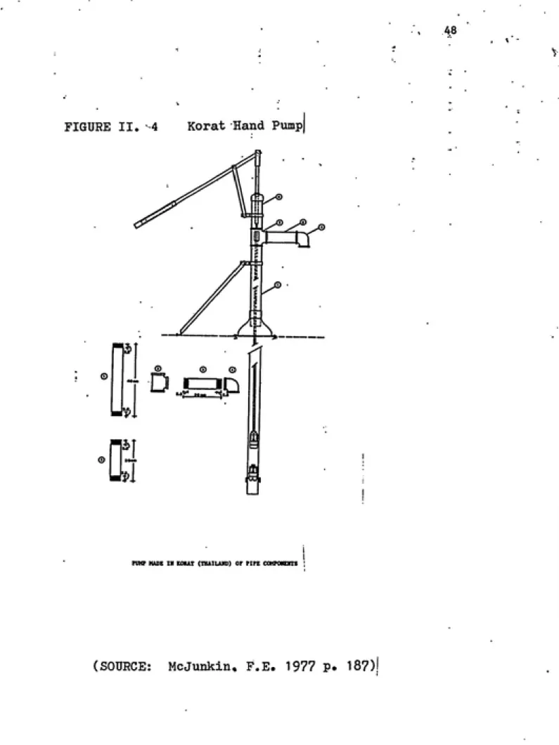
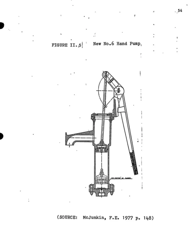
New No.6 -Pump Description
The New No. 6 Is a shallow-well suction pump, made
in Bangladesh' and constructed almost entirely of
cast iron. It Is mounted directly onto a 1.5 inch rising main. The plunger uses a moulded PVC cup washer. The check valve is a simple leather flap, weighted with cast Iron.
It appears crude and rather rough at first sight,
but is commendably simple and robust.
Materials of Construction
COMPONENT MATERIAL(S) Pumpstand body Handle Bearings Plunger Cup seal Base valve
G-JSt Iron ',
Cast iron
Mild steel pivot shafts bear on holes drilled In iron cislings
C:ist Iron Moulded I'VC Lea t he r
WEIGHTS and MEASURES
Weights
Dimensions
Pumpstand 31.0 kg
Nominal cylinder bore: 90 mm Actual pump stroke: 219 mm Nominal volume per stroke: 1393 ml Drop pipe size: 1.5 Inches
r No. 6 Pump
Manufacturing Techniques
The manufacturing techniques required to make the pump are listed below:-Iron Foundry Plastic moulding
Simple machining Leather crafting
The New No.6 Is well-suited fiar manufacture In developing countries where
adequate skills In iron foundry work and basic machining are available. The
pump has been designed Intelligently to avoid close tolerances In casting or
machining.
Ease of Installation, Maintenance and Repair
Ease of Installation
The drop pipe must be securely Installed to support tlie pumpstand, otherwise this suction pump Is easy to install. Only basic tools and skills are required.
Ease of Maintenance ;ind Repair
This pump is likely to require frequent Jittention to the plunger and check
valve, but Is very simple. Most jobs can be don<i with flat spanners and
pliers. A pipe wr«nch may be needed to disra.inllo thir plunger, which may
become heavily corroded.
PUMP PERFORMANCE
Volume Flow, Work Input and Efficiency
The description of the method can be found in the Test Procedure.
HEAD 7 m
Nominal pumping
rate (strokes/min) 20 30 W
Vol/stroke (litres) 1.30 1.20 1.29 Work input/stroke (J) 148 121 134
Efficiency (X) 59 67 65
ENDURANCE
A detailed description of the endurance test method can be found in the Test
Procedure. General Comments
The pump was tested at 30 strokes per minute at 7 metres head.
The original cup washer and plunger valve were badly worn after 1000 hours,
and were replaced. The cup washer failure was probably due to the initial
roughness of the bore. The replacements lasted the remaining 3000 hours of
the test programme, though both were badly worn at the end. The check valve •
was also replaced at 1000 hours, and the replacement also lasted out the
remainder of the 4000 hours.
The final inspection revealed wear in the handle pivot shafts and the
associated holes in the handle, pump top and connecting rod eye. The pump was
still working however, and would probably continue for some time.
Corrosion was extensive. The cast iron pumpstand has no protective coating'and
was rusting wherever it had got wet. Because of rust the plunger was Impossible
to dismantle and the retaining screw could not be removed from the check valve
weight.
The cylinder was in good condition at the end of the test. The original
machining marks in the bore were still clearly visible although the high spots
had been removed.