Spectrum™ Technology Platform
Version 9.0
Contents
Chapter 1: Introduction...7
Enterprise Data Management Architecture...8
The Star Schema Data Warehouse Design...10
Advantages of a Star Schema...13
Chapter 2: Connecting to Data Sources and Data Warehouses...15
Introduction to Resources...16
Databases...16
Adding or Modifying a Database Connection...16
Deleting a Database Connection...16
JDBC Drivers...17
Supported Database Data Types...18
File Servers...19
Connecting to an FTP File Server...19
Connecting to a Hadoop Distributed File System...19
Modifying a File Server...21
Deleting a File Server...21
External Web Services...21
Adding a SOAP Web Service...22
Adding a REST Web Service...24
Renaming an External Web Service...25
Deleting an External Web Service...25
Using a Windows Mapped Drive...26
Chapter 3: Populating the Data Warehouse...29
Preparing Your Data...30
Populating a Time Dimension Table...31
Populating a Dimension Table...32
Populating a Fact Table...33
Adding a Time Stamp to Records in a Data Warehouse...37
Chapter 4: Updating the Data Warehouse...39
Defining a Data Warehouse Update Schedule...40
Using a Global Cache for Queries...44
Deleting a Cache...45
Using a Local Cache for Queries...46
Chapter 5: Stages Reference...47
Call Stored Procedure...48
Field Selector...50
Generate Time Dimension...50
Options...51
Output...53
Query Cache...54
Query DB...56
Read From DB...58
Visual Query Builder...58
Read From File...61
Defining Fields In a Delimited Input File...65
Defining Fields In a Line Sequential or Fixed Width File...66
Sorting Input Records...68
The File Definition Settings File...69
Read from HL7 File...72
Flattening HL7 Data...76
Adding a Custom HL7 Message...79
Read from Variable Format File...80
Defining Fields in Delimited Variable Format Files...85
Defining Fields in a Line Sequential or Fixed Width Variable Format
File...87
Flattening Variable Format Data...89
Read From XML...89
Flattening Complex XML Elements...93
SQL Command...94
Transposer...97
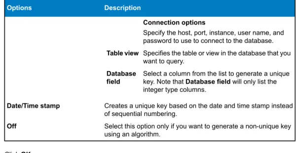
Unique ID Generator...98
Defining a Unique ID...99
Using Algorithms to Augment a Unique ID...100
Defining a Non-Unique ID...101
Write to Cache...103
Write to DB...104
Configuring Error Handling in Write to DB...107
Write to File...107
Defining Fields In a Delimited Output File...111
Defining Fields In a Line Sequential or Fixed Width File...113
Sorting Output Records...115
The File Definition Settings File...115
Write to Variable Format File...118
Tag Names in Variable Format Files...124
Write to XML...125
Using Namespaces in an XML Output File...128
Creating Complex XML from Flat Data...129
Date and Number Patterns...131
Date and Time Patterns...131
Number Patterns...133
5 Enterprise Data Integration Guide
1
Introduction
In this section:
•
Enterprise Data Management Architecture . . . .8
Enterprise Data Management Architecture
With Spectrum™Technology Platform, you can build a comprehensive enterprise data management
process, or you can target those individual areas in which your company needs improvement. The following diagram illustrates a complete solution that takes data from its source, through data enrichment and data quality processes, feeding a master data management hub which makes a single view of the data available to multiple business applications.
Data Discovery
Data discovery is the process of scanning your data resources to get a complete inventory of your data landscape. Spectrum™Technology Platform can scan structured data, unstructured data, and
semi-structured data using a wide array of data profiling techniques. The results of the scan are used to automatically generate a library of documentation describing your company's data assets and to create a metadata repository. This documentation and accompanying metadata repository provide the insight Enterprise Data Management Architecture
you need before beginning data integration, data quality, data governance, or master data management projects.
For more information on the Spectrum™Technology Platform Data Discovery Module, contact your
account executive. Data Integration
Once you have an inventory of your data landscape, you need to consider how you will access the data you need to manage. Spectrum™Technology Platform can connect to data in multiple sources either
directly or through integration with your existing data access technologies. It supports batch and real time data integration capabilities for a variety of business needs including data warehousing, data quality, systems integration, and migration. Spectrum™Technology Platform can access data in RDBMS
databases, data warehouses, XML files, flat files, and variable format files. Spectrum™Technology
Platform supports SQL queries with complex joins and aggregations and provides a visual query development tool. In addition, Spectrum™Technology Platform can access data over REST and SOAP
web services.
Spectrum™Technology Platform can trigger batch processing based on the appearance of one or more
source files in a specified folder. This "hot folder" trigger is useful for monitoring FTP uploads and processing them as they occur.
Some of these data integration capabilities require a license for the Enterprise Data Integration Module. For more information, contact your account executive.
Finally, Spectrum™Technology Platform can integrate with packaged applications such as SAP and
Siebel.
Data Quality/Governance
Data quality and data governance processes check your data for duplicate records, inconsistent information, and inaccurate information.
Duplicate matching identifies potential duplicate records or relationships between records, whether the data is name and address in nature or any other type of customer information. Spectrum™Technology
Platform allows you to specify a consistent set of business match rules using boolean matching methods, scoring methods, thresholds, algorithms and weights to determine if a group of records contains duplicates. Spectrum™Technology Platform supports extensive customization so you can tailor the rules to the
unique needs of your business.
Once duplicate records have been identified, you may wish to consolidate records. Spectrum™Technology
Platform allows you to specify how to link or merge duplicate records so you can create the most accurate and complete record from any collection of customer information. For example, a single best-of-breed record can be built from all of the records in a household. The Advanced Matching Module is used to identify duplicates and eliminate them.
Data quality processes also standardize your data. Standardization is a critical process because standardized data elements are necessary to achieve the highest possible results for matching and identifying relationships between records. While several modules perform standardization of one type or another, the Spectrum™Technology Platform Data Normalization module provides the most
comprehensive set of standardization features. In addition, the Universal Name module provides specific data quality features for handling personal name and business name data.
Standardized data is not necessarily accurate data. Spectrum™Technology Platform can compare your
data to known, up-to-date reference data for correctness. The sources used for this process may include regulatory bodies such as the U.S. Postal Service, third-party data providers such as Experian or D&B, or your company's internal reference sources, such as accounting data. Spectrum™Technology Platform
is particularly strong in address data validation. It can validate or standardize addresses in 250 countries and territories around the world. There are two modules that perform address validation: the Address Now Module and the Universal Addressing Module.
To determine which one is right for you, discuss your needs with your account executive.
9 Enterprise Data Integration Guide
While Spectrum™Technology Platform can automatically handle a wide range of data quality issues,
there are some situations where a manual review by a data steward is appropriate. To support this, the Business Steward Module provides a way to specify the rules that will trigger a manual review, and it provides a web-based tool for reviewing exception records. It includes integrated access to third-party tools such as Bing maps and Experian data to aid data stewards in the review and resolution process. Data Enrichment
Data enrichment processes augment your data with additional information. Enrichment can be based on spatial data, marketing data, or data from other sources that you wish to use to add additional detail to your data. For example, if you have a database of customer addresses, you could geocode the address to determine the latitude/longitude coordinates of the address and store those coordinates as part of the record. Your customer data could then be used to perform a variety of spatial calculations, such as finding the bank branch nearest the customer. Spectrum™Technology Platform allows you to enrich
your data with a variety of information, including geocoding (with the Enterprise Geocoding Module), tax jurisdiction assignment (with the Enterprise Tax Module), geospatial calculations (with the Location Intelligence Module), and driving and walking directions between points (with the Enterprise Routing Module).
Master Data Management Hub
The Master Data Management (MDM) hub allows for rapid modeling of entities and their complex relationships across roles, processes and interactions. It provides built-in social network analysis capabilities to help you understand influencers, predict churn, detect non-obvious relationships and fraudulent patterns, and provide recommendations.
Spectrum™Technology Platform supports two approaches to the MDM hub. In the master hub approach,
the data is maintained in a single MDM database and applications access the data from the MDM database. In the registry approach, the data is maintained in each business application and the MDM hub registry contains keys which are used to find related records. For example, a customer's record may exist in an order entry database and a customer support database. The MDM registry would contain a single key which could be used to access the customer data in both places.
The Data Hub Module provides MDM capabilities.
The Star Schema Data Warehouse Design
Spectrum™Technology Platform supports the creation and maintenance of data warehouses that use
a star schema design. In a star schema, data is stored as either facts, which are specific descriptions of an event, or dimensional attributes, which are descriptions of the facts in the fact table. Facts change regularly and dimensions change slowly or never.
The following illustration shows the design of a star schema: The Star Schema Data Warehouse Design
This illustration shows the main characteristics of a star schema: a fact table, dimension tables, and joins.
Fact Table
Fact tables are the central tables in the star schema of your data warehouse. Fact tables usually contain numeric or quantitative information (called measures) that describe a specific event. For example, if you have a data warehouse that you use to generate a report on company revenue, you would have dollar_sales, and dollar_cost as columns within your fact table, as shown in the illustration above. Typically, facts are continuously valued and additive. "Continuously valued" means that the fact is a numeric measurement that has a value every time it is measured. "Additive" means that the fact can be summarized through addition.
Fact tables also contain a set of columns that form a concatenated, or composite key. Each column of the concatenated key is a foreign key drawn from a dimension table's primary key. For example, in the above illustration the fact table contains a column product_key which associates the fact with a specific product in the product_dimension table.
The level of detail in a fact table is called the grain. Every row in the fact table must be recorded to the same level of detail. In the diagram above, the measurements in the fact table are daily totals of sales
11 Enterprise Data Integration Guide
in dollars, sales in units, and cost in dollars of each product sold. The grain is daily. Each record in the fact table represents the total sales of a specific product in a retail store on one day. Each new combination of product, store, or day generates a different record in the fact table.
Fact tables are populated with data extracted from a data source. The data source can be an OLTP system or a data warehouse. Spectrum™Technology Platform takes a snapshot of the source data on
a regular schedule and moves the data to the data warehouse, usually at the same time every day, week or month.
A star schema can have multiple fact tables. Use a schema with multiple fact tables to separate sets of measurements that share a common subset of dimension tables, or to track measurements with different grains.
Dimension Table
Dimension tables store data that describe the information in the fact table. For example, if sales_total differed one month from the next you would look to the dimensions to tell you why. The same dimension table can be used with different fact tables.
Dimension tables have attributes and a single part primary key that joins the dimension table to the fact table. Attributes are the columns in the dimension table. The single part primary key allows you to quickly browse a single dimension table. Browsing a dimension table can help determine the best way to query the fact table.
Time dimension tables are necessary for accurate time-based calculations because you sometimes cannot easily extract the necessary date data from the records. For example, the following records are in a sales database. Note that there are time gaps between records. For example, there is no record for the day 1/4/2012. Amount Product Date $10.00 Red Shirt 1/3/2012 $5.00 Red Shirt 1/5/2012 $15.00 Red Shirt 1/7/2012
If you query these records and calculate the average sales per day, the answer would be $10.00 ($30 / 3 records). However, this is incorrect because the three records actually span a period of five days. If you have a time dimension table with a record for each day, you could join that table with the above table to get this:
Amount Product Date $10.00 Red Shirt 1/3/2012 1/4/2012 $5.00 Red Shirt 1/5/2012 1/6/2012 $15.00 Red Shirt 1/7/2012
Calculating the average sales per day using these records, you would get the correct answer: $6.00 ($30 / 5 days).
In addition, you could account for arbitrary time attributes such as holidays, weekends, and quarters in your calculation. For example, if 1/6/2012 happened to be a holiday and you were only interested in average sales per workday then the answer would be $7.50.
Joins
Joins define relationships between a fact table and dimension tables in the star schema. The primary key in the dimension table is the foreign key in the fact table. The fact table must contain a primary key value from each dimension table. The reference from the foreign key to the primary key is the mechanism for verifying values between the two tables. Join relationships of this type ensure the referential integrity of a data warehouse. Referential integrity must be maintained to ensure valid query results.
Each record in a dimension table can describe many records in the fact table, making the join cardinality of dimension tables to fact tables one-to-many.
In the illustration above, product_key is the primary key in the product_dimension table and the foreign key in the sales_fact table. This join represents the relationship between the company’s products and its sales.
Advantages of a Star Schema
A well-designed schema allows you to quickly understand, navigate and analyze large multidimensional data sets. The main advantages of star schemas in a decision support environment are:
Query Performance
Queries run faster against a star schema database than an OLTP system because the star schema has fewer tables and clear join paths. In a star schema design, dimensions are linked through the central fact table. Dimensions are linked with each other through one join path intersecting the fact table. This design feature enforces accurate and consistent query results.
Load Performance and Administration
The star schema structure reduces the time required to load large batches of data into a database. By defining facts and dimensions and separating them into different tables, the impact of a load operation is reduced. Dimension tables can be populated once and occasionally refreshed. New facts can be added regularly and selectively by appending records to a fact table.
Built-in Referential Integrity
A star schema is designed to enforce referential integrity of loaded data. Referential integrity is enforced by the use of primary and foreign keys. Primary keys in dimension tables become foreign keys in fact tables to link each record across dimension and fact tables.
Efficient Navigation Through Data
Navigating through data is efficient because dimensions are joined through fact tables. These joins are significant because they represent fundamental relationships of real business processes. You can browse a single dimension table in order to select attribute values to construct an efficient query.
13 Enterprise Data Integration Guide
2
Connecting to Data Sources
and Data Warehouses
In this section:
•
Introduction to Resources . . . .16
•
Databases . . . .16
•
File Servers . . . .19
•
External Web Services . . . .21
Introduction to Resources
In Spectrum™Technology Platform, a resource is a connection to a data source that you want to use
as input to, or output from, a dataflow. There are three kinds of resources: • Databases
• File servers • Web services
If you want to access data in an external resource you must first define a connection to the resource using Management Console. For example, if you want to read data from an XML file into a dataflow, and the XML file is located on a remote file server, you would have to define a connection to the file server before you can define the input XML file in a dataflow. Similarly, if you want to write dataflow output to a database, you must first define the database as an external resource.
If you want to read from or write to data located in a file on the Spectrum™Technology Platform
server itself there is no need to define a connection. Note:
Databases
Adding or Modifying a Database Connection
A database connection enables Spectrum™Technology Platform to read and write data to a database.
You must define a database connection in order to create dataflows that read data from the database or write data to the database.
1. Open the Management Console.
2. ExpandResourcesthen clickConnections.
3. ClickAddorModify. TheConnection Propertiesdialog box will appear.
4. Enter a name for the connection in theConnection namefield. This can be anything you choose. 5. Select the appropriate database type in theDatabase driverfield.
Spectrum™Technology Platform comes with SQL Server and Oracle connection types. If you want
to connect to a different database type, you must define a JDBC driver before configuring the database connection.
6. Complete the fields in theConnection Optionstable. This includes the host, port, instance, user name, and password.
7. Test the connection by clickingTest. 8. ClickOK.
Related Links
Read From DBon page 58
Write to DBon page 104
Query DBon page 56
Deleting a Database Connection
1. Open the Management Console.2. ExpandResourcesthen clickConnections.
3. Highlight the connection you want to update and clickDelete. You will receive a confirmation message asking if you wish to delete the connection.
4. ClickOKto confirm.
JDBC Drivers
Adding or Modifying a JDBC Driver
Spectrum™Technology Platform can read data from, and write data to, any database using a JDBC
driver. To access data using a JDBC driver you must first define the driver, then create a database connection that uses the driver. The following procedure describes how to create or modify a JDBC driver.
JDBC driver settings are very specific and require total accuracy to function. Ensure you have the correct information from your database/database driver provider before adding a JDBC driver. Note:
1. Open the Management Console.
2. ExpandResourcesthen clickJDBC Drivers.
3. ClickAddto create a new JDBC driver connection. If you want to modify an existing drvier, select the driver you want to modify then clickModify.
Spectrum™Technology Platform comes with three predefined JDBC drivers: Internal (which
is used by the system), SQL Server, and Oracle. You cannot modify or delete these. Note:
4. In theJDBC driver configuration namefield, enter a name for the driver. The name can be anything you choose.
5. In theJDBC driver class namefield, enter the Java class name of the driver. You can typically find the class name in your JDBC driver's documentation.
For example, to use the Microsoft JDBC driver with an SSL connection to a SQL database, you might enter the following:
com.microsoft.sqlserver.jdbc.SQLServerDriver
6. In theConnection string templatefield, enter the template to use for the connection string. For example, to enable an SSL connection to a SQL database, you would enter the following: jdbc:sqlserver://${host}:${port};databaseName=${instance};encrypt=true;TrustServerCertificate=true 7. In theDriver filessection, clickAdd.
8. Navigate to and select the appropriate driver and clickSave.
9. In theConnection Propertiessection, clickAdd. TheJDBC Connection Propertydialog box will appear.
10.In theLabelfield, enter the property's label. The label can be any name you choose. For example, username.
11.In theProperty tokenfield, enter the token to use in the URL. For example,user.
You will need to enter bothuserandpasswordproperty tokens for every JDBC connection you create.
Note:
12.ClickOK. Related Links
Read From DBon page 58
Write to DBon page 104
Query DBon page 56
Deleting a JDBC Driver
1. Open the Management Console.
2. ExpandResourcesthen clickJDBC Drivers.
3. Select an existing JDBC driver and clickDelete. TheConfirm Deletedialog box will appear.
17 Enterprise Data Integration Guide
If any connections are using this driver, you will be notified which connections are using it and you cannot delete the driver.
Note:
Supported Database Data Types
Spectrum™Technology Platform supports the following data types commonly used in databases:
A numeric data type that supports 38 decimal points of precision. Use this data type for data that will be used in mathematical calculations requiring a high degree of bigdecimal
precision, especially those involving financial or geospatial data. The bigdecimal data type supports more precise calculations than the double data type.
A logical type with two values: true and false. boolean
A data type that contains a month, day, and year. For example, 2012-01-30 or January 30, 2012. You can specify a default date format in Management Console.
date
A data type that contain a month, day, year, and hours, minutes, and seconds. For example, 2012/01/30 6:15 PM.
datetime
A numeric data type that contains both negative and positive double precision numbers between 2-1074and (2-2-52)×21023. In E notation, the range of values is 4.9E-324 to double
1.7976931348623157E308. For information on E notation, see
en.wikipedia.org/wiki/Scientific_notation#E_notation.
A numeric data type that contains both negative and positive single precision numbers between 2-149and (2-223)×2127. In E notation, the range of values is 1.4E-45 to float
3.4028235E38. For information on E notation, see
en.wikipedia.org/wiki/Scientific_notation#E_notation.
A numeric data type that contains both negative and positive whole numbers between -231(-2,147,483,648) and 231-1 (2,147,483,647).
integer
A numeric data type that contains both negative and positive whole numbers between -263(-9,223,372,036,854,775,808) and 263-1 (9,223,372,036,854,775,807). long
A sequence of characters. string
A data type that contains the time of day. For example, 21:15:59 or 9:15:59 PM. time
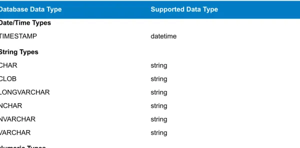
Other database data types are automatically mapped to one of the supported data types as follows: Table 1: Mapping of Database Data Types to Supported Data Types
Supported Data Type Database Data Type
Date/Time Types datetime TIMESTAMP String Types string CHAR string CLOB string LONGVARCHAR string NCHAR string NVARCHAR string VARCHAR Numeric Types Databases
Supported Data Type Database Data Type
long BIGINT double DECIMAL double FLOAT bigdecimal NUMERIC float REAL integer SMALLINT integer TINYINT Boolean Types boolean BIT
File Servers
Connecting to an FTP File Server
If you need to read data from, or write data to, files on an FTP server you must define a connection to the file server using Management Console. Once you do this, you can create dataflows in Enterprise Designer that can read data from, and write data to, files on the file server.
1. Open the Management Console.
2. ExpandResourcesthen clickFile Servers. 3. ClickAdd.
4. In theConnection namefield, enter a name for the new connection . The name can be anything you choose.
5. In theHostfield, enter the name or IP address of the FTP server. 6. In thePortfield, enter the network port number.
7. In theTypefield, choose FTP.
8. In theUser namefield, enter the user name to use when authenticating to the FTP server. This is required only if the FTP server requires it.
9. In thePasswordfield, enter the password to use when authenticating to the FTP server. This is required only if the FTP server requires it.
10.ClickOK.
11.If you wish to test the server, highlight the connection you want to test and click theTestbutton on theFile Serversdialog box.
After you have defined a connection to a file server, it becomes available in source and sink stages in Enterprise Designer, such as Read from File, Write to File, and so on. You can select the FTP server when you clickRemote Machinewhen defining a file in a source or sink stage.
Connecting to a Hadoop Distributed File System
Hadoop Distributed File System (HDFS) is an open source distributed file system. It provides high-performance access to large data sets and can be run on inexpensive hardware. If you have an HDFS system you can configure Spectrum™Technology Platform to read data from, or write data to,
files on your HDFS cluster by defining a connection to the HDFS cluster using Management Console. Once you do this, you can create dataflows in Enterprise Designer that can access files on HDFS.
19 Enterprise Data Integration Guide
For more information on HDFS, see the documentation available on the Apache Hadoop project website:hadoop.apache.org.
Note:
1. Open the Management Console.
2. ExpandResourcesthen clickFile Servers. 3. ClickAdd.
4. In theConnection namefield, enter a name for the new connection . The name can be anything you choose.
5. In theHostfield, enter the name or IP address of the NameNode in the HDFS cluster. 6. In thePortfield, enter the network port number.
7. In theTypefield, choose HDFS. 8. UnderUser, select one of the following:
Choose this option if authentication is enabled in your HDFS cluster. This option will use the user credentials that the server runs under to
authenticate to HDFS. Server user
Choose this option if authentication is disabled in your HDFS cluster. User name
9. In theProtocolfield select one of the following:
Select this option if the HDFS cluster is running HDFS 1.0 or later. This protocol supports both read and write operations.
WEBHDFS
Select this option if the HDFS cluster is running a version older than HDFS 1.0, or if your organization does not allow the WEBHDFS protocol. This protocol only supports the read operation.
HFTP
Select this option to access Hadoop archive files. If you choose this option, specify the path to the archive file in thePathfield. This protocol only supports the read operation.
HAR
10.If you selected the WEBHDFS protocol you can specify the following advanced options.
Specifies how many data nodes to replicate each block to. For example, the default setting of 3 replicates each block to three different nodes in the cluster. The maximum replication factor is 1024.
Replication factor
Specifies the size of each block. HDFS breaks up a file into blocks of the size you specify here. For example, if you specify the default 64 MB, each file is broken up Block size
into 64 MB blocks. Each block is then replicated to the number of nodes in the cluster specified in theReplication factorfield.
Specifies the level of access to files written to the HDFS cluster by Spectrum™
Technology Platform. You can specify read and write permissions for each of the following:
File
permissions
The Execute permission is not applicable to Spectrum™Technology
Platform. Note:
This is the user specified above, eitherServer useror the user specified in theUser namefield.
User
This refers to any group of which the user is a member. For example, if the user is john123, then Group permissions apply to any group of which john123 is a member.
Group
This refers to any other users as well as groups of which the specified user is not a member.
Other
11.ClickOK.
12.If you wish to test the server, highlight the connection you want to test and click theTestbutton on theFile Serversdialog box.
After you have defined a connection to an HDFS cluster, it becomes available in source and sink stages in Enterprise Designer, such as Read from File, Write to File, and so on. You can select the HDFS cluster when you clickRemote Machinewhen defining a file in a source or sink stage.
Modifying a File Server
1. Open the Management Console.
2. ExpandResourcesthen clickFile Servers.
3. Highlight the server you want to update and clickModify. 4. Make the appropriate changes to the server and clickOK.
Modifying a configuration may cause any dataflows reference that configuration to no longer function properly.
Note:
Deleting a File Server
1. Open the Management Console.
2. ExpandResourcesthen clickFile Servers.
3. Highlight the file server you want to delete and clickDelete. You will receive a confirmation message asking if you wish to delete the server.
4. ClickOKto confirm.
Deleting a file server will cause any dataflows referencing that file server to no longer function properly.
Note:
External Web Services
External web services are data processing services provided over the Internet by a third party. You can define external web services in the Management Console and then use them as a stage in a dataflow, or as a service exposed on your Spectrum™Technology Platform server. This allows you to incorporate
almost any kind of processing into your Spectrum™Technology Platform environment, since there are
a wide variety of web services available on the Internet.
External web services show up in the palette in Enterprise Designer and you can work with them as you do other stages. The following shows an example of two external web services,
CompanyReviewsWebService and TimeZoneLookupWebService.
21 Enterprise Data Integration Guide
Spectrum™Technology Platform supports external web services that use REST, SOAP 1.1, or SOAP
1.2 messaging.
Adding a SOAP Web Service
This topic describes how to define a connection to an external third-party web service using the SOAP protocol.
1. Open the Management Console.
2. Expand theResourcesnode, then clickExternal Web Services. 3. ClickAdd.
4. In theNamefield, enter the name you want to give the external web service. This will be the stage name shown in Enterprise Designer and the service name on the Spectrum™Technology Platform
server. The name can be anything you want but must not already be used by another web service on your system.
5. UnderExternal service type, selectSOAP.
6. In theTimeoutfield, enter the number of seconds that are allowed to elapse before a request submitted to the web service times out.
The timeout value you specify here applies to any request made to the web service. This includes not only transactions made against the exposed web service, but also requests Note:
made in the course of configuring the web service. Such configuration requests are invoked by clickingRefresh, choosing a new item in theOperationlist, and running preview. Timeouts can occur when performing any of these actions. If timeouts do occur, increasing theTimeout value can help to avoid them, provided the web service is actually up and running.
7. If you want to make the web service available to use in dataflows and to access as a Spectrum™
Technology Platform service:
a) Check theExpose as servicebox.
b) If you want the web service exposed as a SOAP web service, check theSOAPbox. The web service will then be listed at http://<ServerName>:<Port>/soap.
c) If you want the web service exposed as a REST web service, check theRESTbox. The web service will then be listed at http://<ServerName>:<Port>/rest.
8. In theURLfield, enter the URL of the web service's WSDL.
9. Enter a user name and password if they are required to access the external web service. External Web Services
10.ClickRefreshto populate theOperationlist with the operations that are available from the web service.
Some web services require you to provide a user name and password before you can access them. In this case you must provide the required credentials prior to clickingRefresh. Otherwise, the refresh operation will fail.
Note:
11.In theOperationlist, select the web service operation you want to perform.
When you select a web service operation in theOperationlist, the field names for the operation request and response are listed on theRequestandResponsetabs.
12.Check theUse WS-Securitybox to apply security to your web service by sending credentials through the header of the SOAP message.
13.If the web service supports request headers, configure theRequest Headertab as follows. If it does not, go to step14on page 23.
a) Select the header parameters you want to include in the request by checking or clearing the boxes. If a check box is checked and grayed out, it means that the parameter is required and you cannot disable it.
b) In theValuecolumn, specify the value you want to use for each parameter.
14.On theRequesttab (orRequest Bodytab if the web service supports request headers), specify the settings and values you want for the request fields.
a) To use a subset of the available request fields, select an XPath location in theFilterfield. All XPath location paths that match the selected path, and any descendant paths, are displayed in the table and will be included in the request.
b) In theField Namecolumn, enter the field name you want to reference each request field. This is the name that will be used for input field name for the resulting Spectrum™Technology Platform
service, if the field is exposed.
Each XPath location in the table is associated with a corresponding request field. The request field is given an initial default name provided by the external web service. For each request field, you can either accept the default name or enter a new name.
c) In theDefault Valuecolumn, specify a default value for each request field, if desired.
d) Select theExposeoption for each request field you want to expose as an available input field in the resulting Spectrum™Technology Platform service. If you want to expose all request fields,
select theExposeoption in the table heading row.
e) If you want to view a template of the XML that will be sent as a request to the external web service, clickView Template.
15.On theResponsetab, specify the settings and values you want for the response fields.
a) Select theReturn response XML as textoption if you want the external web service response to be returned as a single field namedSoapResponse. A template of the XML response is displayed. Proceed to step16on page 24.
If you do not select theReturn response XML as textoption, the web service response is returned as individual fields based on the specified mapping of field names to XPath location paths. Continue with the remaining steps below.
b) If you want to filter the list of fields displayed, select an XPath in theFilterfield.
All XPath location paths that match the selected path, and any descendant paths, are displayed in the table and will be included in the response.
c) In theField Namecolumn, change the default field name, if desired.
Each XPath location path in the table is associated with a corresponding response field that is given an initial default name provided by the external web service. For each response field, you can either accept the default name or enter a new name.
d) Select theExposeoption for each response field you want to expose as an available output field in the resulting Spectrum™Technology Platform service. If you want to expose all response fields,
select theExposeoption in the table heading row.
A field which has itsExposeoption selected will be returned in the response from the external web service. Each field is mapped to an XPath location provided by the external web service. If the fields that have theirExposeoption selected are mapped to XPath locations that are all at
23 Enterprise Data Integration Guide
the same level, then individual records will be returned for the fields. However, if the exposed fields are mapped to XPath locations at different levels, then a hierarchical data object will be returned.
e) If you want to view a template of the XML that will be sent as a response from the external web service, clickView Template.
16.On thePreviewtab, enter any test data you would like to submit to the external web service, then clickPreviewto see the web service's response.
17.ClickOKto save the external web service. Related Links
External Web Serviceson page 21
Adding a REST Web Service
This topic describes how to define a connection to an external third-party web service using the REST protocol.
1. Open the Management Console.
2. Expand theResourcesnode, then clickExternal Web Services. 3. ClickAdd.
4. In theNamefield, enter the name you want to give the external web service. This will be the stage name shown in Enterprise Designer and the service name on the Spectrum™Technology Platform
server. The name can be anything you want but must not already be used by another web service on your system.
5. UnderExternal service type, selectREST.
6. In theTimeoutfield, enter the number of seconds that are allowed to elapse before a request submitted to the web service times out.
The timeout value you specify here applies to any request made to the web service. This includes not only transactions made against the exposed web service, but also requests Note:
made in the course of configuring the web service. Such configuration requests are invoked by clickingRefresh, choosing a new item in theOperationlist, and running preview. Timeouts can occur when performing any of these actions. If timeouts do occur, increasing theTimeout value can help to avoid them, provided the web service is actually up and running.
7. If you want to make the web service available to use in dataflows and to access as a Spectrum™
Technology Platform service
a) Check theExpose as servicebox.
b) If you want the web service exposed as a SOAP web service, check theSOAPbox. The web service will then be listed at http://<ServerName>:<Port>/soap.
c) If you want the web service exposed as a REST web service, check theRESTbox. The web service will then be listed at http://<ServerName>:<Port>/rest.
8. In theURLfield, enter the URL of the web service.
You may include parameters in the URL if you want to pre-populate theRequestandResponse tabs with the parameters used by the web service. For example, let's say you are defining an external web service for a web service that provides reviews of businesses. You might enter a URL like this: http://ws.someprovider.com/business_reviews?term=insurance&location=207325 Based on this, the external web service you define would have two fields,termandlocation. If you omit parameters from the URL you can specify them later in this procedure.
9. Enter a user name and password if they are required to access the external web service. 10.ClickRefreshto populate theOperationlist with the operations that are available from the web
service.
Some web services require you to provide a user name and password before you can access them. In this case you must provide the required credentials prior to clickingRefresh. Otherwise, the refresh operation will fail.
Note:
11.In theOperationlist, select the web service operation you want to perform.
When you select a web service operation in theOperationlist, the field names for the operation request and response are listed on theRequestandResponsetabs.
12.On theRequesttab, specify the settings and values you want for the request fields.
a) The parameter list shows the parameters contained in the URL you previously entered. If you want to add additional parameters, clickAdd. If you want to delete a parameter, select it in the table and clickDelete.
b) In theField Namecolumn, enter the field name you want to reference each parameter. This is the name that will be used for input field name for the resulting Spectrum™Technology Platform
service, if the field is exposed.
c) Specify a default value for each request field, if desired.
d) Select theExposeoption for each request field you want to expose as an available input field in the resulting Spectrum™Technology Platform service. If you want to expose all request fields,
select theExposeoption in the table heading row.
e) If you want to view a template of the request URL that will be sent to the external web service, clickView Template.
13.On theResponsetab, specify the type response returned by the third-party web service.
Spectrum™Technology Platform will return a single field namedRestResponse
containing the REST response. This option works with all response types. Text
Select this option if the third-party web service returns delimited data such as CSV. Spectrum™Technology Platform will parse the data and return it as individual
fields. Delimited
Select this option if the third-party web service returns XML. Spectrum™Technology
Platform will parse the data and return it as individual fields. XML
Select this option if the third-party web service returns JSON. Spectrum™
Technology Platform will parse the data and return it as individual fields. JSON
14.On thePreviewtab, enter any test data you would like to submit to the external web service, then clickPreview.
15.ClickOKto save the external web service. Related Links
External Web Serviceson page 21
Renaming an External Web Service
Renaming an external web service will break existing jobs/services that reference the external web service. If no jobs/services reference the external web service, or if you want to change existing jobs/services to reference a different external web service or the new name, you can safely rename the external web service.
1. In Management Console, expand theResourcesnode, then clickExternal Web Services. 2. Highlight the external web service you want to rename and clickRename.
3. Confirm that you want to rename the external web service by clickingOK. 4. Enter a new name for the external web service, then clickOK.
Related Links
External Web Serviceson page 21
Deleting an External Web Service
Deleting an external web service will break existing jobs/services that reference the external web service. If no jobs/services reference the external web service, or if you want to change existing jobs/services to reference a different external web service, you can safely delete the external web service.
1. In Management Console, expand theResourcesnode, then clickExternal Web Services.
25 Enterprise Data Integration Guide
2. Highlight the external web service you want to delete and clickDelete. You will receive a confirmation message asking if you wish to delete the external web service.
3. ClickOKto confirm. Related Links
External Web Serviceson page 21
Using a Windows Mapped Drive
If you are running the Spectrum™Technology Platform server on a Windows server you can provide
Enterprise Designer and Management Console users with access to data stored on a mapped drive. For example, you may want to design dataflows that read data from, or write data to, files located on a drive mapped to the Windows server running Spectrum™Technology Platform. Since the Spectrum™
Technology Platform server runs as a Windows service under a particular user account (often the Local System account) you need to define the mapped drive in the server's start-up process in order for it to be visible in Enterprise Designer and Management Console.
1. Stop the Spectrum™Technology Platform server.
2. Under the folder where the Spectrum™Technology Platform server is installed, go to
server\bin\wrapper. For example,C:\Program Files\Pitney Bowes\Spectrum\server\bin.
3. Open the filewrapper.confin a text editor.
In the following steps you will add new properties to this file. It is important that you follow these instructions precisely and only add and modify the parameters described in the following steps. Do not modify any of the other parameters in this file.
Important:
4. Add the following lines:
wrapper.share.1.location wrapper.share.1.target wrapper.share.1.type wrapper.share.1.account wrapper.share.1.password
5. In thewrapper.share.1.locationproperty, specify the location of the mapped drive in UNC format.
Do not include a trailing backslash in the UNC. Note:
For example,
wrapper.share.1.location=\\myserver\share
6. In thewrapper.share.1.targetproperty, specify the drive letter to assign to this mapped drive. For example,
wrapper.share.1.target=Y: 7. In thetypeproperty, specifyDISK.
For example,
wrapper.share.1.type=DISK
8. If the share you are connecting to requires a user name and password, specify the user name in the wrapper.share.1.accountproperty and specify the password in the
wrapper.share.1.passwordproperty. Using a Windows Mapped Drive
For example,
wrapper.share.1.account=domain\user123 wrapper.share.1.password=mypassword1
If the Spectrum™Technology Platform server service is running under the Local System
user, you cannot specify a user name and password. If the share requires a user name and password you must modify the service to run under a different account.
Note:
Example of Mapped Drive Properties in Wrapper.conf
The following example shows two mapped drives being defined in thewrapper.conf file. wrapper.share.1.location=\\myserver\data wrapper.share.1.target=Y: wrapper.share.1.type=DISK wrapper.share.1.account=sample\user wrapper.share.1.password=samplepass wrapper.share.2.location=\\myserver\moredata wrapper.share.2.target=Z: wrapper.share.2.type=DISK wrapper.share.2.account=sample\user wrapper.share.2.password=samplepass 27 Enterprise Data Integration Guide
3
Populating the Data
Warehouse
In this section:
•
Preparing Your Data . . . .30
•
Populating a Time Dimension Table . . . .31
•
Populating a Dimension Table . . . .32
•
Populating a Fact Table . . . .33
Preparing Your Data
Before populating your data warehouse, you should ensure that your data is of good quality, and that it has all the attributes necessary to provide meaningful insights to business users. One common approach is to use an operational data store (ODS) for this purpose. An ODS is a database where you can perform data quality operations that prepare your data for loading into the data warehouse. Spectrum™Technology
Platform has a variety of features that can be implemented in an ODS to improve the quality of your data and also augment your data with spatial, demographic, or other data. If you currently do not have the following features licensed, contact Pitney Bowes Software for more information.
Parsing, Name Standardization, and Name Validation
To perform the most accurate standardization you may need to break up strings of data into multiple fields. Spectrum™Technology Platform provides advanced parsing features that enable you to parse
personal names, company names, and many other terms and abbreviations. In addition, you can create your own list of custom terms to use as the basis of scan/extract operations. The Universal Name Module provides this functionality.
Deduplication and Consolidation
Identifying unique entities enables you to consolidate records, eliminate duplicates and develop "best-of-breed" records. A "best-of-breed" record is a composite record that is built using data from other records. The Advanced Matching Module and Data Normalization Module provide this functionality. Address Validation
Address validation applies rules from the appropriate postal authority to put an address into a standard form and even validate that the address is a deliverable address. Address validation can help you qualify for postal discounts and can improve the deliverability of your mail. The Universal Addressing Module and the Address Now Module provide this functionality.
Geocoding
Geocoding is the process of taking an address and determining its geographic coordinates (latitude and longitude). Geocoding can be used for map generation, but that is only one application. The underlying location data can help drive business decisions. Reversing the process, you can enter a geocode (a point represented by a latitude and longitude coordinate) and receive address information about the geocode. The Enterprise Geocoding Module provides this functionality.
Location Intelligence
Location intelligence creates new information about your data by assessing, evaluating, analyzing and modeling geographic relationships. Using location intelligence processing you can verify locations and transform information into valuable business intelligence. The Location Intelligence Module provides this functionality.
Tax Jurisdiction Assignment
Tax jurisdiction assignment takes an address and determines the tax jurisdictions that apply to the address's location. Assigning the most accurate tax jurisdictions can reduce financial risk and regulatory liability.
Spectrum™Technology Platform software from Pitney Bowes Software integrates up-to-date jurisdictional
boundaries with the exact street addresses of your customer records, enabling you to append the correct state, county, township, municipal, and special tax district information to your records. Some example uses of tax jurisdiction assignment are:
• Sales and use tax Preparing Your Data
• Personal property tax • Insurance premium tax
The Enterprise Tax Module provides this functionality.
Populating a Time Dimension Table
A time dimension table is a table in a database that makes it possible to analyze historic data without using complex SQL calculations. For example, you can analyze your data by workdays versus holidays, weekdays versus weekends, by fiscal periods or by special events.
The following procedure describes how to use Spectrum™Technology Platform to populate a time
dimension table in your data warehouse.
Before beginning this procedure, you must have defined connections to the data warehouse in which you want to create a time dimension table. If you have not defined the necessary connection, seeIntroduction to Resourceson page 16.
Note:
1. In Enterprise Designer, selectFile>New>Dataflow>Job. 2. Drag the Generate Time Dimension stage onto the canvas.
3. Drag a Write to DB stage onto the canvas and connect the Generate Time Dimension stage to it. The dataflow should now look like this:
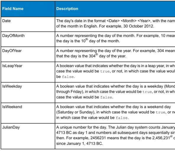
4. Double-click the Generate Time Dimension stage and configure it to produce the time dimensions you want. For more information, seeGenerate Time Dimensionon page 50.
The Julian day is usually used as a key value for a time dimension table if the grain is a day or more. If the grain is less than a day then you can generate a separate key by adding a Note:
Unique ID Generator stage to the dataflow. If you use the Julian day as the key, configure Generate Time Dimension to produce an integer column for Julian day values, and a column with the data type of date or datetime for date values.
5. Double-click the Write to DB stage on the canvas and configure it to point to the database and table where you want to create the time dimension table. For information on configuring Write to DB, see
Write to DBon page 104.
6. To preview the time dimension values before writing them to the time dimension table:
a) Right-click the channel connecting the Generate Time Dimension stage and the Write to DB stage, and selectAdd Inspection Point.
b) SelectRun>Inspect Current Flow.
The inspection pane appears at the bottom of the Enterprise Designer window and shows the data that will be written to the time dimension table. If necessary, you can make adjustments to the Generate Time Dimension stage and then re-run the inspection process to view the effect of your changes.
7. When you are satisfied with the dataflow, selectRun>Run Current Flowto execute the dataflow and populate the time dimension table.
31 Enterprise Data Integration Guide
Populating a Dimension Table
Dimension tables are part of a star schema and contain detailed information for the columns in the fact table. Dimension tables have attributes and a single part primary key that joins the dimension table to the fact table. The single part primary key allows you to quickly browse a single dimension table. Browsing a dimension table can help determine the best way to query the fact table.
The following procedure describes how to use Spectrum™Technology Platform to perform the initial
population of a dimension table in your data warehouse.
Before beginning this procedure, you must have defined connections to external resources you want to use as the source for the dimension table if you are using a database, file server, or web Note:
service as the source for the data. You must also define a connection to the data warehouse in which you want to create a dimension table. If you have not defined the necessary connections, seeIntroduction to Resourceson page 16.
1. In your data warehouse, create the table that you want to use as a dimension table. 2. In Management Console, create connections to your data source and the data warehouse.
• To connect to a database, seeAdding or Modifying a Database Connectionon page 16. • To connect to a file server, seeConnecting to an FTP File Serveron page 19.
3. In Enterprise Designer, selectFile>New>Dataflow>Job. 4. Drag the source stage onto the canvas.
• To use data from a database to populate the table, drag theRead from DBstage onto the canvas. • To use data from a flat file to populate the table, drag theRead from Filestage onto the canvas. • To use data from a variable format file to populate the table, drag theRead from Variable Format
Filestage onto the canvas.
• To use data from an XML file to populate the table, drag theRead from XMLstage onto the canvas. 5. Double-click the source stage you just placed on the canvas and configure it to point to the source
of the data you want to populate to the dimension table.
• For information on configuring Read from DB, seeRead From DBon page 58 • For information on configuring Read from File, seeRead From Fileon page 61
• For information on configuring Read from Variable Format File, seeRead from Variable Format Fileon page 80
• For information on configuring Read from XML, seeRead From XMLon page 89
6. Drag a Unique ID Generator stage onto the canvas and connect the source stage to it. For example, if you are using Read from DB as the source stage, you would connect Read from DB to Unique ID Generator.
7. Double-click the Unique ID Generator stage on the canvas and configure it to create a surrogate key. Typically the key from the operational system is not used as the primary key for a dimension in the warehouse. This helps maintain historical consistency because a key value might change in the operational system.
Note:
8. Drag a Write to DB stage onto the canvas and connect Unique ID Generator to it.
9. Double-click the Write to DB stage on the canvas and configure it to point to the database and dimension table that you want to populate. For information on configuring Write to DB, seeWrite to DBon page 104.
10.SelectFile>Saveand save the dataflow.
11.To run the dataflow now and populate the dimension table, selectRun>Run Current Flow. Populating a Dimension Table
Populating a Fact Table
After you have populated the dimension tables in your data warehouse, you are ready to populate the fact table. You populate a fact table with numeric measurements from tables in the OLTP database.
You must populate the dimension tables before populating the fact table. Important:
The following procedure describes how to use Spectrum™Technology Platform to populate a fact table
in your data warehouse. In this procedure, you will create a dataflow reads in source data from a table in your source database, replaces natural keys from the source tables with surrogate keys from the dimension tables, then loads the updated record containing the surrogate keys and the fact data from source tables into the fact table.
1. In Management Console, create connections to your data source and the data warehouse. • To connect to a database, seeAdding or Modifying a Database Connectionon page 16. • To connect to a file server, seeConnecting to an FTP File Serveron page 19.
2. In Enterprise Designer, selectFile>New>Dataflow>Job.
3. Based on the source of the data you want to write to the fact table, drag the appropriate stage onto the canvas.
• To use data from a database to populate the table, drag theRead from DBstage onto the canvas. • To use data from a flat file to populate the table, drag theRead from Filestage onto the canvas. • To use data from a variable format file to populate the table, drag theRead from Variable Format
Filestage onto the canvas.
• To use data from an XML file to populate the table, drag theRead from XMLstage onto the canvas. 4. Double-click the source stage you just placed on the canvas and configure it to point to the source
of the data you want to populate to the fact table.
• For information on configuring Read from DB, seeRead From DBon page 58 • For information on configuring Read from File, seeRead From Fileon page 61
• For information on configuring Read from Variable Format File, seeRead from Variable Format Fileon page 80
• For information on configuring Read from XML, seeRead From XMLon page 89
Typically, a dataflow that populates a fact table reads data from a database as opposed to a file. Because this is the most common scenario, the examples in the rest of this procedure use Read from DB.
Note:
5. Drag a Broadcaster stage onto the canvas and connect the source stage to it. Your dataflow now looks like this:
6. Drag one Query DB stage onto the canvas for each dimension table in your data warehouse and connect them to the Broadcaster stage.
For example, if you have four dimension tables in your data warehouse, drag five Query DB stages onto the canvas. Your dataflow would look like this:
33 Enterprise Data Integration Guide
The Query DB stages will be used to look up the surrogate key for each dimension using the natural key from the data source. The surrogate key will then replace the natural in each record being loaded into the fact table.
You can modify the name of the stage to make it easy to see which table each stage queries. Tip:
7. Configure each Query DB stage so that it looks up the surrogate key for each natural key from the data source. To do this:
a) In theConnectionfield, specify the connection to the data warehouse.
b) In theTable/Viewfield, select the dimension table that you want this stage to query.
c) In theWherefield, write aWHEREstatement that looks up the surrogate key based on the value in the appropriate dataflow field.
For example, this would look up the surrogate key for a product by finding the record in the dimension table whose value in thedescriptioncolumn matches the value in the data source's product_namefield.
description=${product_name}
d) In theIncludecolumn select the database column that contains the surrogate key.
For example, a Query DB stage that looks up the surrogate key for a product name would look like this:
In this example, the query looks up the product key by finding the record in theprod_dimension table where the value in thedescriptioncolumn matches the value in the dataflow field
product_name. The stage returns theproduct_keyfield from the table and adds it to the dataflow, as indicated by the checked box in theIncludecolumn.
8. Drag a Record Combiner stage to the canvas and connect all the Query DB stages to it. Your dataflow should now look like this:
35 Enterprise Data Integration Guide
9. Drag a Write to DB stage onto the canvas and connect it to the Record Combiner stage. Your dataflow should now look like this:
10.Configure the Write to DB stage to write the records to the fact table. To do this: a) In theConnectionfield, specify the connection to the data warehouse.
b) In theTable/Viewfield, select the fact table that you want this stage to query. If the fact table does not already exist in the data warehouse, clickCreate Tableto create the fact table in the data warehouse.
c) For each field that you want to write to the fact table, check the box in theIncludecolumn. d) On theRuntimetab, notice that by default theInsertoption is selected for the write mode. Typically fact table population is run in insert mode, so you can leave this option selected. 11.Save and run your dataflow.
Example of Replacing Source Data with Keys from the Dimension Table Consider this record:
March 28 2013,Parsley Garlic Pasta,Mile High Gourmet Market,78.35
In this example, there is a date field, followed by a product name (Parsley Garlic Pasta), a customer (Mile High Gourmet Market) and an amount (78.25). The data warehouse has dimension tables for the date, product name, and customer, so the natural keys in the record need to be replaced with the surrogate keys from the dimension tables. To accomplish this, the dataflow would have three Query DB stages, one that looks up the surrogate key for the date, one that looks up the surrogate key for the product name, and one that looks up the surrogate key for the customer.
Each Query DB would have aWHEREstatement that looks up the surrogate key. As a result of these lookups, the record might look like this when written to the fact table:
711,1,15,78.35
Notice that the natural keys for date, product name, and customer have been replaced with surrogate keys.
Adding a Time Stamp to Records in a Data
Warehouse
A convenient way to assure data quality is to flag records in the data warehouse according to the date they were loaded. If the load process does not complete or you notice problems after data is already loaded, a time stamp column makes it easy to identify which records were affected. You can then delete all the records processed during a particular phase, return to the pre-load state and address any problems before attempting to load the data again. You can time stamp the load operation by adding an extra column, such as load_date, to your fact table using the SQL Command stage.
To have the dataflow add a timestamp when populating or updating a data warehouse: 1. In Enterprise Designer, open the dataflow that populates or updates the data warehouse:
2. Drag a Transformer stage onto the canvas and connect it to the dataflow just before the Write to DB stage.
For example:
3. Double-click the Transformer stage. 4. ClickAdd.
5. UnderGeneral, selectCustom.
37 Enterprise Data Integration Guide
6. In theCustom transform namefield, enter a name for this transform. The name can be anything you want. For example, Add Time Stamp.
7. In theCustom scriptfield, enter the following:
data['<timestamp field>']=currentDateTime()
Where<timestamp field>is the name of the dataflow field that you want to contain the time stamp.
For example, if you want to put the time stamp in a dataflow field namedTimestampthen your custom script would be:
data['Timestamp']=currentDateTime() 8. Click theAddbutton at the bottom of the window. 9. ClickClose.
10.ClickOKto close theTransformer Optionswindow.
The dataflow now adds the current time to a field in each record, providing a time stamp in the data warehouse that shows when each record was loaded.