Computing Dynamic Slices of Feature-Oriented Programs with
Aspect-Oriented Extensions
Madhusmita Sahu and Durga Prasad Mohapatra Department of Computer Science and Engineering National Institute of Technology, Rourkela-769008 Rourkela, Odisha, India
E-mail: [email protected] and [email protected]
Keywords:feature-oriented programming (FOP), aspect-oriented programming (AOP), composite feature-aspect depen-dence graph (CFADG), mixin layer, refinement chain
Received:September 10, 2018
This paper proposes a technique to compute dynamic slices of feature-oriented programs with aspect-oriented extensions. The technique uses a dependence based intermediate program representation called composite feature-aspect dependence graph(CFADG) to represent feature-oriented software that contain aspects. The CFADG of a feature-oriented program is based on the selected features that are composed to form a software product and the selected aspects to be weaved. The proposed dynamic slicing tech-nique has been namedfeature-aspect node-marking dynamic slicing(FANMDS) algorithm. The proposed feature-aspect node marking dynamic slicing algorithm is based on marking and unmarking the executed nodes in the CFADG suitably during run-time. The advantage of the proposed approach is that no trace file is used to store the execution history. Also, the approach does not create any additional nodes during run-time.
Povzetek: Prispevek predstavlja izvirni pristop pri programiranju na osnovi sprejemljivk z aspektno orien-tiranimi podaljški. Gre za raˇcunanje dinamiˇcnih odsekov omenjenih programov.
1
Introduction
Weiser [33] first introduced the concept of a program slice. Program slicing decomposes a program into different parts related to a particular computation. Aslicing criterionis used to construct a program slice. A slicing criterion is a tu-ple,< s, v >, consisting of a statements, in a program and a variablev, used or defined at that statements. Program slicing technique is employed in many areas of software engineering including debugging, program understanding, testing, reverse engineering, etc.
Feature-oriented programming (FOP) is concerned with the separate definition of individual features and the com-position of required features to build varieties of a partic-ular software product. The functionalities of a software product are identified as features in FOP paradigm. FOP is used to implement software product lines and incremental designs. A family of software systems constitutes a soft-ware product line [20].
Motivation: Today, the variability of software products is crucial for successful software development. One mech-anism to provide the required variability is through Soft-ware Product Lines, which is inspired by product lines used in the industry, like product lines used in the pro-duction of a car or a meal at some fast-food restaurant. Feature-Oriented Programming (FOP) approach is used to implement software product lines. Despite the
and aspects. Each possible combination of features and as-pects creates a different product. Thus, there are eight soft-ware products in the product line. Accordingly, there are eight dependence graphs, one graph for each product. Dy-namic slice for each possible combination of features and aspects is computed using the corresponding dependence graph. The dynamic slice consists of statements from the composed program that is generated after composition of features and aspects. These statements are again mapped back to the program used for composition. This mapping is not required in general languages like C/C++, Java etc. Again, feature-oriented programs have some special char-acteristics such as mixins, mixin layers, refinements etc. which are not present in case of general languages like C/C++, Java etc. These characteristics of feature-oriented programs require inclusion of some new nodes/edges in the dependence graph. Similarly, these characteristics require introduction of some new steps/phases in the slicing algo-rithm (e.g., the handling mixins, the handling of mixin lay-ers, etc.), which are not required in the case of general lan-guages like C/C++, Java, etc. The existing dynamic slic-ing algorithms for aspect-oriented programs cannot be di-rectly applied for slicing of feature-oriented programs with aspect-oriented extensions due to the specific features of feature-oriented programs such as the presence of mixin layers, refinements of classes, refinements of constructors etc. These characteristics of featuoriented programs re-quires inclusion of some new nodes/edges in the depen-dence graph. Similarly, these characteristics require the introduction of some new steps/phases in the slicing algo-rithm. Although FOP is an extension of OOP, the existing dynamic slicing algorithms for C/C++, Java cannot be di-rectly applied for slicing of feature-oriented programs due to the presence of aforementioned specific features. Since, program slicing has many applications including testing, software maintenance etc., there is an increasing demand for slicing of feature-oriented programs.
Objective:The main objectives of this work are to develop a suitable intermediate representation of feature-oriented programs with aspect-oriented extension and to propose an efficient slicing algorithm to compute dynamic slices for the above types of programs using the developed interme-diate representation. A dependence graph is used to sig-nify the intermediate representation. For a single feature-oriented program, more than one dependence graph can be obtained depending on the number of features to be com-posed and the number of aspects to be captured. We also aim at calculating the slice computation time for different compositions of features and different aspects captured.
Organization: The organization of rest of the paper is as follows. Section 2 provides a brief introduction to feature-oriented programming (FOP) and program slicing. Section 3 discusses the construction of composite feature-aspect dependence graph(CFADG), which is a dependence based intermediate representation of feature-oriented programs containing aspects. In Section 4, the details of our pro-posed algorithm named feature-aspect node marking
dy-namic slicing (FANMDS) algorithm, is discussed. This section also presents the space and time complexity of FANMDS algorithm. Section 5 furnishes a brief overview of the implementation of FANMDS algorithm along with experimental results. A brief comparison of the proposed work with some other related work is furnished in Section 6. Section 7 concludes the paper along with some possible future work.
2
Basic concepts
In this Section, we provide some basic concepts of feature-oriented programming and outline the features of Jak lan-guage, which is a feature-oriented programming language. We also discuss the problems of feature-oriented pro-gramming and solutions to these problems through aspect-oriented programming extensions.
2.1
Feature-oriented programming (FOP)
Prehofer [1] was the pioneer to coin the term feature-oriented programming (FOP). The key idea behind FOP is to build the software by composingfeatures. Features are the basic building blocks that are used to satisfy user re-quirements on a software system. Thestep-wise refinement
where features incrementally refine other features leads to a stack of features that are arranged in layers. One suitable technique to implement the features is through the use of
Mixin Layers. A Mixin Layer is a static component that encapsulates fragments of several different classes (Mix-ins) to compose all fragments consistently. Several lan-guages like Jak [2],1, Fuji2, FeatureHouse3, FeatureRuby [40, 41], FeatureC++ [5, 3, 4] support the concept of fea-tures explicitly. FeatureIDE [6]4 is a tool that supports Feature-Oriented Software Development (FOSD) in many languages. We have taken Jak program as input in our pro-posed approach as it is supported byAlgebraic Hierarchi-cal Equations for Application Design(AHEAD) tool suite, which is a composer. AHEAD tool suite is a group of tools to work with Jak language. Other languages have their own composers, and those composers are not a group of tools. Jak (short for Jakarta) is a language that extends Java by in-corporating feature-oriented mechanisms [2]. Jak-specific tools likejampack andmixinare invoked to compose Jak files. A Jak file is translated to its Java counterpart using another tool called jak2java. The different features sup-ported by Jak language areSuper()references, an extension of constructors, declaration of local identifiers, etc. The de-tails of Jak language and its features can be found in [2].
1https://juliank.files.wordpress.com/2012/04/ jlang1.pdf
2http://www.infosun.fim.uni-passsau.de/spl/ apel/fuji
3http://www.fosd.de/fh
4http://wwwiti.cs.uni-magdeburg.de/iti\_db/
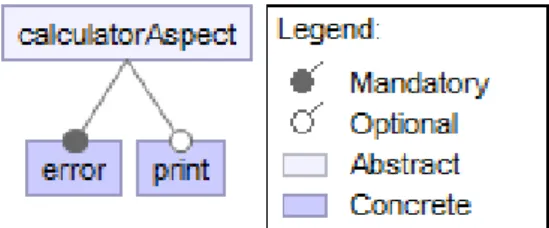
Figure 1: Features supported by Calculator Product Line (CPL)
Figure 2: Aspects captured in Calculator Product Line (CPL)
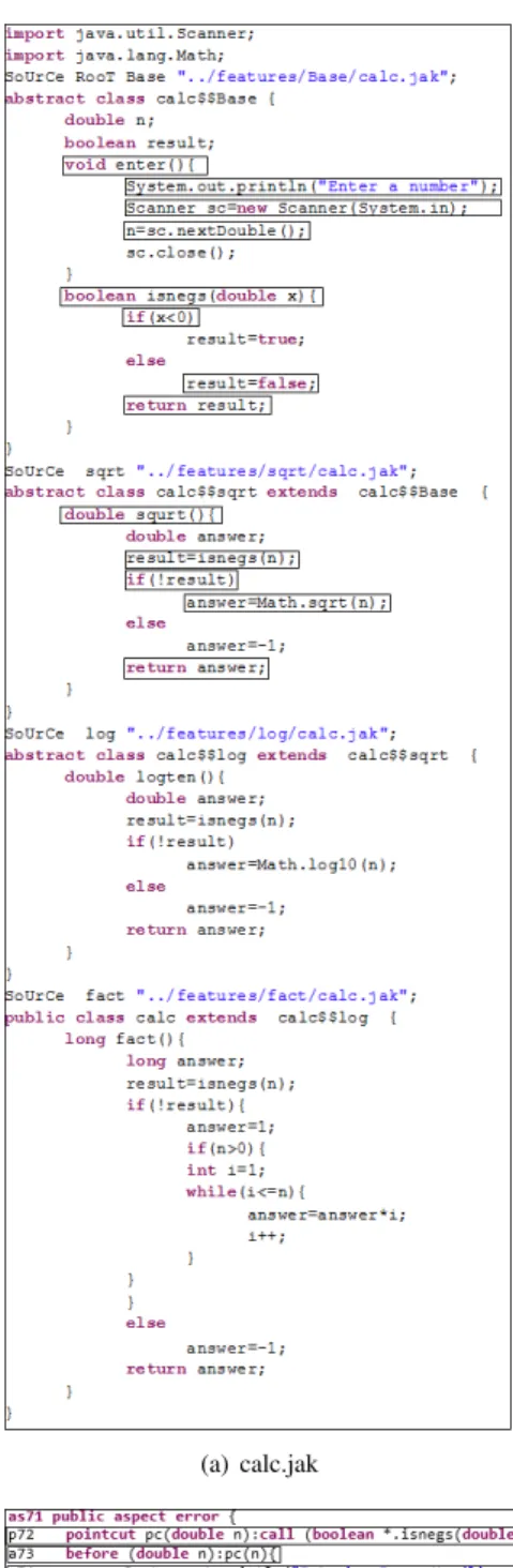
Example 2.1. Calculator Product Line (CPL) [45]: This program calculates the factorial, square root and logarith-mic value with base 10 of a number. This program is re-ferred to as Calculator Product Line (CPL).
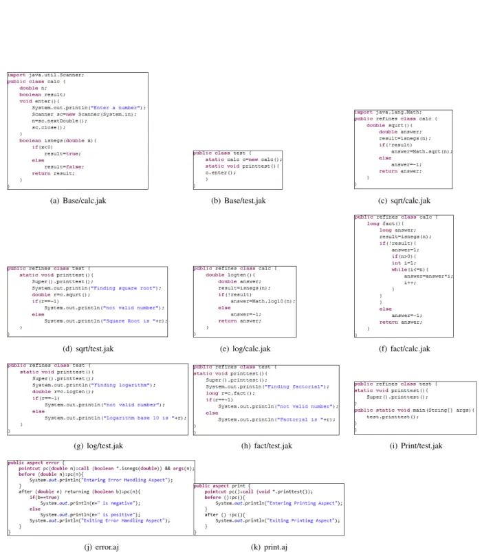
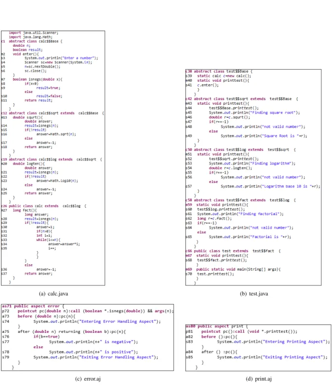
A feature-tree depicts various features supported by a product line in a hierarchical manner. The feature-tree for Example 2.1 is given in Figure 1. The various aspects that are captured for Example 2.1 are given in Figure 2. Figure 3 depicts the source code for each feature given in Figure 1 and each aspect given in Figure 2. Figure 4(a) – Figure 4(b) show the resultant files generated after the composition of all features.
2.2
Problems in feature-oriented
programming (FOP)
Feature-oriented programming (FOP) suffers from many problems in modularization of crosscutting concerns [3, 4, 5]. The presence of these problems leads to degradation in modularity of program family members and also decrease in maintainability, customizability, and evolvability. Some of the problems of FOP are discussed below.
1. FOP is unable to express dynamic crosscutting con-cernsthat affect the control flow of a program. It can only express static crosscutting concerns that affect the structure of the program. AOP languages can han-dle dynamic crosscutting concerns in an efficient man-ner through the use of pointcuts, advices etc.
2. FOP languages support onlyheterogeneous crosscut-ting concernswhere different join points are provided with different pieces of codes. In contrast, AOP lan-guages support homogeneous crosscutting concerns
where different join points are provided with the same piece of code.
3. FOP suffers from excessive method extension prob-lem when a feature crosscuts a large fraction of exist-ing classes because of refinements. A lot of methods are to be overridden for each method on which a cross-cut depends. This is because FOP is unable to modu-larize homogeneous crosscutting concerns. AOP uses wildcards in pointcuts to deal with this problem.
2.3
AOP extensions to FOP
AOP can be used to solve the above problems of FOP by in-tegrating AOP language features like wildcards, pointcuts, and advices into FOP languages. The different approaches used for integrating AOP language features into FOP lan-guages areMulti Mixins,Aspectual Mixin Layers, Aspec-tual Mixins. More details about these approaches can be found in [5, 3, 4]. TheAspectual Mixin Layersapproach is a popular one amongst all the approaches since this ap-proach overcomes all the aforementioned problems. Other approaches overcome some of the problems. We have used the approach of aspectual mixin layers in our work. We have separated the aspects from mixin layers for easy un-derstanding of our approach. Our mixin layers contain only a set of classes. Aspects are designed as different layers.
2.4
Program slicing
Program slicing is a technique which is employed to ana-lyze the behavior of a program on the basis of dependencies that exist between various statements. It takes out state-ments from a program related to a specific computation. The extracted statements constitute a slice. Thus, a slicing criterion is employed to compute a slice. A slicing crite-rion consists of a statements(or location in the program) and a variablev(or set of variables), and it is represented as a tuple< s, v >. Program slicing technique can be ei-ther staticordynamicbased on the input to the program. A program slicing technique is said to bestaticwhen it ex-tracts all the statements from a program with respect to a slicing criterion irrespective of the input to the program. On the other hand, a program slicing technique is said to bedynamicwhen all the statements from a program are ex-tracted with respect to a slicing criterion for aspecificinput to the program.
(a) Base/calc.jak (b) Base/test.jak (c) sqrt/calc.jak
(d) sqrt/test.jak (e) log/calc.jak (f) fact/calc.jak
(g) log/test.jak (h) fact/test.jak (i) Print/test.jak
(j) error.aj (k) print.aj
(a) calc.java (b) test.java
(c) error.aj (d) print.aj
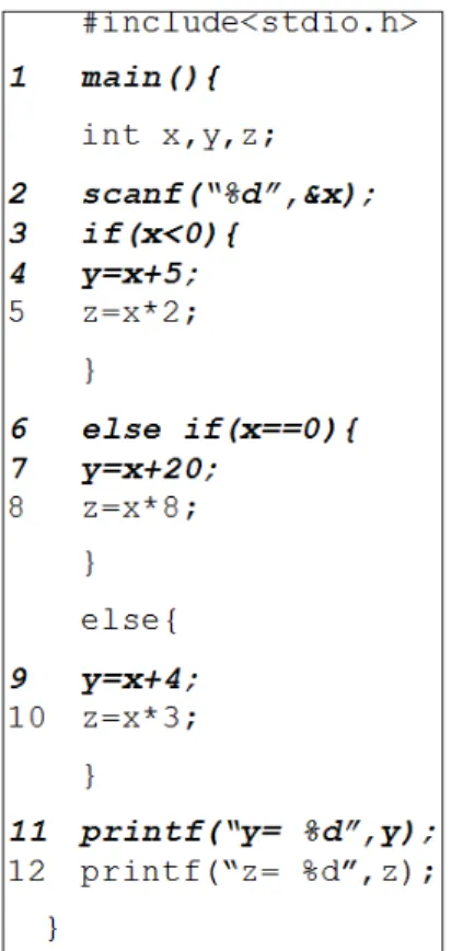
Figure 5: An example C program
Figure 6: Static slice with respect to slicing criterion <
11, y >
Figure 7: Dynamic slice with respect to slicing criterion
<{x= 10},11, y >
[10, 11, 12, 14, 15, 16, 17, 19, 21, 25, 26, 37, 38, 42]. For the details of the intermediate program representations and different slicing algorithms, the readers may refer to [10, 11, 12, 14, 15, 16, 17, 19, 21, 25, 26, 37, 38, 42]. In the next section, we propose an intermediate program representation for feature-oriented programs, on which our slicing algorithm can be applied.
3
Composite feature-aspect
dependence graph (CFADG): an
intermediate representation for
feature-oriented programs
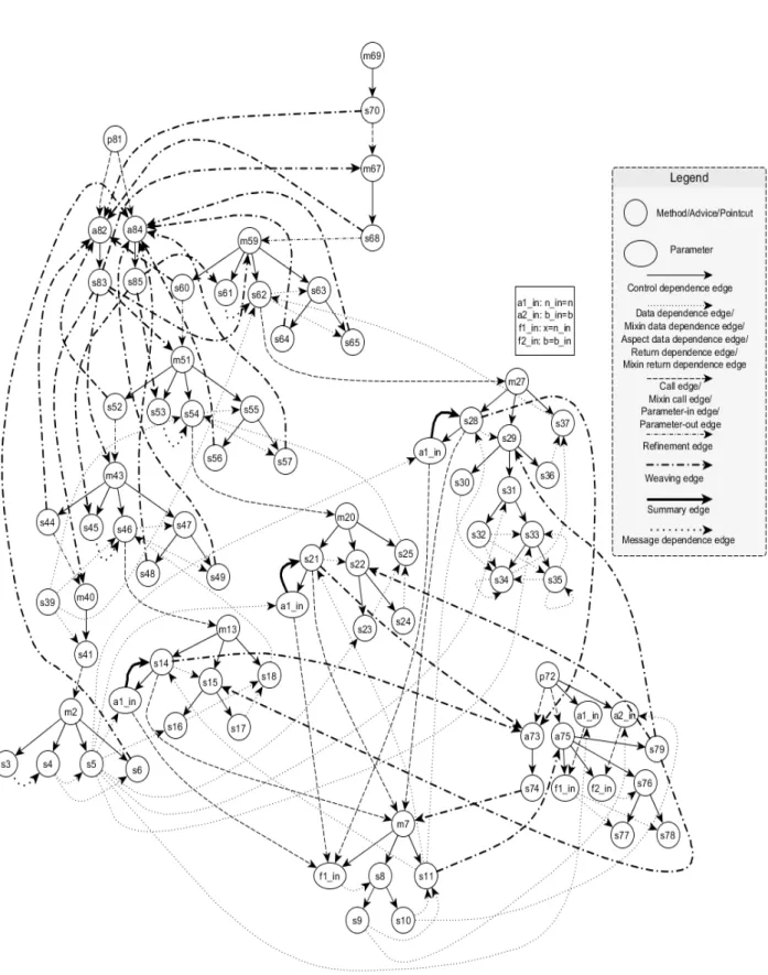
Figure 3. The square box with a1_in: n_in=n etc. speci-fies the actual and formal parameters. For example: a1_in: n_in=n specifies that nis an actual-in parameter. Simi-larly, a2_in: b_in=b specifies thatbis an actual-in param-eter, f1_in: x=n_in specifies thatxis a formal-in parame-ter, f2_in: b=b_in specifies thatbis a formal-in parameter. These notations are adopted from Horwitz et al. [47]. The construction of CFADG consists of the following steps:
– Constructing Procedure Dependence Graph (PDG) for each method in a mixin.
– Constructing Mixin Dependence Graph (MxDG) for each mixin.
– Constructing System Dependence Graph (SDG) for each mixin layer.
– Constructing Advice Dependence Graph (ADG) for each advice.
– Constructing Introduction Dependence Graph (IDG) for each introduction.
– Constructing Pointcut Dependence Graph (PtDG) for each pointcut.
– Constructing Aspect Dependence Graph (AsDG) for each aspect.
– Constructing Composite Feature Aspect Dependence Graph (CFADG) by combining all the SDGs and As-DGs.
Below, we briefly explain the steps for constructing the CFADG and the pseudocode.
(1) Construction of Procedure Dependence Graph (PDG)
A procedure dependence graph (PDG) depicts the control and data dependence relationships that exist between the statements in a program with only one function/method/procedure. The nodes in the graph correspond to the program statements and edges cor-respond to the dependence relationships between the statements.
(2) Construction of Mixin Dependence Graph (MxDG)
Amixin dependence graph (MxDG) is used to cap-ture all dependencies within a mixin. A MxDG has amixin entry vertex that connects the method entry vertex of each method in the mixin by amixin mem-bership edge. Each method entry in the MxDG is associated with formal-in and formal-out parameter nodes. The interactions among methods in a mixin occur by calling each other. This effect of method calls is symbolized by acallnode in a MxDG. Actual-inandactual-outparameter nodes are created at each call node corresponding to formal-in and formal-out
parameter nodes. The effect of returnstatements in a MxDG is represented by joining each returnnode to its correspondingcallnode through areturn depen-dence edge.
(3) Construction of System Dependence Graph (SDG) for each Mixin Layer
A single mixin layer may contain more than one mixin. A mixin may derive another mixin through inheritance. The MxDG for the derived class is con-structed. The mixin membership edges connect the mixin entry vertex of derived class to the method en-try vertices of all those methods that are defined and inherited in the derived class. The SDG for a mixin layer is constructed by joining all the mixin depen-dence graphs for that mixin layer through parameter edges, call edges and summary edges.
(4) Construction of Advice Dependence Graph (ADG)
Anadvice dependence graph(ADG) represents an ad-vice in an aspect. The statements or predicates in the advice are represented as vertices and dependen-cies amongst statements are represented as edges in an ADG. Each ADG is associated with a unique ver-tex calledadvice start vertexto signify entry into the advice.
(5) Construction of Introduction Dependence Graph (IDG)
An introduction dependence graph(IDG) represents an introduction in an aspect. If an introduction is a method or constructor, then its IDG is similar to PDG of a method. A unique vertex, calledintroduction start vertex, is used in IDG to signify the entry into the in-troduction.
(6) Construction of Pointcut Dependence Graph (PtDG)
Pointcuts in an aspect contain no body. Therefore, to represent pointcuts, only apointcut start vertexis cre-ated to denote the entry into the pointcut.
(7) Construction of Aspect Dependence Graph (AsDG)
Anaspect dependence graph(AsDG) is used to rep-resent a single aspect. It consists of a collection of ADGs, IDGs, PtDGs that are connected by some spe-cial kinds of edges. Each AsDG is associated with a unique vertex called aspect start vertex, to repre-sent entry into the aspect. Anaspect membership edge
is used to represent the membership relationships be-tween an aspect and its members. This edge connects the aspect start vertex to each start vertex of an ADG, IDG or PtDG. Each pointcut start vertex is connected to its corresponding advice start vertex by call edges.
The CFADG is constructed by combining the SDGs for all mixin layers present in the composition and the AsDGs through special kinds of edges. The SDGs for all mixin layers in a composition are connected us-ing refinement edges, mixin call edges, mixin data de-pendence edges, and mixin return dede-pendence edges. The AsDGs are connected to all the SDGs through weaving edges and aspect data dependence edges. The mixin membership edges and aspect membership edges along with mixin start vertices and aspect start vertices are removed during construction of CFADG. The CFADG for the program given in Figure 3 is shown in Figure 8. A CFADG contains the following types of edges:
(a) Control dependence edge: A control depen-dence edge in a CFADG from a noden1 to a
node n2 indicates that either node n2 is under
the scope of noden1or noden1controls the
ex-ecution of noden2where noden1is a predicate
node.
In Figure 8, edge(m20, s21)is a control depen-dence edge.
(b) Data dependence edge: A data dependence edgein a CFADG from a noden1to a noden2
indicates that noden2uses a variable that is
as-signed a value at noden1orn1creates an object
oandois used atn2.
In Figure 8, edges (s21, s22), (s39, s41),
(p72, a73)are data dependence edges.
(c) Mixin data dependence edge:Amixin data de-pendence edgein a CFADG from a noden1to a
noden2 indicates that noden2in a mixin layer
defines a variable which is used at noden1in
an-other mixin layer.
In Figure 8, edges(s5, s16)and(s39, s54)are mixin data dependence edges.
(d) Aspect data dependence edge:Anaspect data dependence edgein a CFADG from a noden1
to a noden2indicates that noden2in an aspect
uses the value of a variable and that variable is defined at noden1in a mixin.
In Figure 8, edge(s5, a1_in)is an aspect data dependence edge.
(e) Call edge: Acall edgein CFADG from a node
n1 to a node n2 indicates that noden1 calls a
method defined at noden2. Both the nodesn1
andn2are in same mixin layer.
In Figure 8, edge(s41, m2)is a call edge. (f) Mixin call edge: Amixin call edgein CFADG
from a noden1to a noden2indicates that node
n1in a mixin layer calls a method that is defined
in a different mixin layer at noden2.
In Figure 8, edge(s28, m7)is a mixin call edge. (g) Return dependence edge:Areturn dependence edgein a CFADG from noden1to noden2
in-dicates that noden1 in a mixin layer returns a
value to node n2 in the same mixin layer and
noden2calls a method where noden1is present.
In Figure 8, edge(s18, s46)is a return depen-dence edge.
(h) Mixin return dependence edge: A mixin re-turn dependence edgein a CFADG from noden1
to noden2 indicates that noden1in one mixin
layer returns a value to noden2in another mixin
layer and noden2calls a method where noden1
is present.
In Figure 8, edge(s11, s21)is a mixin return de-pendence edge.
(i) Parameter-in edge: Parameter-in edge in CFADG is added from actual-in parameters to corresponding formal-in parameters to indicate the receipt of values from the calling method to the called method.
In Figure 8, edges (s14 → a1_in, m7 →
f1_in), (s21 → a1_in, m7 → f1_in), and
(s28 → a1_in, m7 → f1_in)are parameter-in edges.
(j) Parameter-out edge: Parameter-out edge is added from formal-out parameters to corre-sponding actual-out parameters to indicate the return of values from the called method to the calling method. If an actual parameter is mod-ified inside a method, then the modmod-ified value becomes an actual-out parameter and the origi-nal value becomes an actual-in parameter. The parameter used to hold the value of actual-in pa-rameter in method definition becomes a formal-in parameter and the parameter used to hold the modified value becomes a formal-out parameter. In Figure 8, there are no parameter-out edges, since, in our example, no parameter is modified inside a method.
(k) Summary edge: Thesummary edgeis used to represent the transitive flow of dependence be-tween an in parameter node and an actual-out parameter node if the value of the actual-in parameter node affects the value of the corre-sponding actual-out vertex.
In Figure 8, edges(s14→a1_in, s14),(s21→
a1_in, s21), and(s28→ a1_in, s28)are sum-mary edges.
(l) Message dependence edge: A message depen-dence edge from a noden1to another noden2in
a dependency graph signifies that noden1
repre-sents a statement outputting some message with-out using any variable and node n2 represents
an input statement, a computation statement, a method call statement, or a predicate statement. In Figure 8, there exists a message dependence edge (s3, s4). Similarly, edges (s45, s46),
(m) Refinement edge: A refinement edge in a CFADG from a noden1to a noden2indicates
that noden1in child mixin layer calls a method
k()by prefacingSuper()call andk()is defined at noden2in parent mixin layer.
In Figure 8, the edge(s44, m40)is a refinement edge. Similarly, edges(s68, m59),(s60, m51), and(s52, m43)are refinement edges.
(n) Weaving edge:A weaving edge from a noden1
to noden2indicates that
– node n1 is a method call node and node
n2 is a before advice node capturing the
method called atn1and noden2 executes
before the method called by n1 executes.
OR
– noden1 is the last statement inbefore
ad-vice and noden2is the method entry node
of the method captured by the advice and node n2 executes after node n1 executes.
OR
– noden2is anafteradvice node and noden1
is the last statement in the method captured by noden2and noden2executes after node
n1executes. OR
– noden1is the last statement in anafter
ad-vice and noden2is the statement followed
by method call node and the method is cap-tured by the advice and node n1 executes
before noden2executes.
In Figure 8, edge(s14, a73)is a weaving edge. The brief pseudocode for constructing the CFADG for a feature-oriented program is given below, and the complete algorithm is given in Algorithm 8 in Appendix A.
CFADG construction Algorithm
(1) For each mixin layer
(a) For each mixin
i. Create mixin entry vertex ii. For each method
A. Compute control and data dependences. B. Construct PDG using control & data dependence
edges. iii. For each method call
A. Create actual parameter vertices. iv. For each method definition
A. Create method entry vertex. B. Create formal parameter vertices.
v. Construct MxDG by connecting all PDGs through method call edges, parameter edges and summary edges and connecting each method vertex to mixin start vertex through mixin membership edges. (b) Construct SDG by connecting all MxDGs through method
call edges, parameter edges.
(2) For each aspect
(a) Create aspect entry vertex. (b) For each advice
i. Create advice start vertex.
ii. Compute control and data dependences.
iii. Construct ADG using control & data dependence edges.
(c) For each introduction
i. Create introduction start vertex. ii. If introduction is a field then
Do not create any dependence graph. Else if introduction is a method then
Construct IDG using control and data dependence edges.
(d) For each pointcut
i. Create pointcut start vertex. ii. Construct PtDG.
(e) Construct AsDG by connecting advice start vertices, intro-duction start vertices, pointcut start vertices to aspect start vertex through aspect membership edges.
(3) Remove mixin membership edges, aspect membership edges, mixin start vertices, and aspect start vertices.
(4) Connect all SDGs through refinement edges, mixin call edges, mixin data dependence edges, and mixin return dependence edges.
(5) Connect all AsDGs to all SDGs through weaving and aspect data dependence edges.
4
Feature-aspect node-marking
dynamic slicing (FANMDS)
algorithm
In this section, we present our proposed algorithm for com-puting dynamic slices of feature-oriented programs using CFADG. We have named our algorithm Feature-Aspect Node-Marking Dynamic Slicing(FANMDS) algorithm as it is based on marking and unmarking the nodes of CFADG. Before presenting our FANMDS algorithm, we first intro-duce some definitions which will be used in our algorithm.
4.1
Definitions
Definition 1: Defn(v): Letv be a variable or an object in programP. A nodeuin the CFADG is said to beDef n(v)
node ifucorresponds to a definition statement that defines a value to variablevorurepresents a statement that creates objectv.
In the CFADG given in Figure 8, nodess23, ands24 rep-resentDefn(answer)nodes in the methodlogten()in mixin
calcinlogmixin layer.
Definition 2: DefnSet(v):The set of allDef n(v)nodes is referred to asDef nSet(v).
In the CFADG given in Figure 8, Def nSet(answer) =
{s23, s24} in the method logten() in mixin calc in log
mixin layer.
Definition 3: RecDefn(v):For each variablev,
RecDef n(v) represents the node corresponding to the most recent definition of v with respect to some point s
In the CFADG of Figure 8, RecDef n(i) is at statement
s32before while loop and it is at statements35during ex-ecution of while loop.
Definition 4: Usage(v):Letvbe a variable or an object in programP. A nodeuin the CFADG is said to beU sage(v)
node if urepresents a statement that uses the variable v
orurepresents a statement that uses the objectvto call a method on that object or to assign the objectvwith another object.
In the CFADG given in Figure 8, nodess47, ands49 rep-resentU sage(r)nodes. Similarly, nodes77, ands78are
U sage(n)nodes.
Definition 5: UsageSet(v):The set of allU se(v)nodes is referred to asU sageSet(v).
In the CFADG given in Figure 8, and U sageSet(r) =
{s47, s49},U sageSet(n) ={s77, s78}.
4.2
Overview of FANMDS algorithm
Before execution of a feature-oriented program F P, the features required for composition and the aspects to be cap-tured are selected. Then, the selected features are com-posed and selected aspects are weaved. The CFADG is constructed statically only once based on the composition of selected features and weaving of selected aspects. The program is executed for a specified input. The executed nodes in CFADG are marked and unmarked during pro-gram execution depending upon the arise and cease of de-pendences respectively. When a statement executes a Su-per() node, it is marked by the algorithm. Also the cor-responding method entry node, the associated actual and formal parameter nodes are marked. When there is an invo-cation of a method, the corresponding call node, the corre-sponding method entry node, the associated actual and for-mal parameter nodes are also marked. Whenever a pointcut is executed, the corresponding advice nodes are marked. When an advice is executed, the corresponding formal pa-rameter nodes are marked. During execution, the dynamic slice of each executed statement is computed. After execu-tion of each node and computaexecu-tion of dynamic slice at that node, the algorithm unmarks it.
Letdyn_slice(u)denote the dynamic slice with respect to the most recent execution of nodeu. Let(e1, u),
(e2, u), . . . ,(ek, u)be all the marked predecessor nodes of
uin the CFADG after execution of nodeu. The dynamic slice with respect to the present execution of nodeuis com-puted as
dyn_slice(u) ={u, e1, e2, . . . , ek} ∪dyn_slice(e1)∪
dyn_slice(e2)∪. . .∪dyn_slice(ek).
Our FANMDS algorithm computes the dynamic slice with respect to the specified slicing criterion by simply looking up the corresponding dyn_slice computed dur-ing run-time. Below, we present the pseudocode of our FANMDS algorithm in brief. Algorithm 9 in Appendix B presents our FANMDS algorithm in detail.
Feature-Aspect Node-Marking Dynamic Slicing (FAN-MDS) Algorithm
(1) CFADG Construction: Construct the CFADG for the given feature-oriented program with aspect-oriented extensions, statically only once.
(2) Initialization:Do the followings before each execution ofF P.
(a) Unmark all nodes of CFADG.
(b) Setdyn_slice(u) =φfor every nodeu.
(c) SetRecDef n(v) = N U LLfor every variablevof the programF P.
(3) Run time updations:Execute the program for the given set of in-put values and carry out the followings after each statementsof the programF Pis executed. Let nodeuin CFADG corresponds to the statementsin the programF P.
(a) For every variablevused at nodeu,
Update dyn_slice(u) = {u, e1, e2, . . . , ek} ∪
dyn_slice(e1)∪dyn_slice(e2)∪. . .∪dyn_slice(xk)
wheree1,e2, . . . ,ekare the marked predecessor nodes ofu
in CFADG.
(b) Ifuisdef n(v)node, then
i. Unmark the nodeRecDef n(v). ii. UpdateRecDef n(v) =u. (c) Mark nodeu.
(d) Ifuis amethod callnode ornewoperator node or polymor-phicnode ormixin callnode, then
i. Mark nodeu.
ii. Mark the associatedactual-in andactual-out nodes corresponding to the present execution ofu. iii. Mark the correspondingmethod entry node for the
present execution ofu.
iv. Mark the associatedformal-inandformal-out parame-ter nodes.
(e) Ifuis aSuper()method node i. Mark nodeu.
ii. Mark the associatedactual-in andactual-out nodes corresponding to the present execution ofu. iii. Mark the correspondingmethod entrynode present in
the parent mixin layer for the present execution ofu. iv. Mark theformal-inandformal-outparameter nodes
as-sociated with themethod entrynode. (f) Ifuis apointcutnode
i. Mark nodeu.
ii. Mark the correspondingadvicenodes for present exe-cution ofu.
(g) Ifuis anadvicenode i. Mark nodeu.
ii. Mark theformal-inandformal-outparameter nodes as-sociated with theadvicenode.
(h) Ifuis anintroductionnode such thatuis a method i. Mark nodeu.
ii. Mark theformal-inandformal-outparameter nodes. (i) Ifuis anintroductionnode such thatuis a field
i. Mark nodeu.
ii. Mark the node that defines a value toufor the current execution ofu.
iii. Mark the node that uses the value ofufor the current execution ofu.
(4) Slice Look Up
(a) For a given slicing command
i. Look updyn_slice(u)for variablevfor the content of the slice.
ii. Map the Java statements included in the computed dy-namic slice to the corresponding composed Jak state-ments to get the final dynamic slice
iii. Display the resulting slice.
(b) If the program has not terminated, go to Step 3.
Working of the Algorithm
The working of FANMDS algorithm is illustrated through an example. Consider the feature-oriented pro-gram given in Figure 3 and the selected features for com-position and aspects given in Figure 1 and Figure 2 respec-tively. After the composition of the selected features, the files that are generated are depicted in Figure 4. The corre-sponding CFADG is shown in Figure 8. During the initial-ization step, our algorithm first unmarks all the nodes of the CFADG and setsdyn_slice(u) =φfor every nodeuof the CFADG. Now, for the input datan= 5, the program will execute the statementsm69,s70,p81,a82,s83,m67,s68,
a82,s83,m59,s60,a82,s83,m51,s52,a82,s83,m43,
s44, a82,s83, s39, m40, s41,m2, s3, s4, s5,s6,a84,
s85,s45,s46,m13,s14,p72,a73,s74,m7,s8,s10,s11,
a75,s76,a78,s79,s15,s16,s18,s47,s49,a84,s85,s53,
s54,m20,s21,a73,s74,m7,s8,s10,s11,a75,s76,s78,
s79,s22,s23,s25,s55,s57,a84,s85,s61,s62,m27,s28,
a73,s74,m7,s8,s10,s11,a75,s76,s78,s79,s29,s30,
s31,s32,s33,s34,s35,s37,s63,s65,a84,s85,a84,s85
in order. So, our FANMDS algorithm marks these nodes. Our algorithm also marks the associated actual parameter vertices at the calling method and the formal parameter ver-tices at the called method.
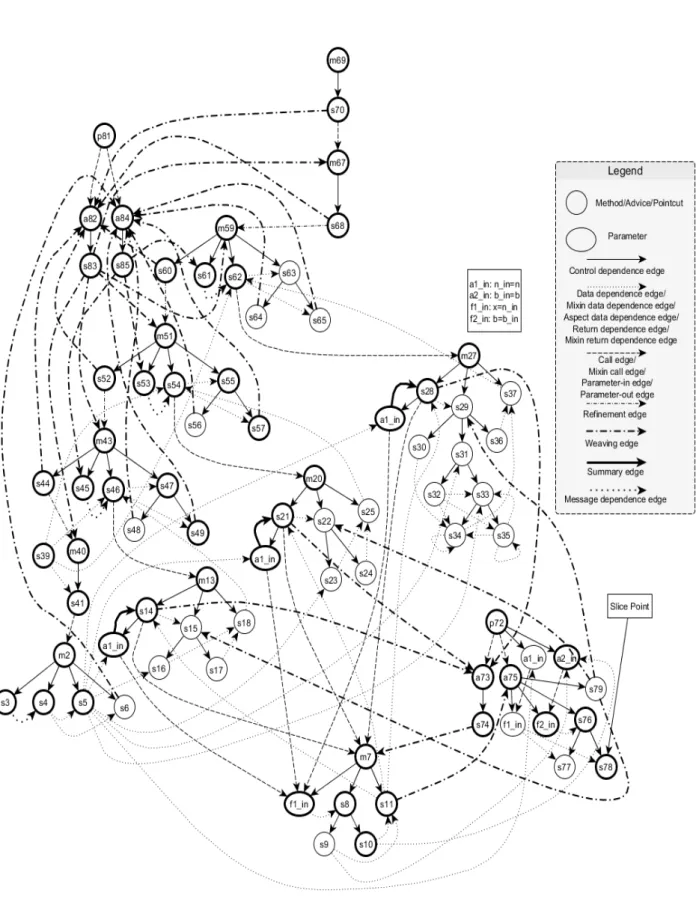
Now, the dynamic slice is to be computed with respect to variablenat statements78, i.e., with respect to slicing criterion<{n= 5}, s78, n >by traversing the CFADG in backward manner. According to the FANMDS algorithm, the dynamic slice with respect to variablen at statement
s78is given by the expression
dyn_slice(s78) = {s78, s76, a75 → f1_in} ∪
dyn_slice(s76)
∪dyn_slice(a75→f1_in).
By evaluating the above expression in a recursive manner, we get the final dynamic slice consisting of the statements corresponding to the nodesm2,s3,s4,s5,m7, s8,s10,
s11,m13,s14,m20,s21,m27,s28,s39,m40,s41,m43,
s44, s45, s46, s47, s49, m51, s52, s53, s54, s55, s57,
m59,s60,s61,s62,m67,s68,m69,s70,p72,a73,s74,
a75, s76, s78,p81,a82, s83, a84,s85. These are indi-cated as bold vertices in Figure 9 and the corresponding statements are indicated in rectangular boxes in Figure 10. Similarly, dynamic slice with respect to any slicing crite-rion can be computed using FANMDS algorithm.
5
Implementation
This section briefly describes the implementation of FAN-MDS algorithm. A dynamic slicing tool has been devel-oped to implement the algorithm which has been named
feature-aspect dynamic slicing tool (FADST). Figure 11 depicts the architectural design of the slicing tool FADST. The working of our slicing tool is depicted in Figure 12, through a flow chart.
In Figure 11, the executable components are depicted in rectangular boxes and the passive components are de-picted in ellipses. First, the features required to compose and aspects to be captured are selected. The selected fea-tures, the selected aspects, and the slicing criterion con-sisting of input, line number, and variable are provided to FADST through theGraphical User Interface(GUI) com-ponent. TheDynamic Slicercomponent interacts with the GUI component and produces the required result as output back to GUI. TheAHEAD composer[2] composes the se-lected features to generate a set of Java programs. These Java programs and the selected aspects are fed toAspectJ composer. AspectJ composer weaves the aspects at the ap-propriate join points, and the result is a composed AspectJ program. Thelexical analyzercomponent reads the com-posed AspectJ program and generates tokens from these programs. Upon encountering a useful token, the lexical analyzer component returns the token along with its type to theparser and semantic analyzercomponent. Theparser and semantic analyzercomponent takes the token and ana-lyzes it using the grammatical rules designed for the input programs.
Thecode instrumentorcomponent instruments the com-posed AspectJ programs. The classes are instrumented with line numbers prefixed with c, the aspects are instru-mented with line numbers prefixed withas, the methods are instrumented with line numbers prefixed with m, the pointcuts are instrumented with line numbers prefixed with
p, the advices are instrumented with line numbers prefixed witha, and the statements containing assignments, com-putations, predicates are instrumented with line numbers prefixed withs.
The CFADG constructor component constructs the CFADG using the required program analysis information such as type of statement, sets of variables defined or used at a statement etc. Thedynamic slicercomponent imple-ments the FANMDS algorithm. We have used Java lan-guage for our implementation. A compiler writing tool,
ANTLR (Another Tool for Language Recognition)5, has been used for lexical analyzer,parser and semantic ana-lyzercomponents of FADST.
An adjacency matrixadj[][]has been used for stor-ing the CFADG with respect to a selected composition of features of the given feature-oriented program.
Arrays are used to store the sets Defn(v), Usage(v),
RecDefn(v), anddyn_slice(u).
(a) calc.jak (b) test.jak
(c) error.aj (d) print.aj
Figure 11: Architecture of the slicing tool
Figure 12: Flowchart for working of the slicing tool given in Figure 11
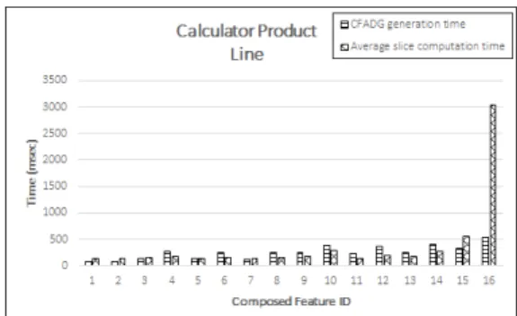
Figure 13: CFADG generation time and Average slice com-putation time for Calculator Product Line
5.1
Case studies and experimental results
We have applied our algorithm to some product lines6,7. We have also taken some open-source Java programs8 9 10. We have developed few product lines by identifying vari-ous features and converting these available Java programs into corresponding Jak programs. It may be noted that Jak is one of the feature-oriented programming languages. We have also taken the models of few product lines (such as calculator product line, stack product line, graph product line) from the work of different researchers [45, 44, 43, 46] and developed the corresponding Jak programs. These may be considered as representative feature-oriented programs with aspect-oriented extensions. In all the product lines, we have identified the aspects that are scattered through-out the program. The product lines we have taken as our case studies have various features and aspects which can be used for composing a variety of software product lines. We have taken fifteen product lines as our case studies. The characteristics of our software product lines are depicted in Table 1. These programs are executed for different compo-sitions of features with different aspects weaved for differ-ent inputs. Also, the algorithm has been tested for differdiffer-ent slicing criteria for different compositions of features and different inputs.
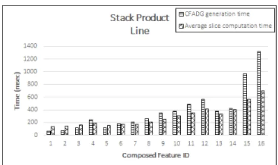
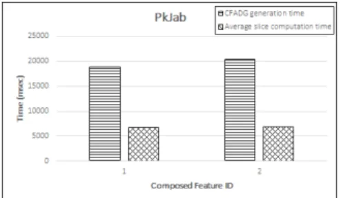
The CFADG generation time and average slice compu-tation time for various compositions of features in different product lines are depicted in Figures 13–27.
It can be inferred from Figures 13–27 that different com-positions of features result in different slice computation times. The aspects weaved at more number of join points take more time than the aspects weaved at less number of join points. For example, in Calculator Product Line
(CPL), the number of join points where the aspectPrintis weaved is more than that of aspectError. That’s why the slice computation time for the program wherePrintaspect
6http://spl2go.cs.ovgu.de/projects
7http://www.infosun.fim.uni-passau.de/spl/ apel/fh
8http://www.sanfoundry.com/ java-program-implement-avl-tree/
9http://www.geeksforgeeks.org/ avl-tree-set-2-deletion/
Figure 14: CFADG generation time and Average slice com-putation time for Stack Product Line
Figure 15: CFADG generation time and Average slice com-putation time for Graph Product Line
Figure 16: CFADG generation time and Average slice com-putation time for AVL Tree Product Line
Figure
17:
CF
ADG
generation
time
and
A
v
erage
slice
computation
time
for
Single
Link
ed
List
Product
Figure 18: CFADG generation time and Average slice com-putation time for DesktopSearcher
Figure 19: CFADG generation time and Average slice com-putation time for TankWar
Figure 20: CFADG generation time and Average slice com-putation time for GPL
Figure 21: CFADG generation time and Average slice com-putation time for MobileMedia
Figure 22: CFADG generation time and Average slice com-putation time for Digraph
Figure 23: CFADG generation time and Average slice com-putation time for Elevator
Figure 24: CFADG generation time and Average slice com-putation time for Vistex
Figure 26: CFADG generation time and Average slice com-putation time for Notepad
Figure 27: CFADG generation time and Average slice com-putation time for PkJab
is weaved is more than that of the program whereError as-pect is weaved. The features containing more number of loops take more time. The composed features containing less number of executable statements take less time com-pared to those containing more number of executable state-ments.
6
Comparison with related work
Several works have been carried out on slicing of procedure-oriented programs [34, 32, 33, 30, 47], object-oriented programs [11, 21, 39, 22, 15], aspect-object-oriented pro-grams [37, 9, 10, 16, 18, 23]. But very, few work have been carried out on slicing of feature-oriented programs [35].
Zhao [9] was the first to develop a two-phase slicing algorithm to compute static slices of aspect-oriented pro-grams. Later, Zhao et al. [10] developed an efficient algo-rithm for constructing system dependence graph for aspect-oriented programs. Ray et al. [16] developed an algo-rithm to compute dynamic slices of aspect-oriented pro-grams by constructingAspect System Dependence Graph
(AOSG). They had introduced a new logical node called C-node to capture communication dependencies among the non-aspect code and aspect code. They had also intro-duced a new arc calledaspect-membership arcto connect the dependence graphs of the non-aspect code and aspect code. They had not shown the actual parameters in the pointcuts. Singh et al. [18] proposed a method to com-pute slices depending upon the slice point location in the program. Their computed slice was an executable slice. Munjal et al. [23] automated the generation of system de-pendence graphs (SDG) for aspect-oriented programs by
analysing the bytecode of aspect-oriented programs. Then, they proposed a three-phase slicing algorithm to compute static slices using the intermediate graph for a given aspect-oriented program. All the above works [9, 15, 16, 18, 23] have not considered feature-oriented programs.
Apel et al. [3] presented a novel language for FOP in C++ namely FeatureC++. They also mentioned few prob-lems of FOP languages. Apel et al. [4] demonstrated FeatureC++ along with its adaptation to Aspect-Oriented Programming (AOP) concepts. They discussed the use of FeatureC++ in solving various problems related to incre-mental software development using AOP concepts. They also discussed the weaknesses of FOP for modularization of crosscutting concerns. Apel et al. [5] discussed the lim-itations of crosscutting modularity and the missing support of C++. They also focused on solutions for ease evolv-ability of software. Batory [2] presented basic concepts of FOP and a subset of the tools of the Algebraic Hier-archical Equations for Application Design(AHEAD) tool suite. Apel et al. [7] presented an overview of feature-oriented software development (FOSD) process. They had identified various key issues in different phases of FOSD. Thum et al. [6] developed an open source framework for FOSD namely FeatureIDE that supported all phases of FOSD along with support for feature-oriented pro-gramming languages, and delta-oriented propro-gramming lan-guages, aspect-oriented programming languages. Pereira et al. [20] discussed the findings of SPL management tools from a Systematic Literature Review (SLR). These works [7, 5, 3, 4, 2, 20, 6] discussed only the programming and development aspects of FOP and did not consider the slic-ing aspects. We have presented a technique for dynamic slicing of feature-oriented programs with aspect-oriented extensions using Jak as the FOP language.
Very few work have been carried out on slicing of feature-oriented programs [35]. Sahu et al. [35] suggested a technique to compute dynamic slices of feature-oriented programs. Their technique first composed the selected fea-tures of feature-oriented programs. Then, they used an exe-cution trace file and a dependence-based program represen-tation namelydynamic feature-oriented dependence graph
file. We do not use any execution trace file. During exe-cution of the program for a given input, the dynamic slice for each statement is computed by marking and unmarking process. Thus, there is no requirement of any execution trace file for storing the executed statements. So, our pro-posed approach does not take any extra time to read from or write into the execution trace file, thereby reducing the slice extraction time. Also, we have considered the aspects that are scattered throughout the code. Our algorithm does not create any new node in the intermediate representation CFADG during runtime. This results in faster computation of slices.
7
Conclusion and future work
We have presented an approach to compute dynamic slices of feature-oriented programs with aspect-oriented exten-sions. The features required for composition are first se-lected and composed usingAlgebraic Hierarchical Equa-tions for Application Design (AHEAD)composer. Then, the aspects are weaved into the generated composed Java program usingAspectJ composer to produce the resultant AspectJ program. The intermediate dependence based rep-resentation of the program containing Jak code and AspectJ code is constructed and it is called Composite Feature-Aspect Dependence Graph (CFADG). The program is exe-cuted for an input. During execution, the nodes of CFADG are marked and unmarked according to ourfeature-aspect node marking dynamic slicing(FANMDS) algorithm. We have developed a tool to implement our FANMDS algo-rithm and named it FADST. Our tool FADST computes the dynamic slices and the average slice extraction times for various compositions of features and aspects weaved for various product lines. Currently, our tool is able to han-dle various compositions for few product lines with few aspects captured. Also, current evaluation only uses prim-itive feature-oriented programs. In future, we will extend our tool to handle more number of product lines with more number of compositions.
Our algorithm may easily be extended to compute dy-namic slices of other feature-oriented languages like Fea-tureC++, FeatureRuby, FeatureHouse, Fuji, etc. Also, the extension of the algorithm can be used to compute con-ditioned slices, amorphous slices for feature-oriented pro-grams with various aspects captured. We will also find out the differences in the performance of different aspects.
References
[1] Christian Prehofer (1997) Feature-Oriented Program-ming: A Fresh Look at Objects, Proceedings of 11th European Conference on Object-Oriented Programming (ECOOP), Springer, Berlin, Hei-delberg, pp. 419–443. https://doi.org/10. 1007/bfb0053389
[2] Don Batory (2006) A Tutorial on Feature–Oriented Programming and the AHEAD Tool Suite, Proceed-ings of the 2005 International Conference on Gen-erative and Transformational Techniques in Software Engineering (GTTSE’05), Springer–Verlag, Berlin, Heidelberg, pp. 3–35. https://doi.org/10. 1007/11877028_1
[3] Sven Apel and Thomas Leich and Marko Rosen-muller and Gunter Saake (2005) FeatureC++: Feature-Oriented and Aspect-Oriented Programming in C++, Tech. rep., Department of Computer Science, Otto-von-Guericke University, Magdeburg, Germany.
[4] Sven Apel and Thomas Leich and Marko Rosen-muller and Gunter Saake (2005) FeatureC++: On the Symbiosis of Feature-Oriented and Aspect-Oriented ProgrammingProceedings of the International Con-ference on Generative Programming and Compo-nent Engineering (GPCE’05), Springer, pp. 125–140. https://doi.org/10.1007/11561347_10
[5] Sven Apel and Thomas Leich and Marko Rosen-muller and Gunter Saake (2005) Combining Feature-Oriented and Aspect-Feature-Oriented Programming to Sup-port Software Evolution, Proceedings of the 2nd ECOOP Workshop on Reflection, AOP and Meta-Data for Software Evolution (RAM-SE), School of Computer Science, University of Magdeburg, July, pp. 3–16.
[6] Thomas Thum and Christian Kastner and Fabian Benduhn and Jens Meinicke and Gunter Saake and Thomas Leich (2014) FeatureIDE: An ex-tensible framework for feature-oriented software development, Science of Computer Programming, 79, pp. 70–85. https://doi.org/10.1016/ j.scico.2012.06.002
[7] Sven Apel and Christian Kastner (2009) An Overview of Feature-Oriented Software Develop-ment. Journal of Object Technology, 8(5), pp. 49–84, July–August. https://doi.org/10. 5381/jot.2009.8.5.c5
[8] Gregor Kiczales and John Irwin and John Lamp-ing and Jean Marc LoLamp-ingtier and Cristiana Videira Lopes and Chris Maeda and Anurag Mendhekar (1997) Aspect-Oriented Programming, Proceedings of the European Conference on Object-Oriented Pro-gramming (ECOOP), Finland, June, pp. 220–242. https://doi.org/10.1007/bfb0053381
[10] Jianjun Zhao and Martin Rinard (2003) System De-pendence Graph Construction for Aspect-Oriented Programs. Technical report, Laboratory for Com-puter Science, Massachusetts Institute of Technology, USA, March.
[11] Loren Larsen and Mary Jean Harrold (1996) Slic-ing Object-Oriented Software, Proceedings of 18th International Conference on Software Engineering, pp. 495–505, March. https://doi.org/10. 1109/icse.1996.493444
[12] Timon Ter Braak (2006) Extending Program Slicing in Aspect–Oriented Programming With Inter–Type Declarations,5th TSConIT Program, June.
[13] Aspect Oriented Programming. www.wikipedia.org.
[14] Hiralal Agrawal and Joseph R. Horgan (1990) Dy-namic Program Slicing, ACM SIGPLAN Notices,
Proceedings of the ACM SIGPLAN 1990 conference on Programming language design and implementa-tion PLDI’90, 25(6), pp. 246–256, June. https: //doi.org/10.1145/93542.93576
[15] Durga Prasad Mohapatra and Rajib Mall and Rajeev Kumar (2004) An Edge Marking Tech-nique for Dynamic Slicing of Object-Oriented Pro-grams, Proceedings of the 28th Annual Interna-tional Computer Software and Applications Confer-ence (COMPSAC’04). https://doi.org/10. 1109/cmpsac.2004.1342806
[16] Abhisek Ray and Siba Mishra and Durga Prasad Mo-hapatra (2012) A Novel Approach for Computing Dynamic Slices of Aspect-Oriented Programs, Inter-national Journal of Computer Information Systems, 5(3),pp. 6–12, September.
[17] Abhisek Ray and Siba Mishra and Durga Prasad Mo-hapatra (2013) An Approach for Computing Dynamic Slice of Concurrent Aspect-Oriented Programs Inter-national Journal of Software Engineering and Its Ap-plications, 7(1), pp. 13–32, January.
[18] Jagannath Singh and Durga Prasad Mohapatra (2013) A Unique Aspect-Oriented Program Slicing Tech-nique, Proceedings of International Conference on Advances in Computing, Communications and Infor-matics (ICACCI’13), pp. 159–164.https://doi. org/10.1109/icacci.2013.6637164
[19] Jagannath Singh and Dishant Munjal and Durga Prasad Mohapatra (2014) Context Sensitive Dynamic slicing of Concurrent Aspect-Oriented Programs,
Proceedings of 21st Asia-Pacific Software Engineer-ing Conference (APSEC’14), pp. 167–174.https: //doi.org/10.1109/apsec.2014.35
[20] Juliana Alves Pereira and Kattiana Constantino and Eduardo Figueiredo (2015) A Systematic Litera-ture Review of Software Product Line Management Tools, Proceeddings of 14th International Confer-ence on Software Reuse (ICSR’15), Berlin Heidel-berg, pp. 73–89.https://doi.org/10.1007/ 978-3-319-14130-5_6
[21] Durga Prasad Mohapatra and Rajeev Kumar and Rajib Mall and D. S. Kumar and Mayank Bhasin (2006) Distributed dynamic slicing of Java pro-grams, Journal of Systems and Software, 79(12), pp. 1661–1678. https://doi.org/10.1016/ j.jss.2006.01.009
[22] Durga Prasad Mohapatra and Rajib Mall and Ra-jeev Kumar (2005) Computing dynamic slices of concurrent object-oriented programs, Information & Software Technology, 47(12), pp. 805–817. https://doi.org/10.1016/j.infsof. 2005.02.002
[23] Dishant Munjal and Jagannath Singh and Subhrakanta Panda and Durga Prasad Moha-patra (2015) Automated Slicing of Aspect-Oriented Programs using Bytecode Analysis,
Proceedings of IEEE 39th Annual International Computers, Software & Applications Confer-ence (COMPSAC 2015), pp. 191–199. https: //doi.org/10.1109/compsac.2015.98
[24] Madhusmita Sahu and Durga Prasad Mohapatra (2007) A Node-Marking Technique for Dynamic Slicing of Aspect-Oriented Programs,Proceedings of 10th International Conference on Information Tech-nology (ICIT 2007), pp. 155–160.https://doi. org/10.1109/icit.2007.70
[25] Diganta Goswami and Rajib Mall (1999) Fast Slicing of Concurrent Programs, Proceedings of 6th Inter-national Conference on High Performance Comput-ing (HiPC 1999), pp. 38–42.https://doi.org/ 10.1007/978-3-540-46642-0_6
[26] Diganta Goswami and Rajib Mall (2000) Dynamic Slicing of Concurrent Programs,Proceedings of 7th International Conference on High Performance Com-puting (HiPC 2000), pp. 15–26. https://doi. org/10.1007/3-540-44467-x_2
[27] Jaiprakash T. Lallchandani and Rajib Mall (2011) A Dynamic Slicing Technique for UML Architectural Models, IEEE Transactions on Software Engineer-ing, 37(6), pp. 737–771.https://doi.org/10. 1109/tse.2010.112
[29] Jaiprakash T. Lallchandani and Rajib Mall (2010) Integrated state-based dynamic slicing technique for UML models, IET Software, 4(1), pp. 55– 78. https://doi.org/10.1049/iet-sen. 2009.0080
[30] G. B. Mund and Rajib Mall (2006) An efficient in-terprocedural dynamic slicing method, The Journal of Systems and Software, 79, pp. 791–806.https: //doi.org/10.1016/j.jss.2005.07.024
[31] Diganta Goswami and Rajib Mall (2004) A parallel algorithm for static slicing of concurrent programs,
Concurrency – Practice and Experience, 16(8), pp. 751–769. https://doi.org/10.1002/cpe. 789
[32] G. B. Mund and R. Mall and S. Sarkar (2003) Computation of intraprocedural dynamic program slices,Information and Software Technology, 45 (8), pp. 499–512. https://doi.org/10.1016/ S0950-5849(03)00029-6
[33] G. B. Mund and R. Mall and S. Sarkar (2002) An efficient dynamic program slicing technique,
Information and Software Technology, 44 (2), pp. 123–132. https://doi.org/10.1016/ s0950-5849(01)00224-5
[34] Diganta Goswami and Rajib Mall (2002) An ef-ficient method for computing dynamic program slices, Information Processing Letters, 81(2), pp. 111–117. https://doi.org/10.1016/ s0020-0190(01)00202-2
[35] Madhusmita Sahu and Durga Prasad Mohapatra (2016) Dynamic Slicing of Feature-Oriented Pro-grams,Proceedings of 3rd International Conference on Advanced Computing, Networking and Informat-ics (ICACNI 2015), pp. 381–388.https://doi. org/10.1007/978-81-322-2529-4_40
[36] Mark Weiser (1981) Program Slicing,Proceedings of the 5th International Conference on Software Engi-neering (ICSE), pp. 439–449. IEEE Computer Soci-ety, March.
[37] Durga Prasad Mohapatra and Madhusmita Sahu and Rajib Mall and Rajeev Kumar (2008) Dynamic Slicing of Aspect–Oriented Programs, Informatica, 32(3), pp. 261–274.
[38] Jaiprakash T. Lallchandani and Rajib Mall (2005) Computation of Dynamic Slices for Object-Oriented Concurrent Programs, Proceedings of Asia Pa-cific Software Engineering Conference (APSEC 2005), pp. 341–350. https://doi.org/10. 1109/apsec.2005.51
[39] Jianjum Zhao (1998) Dynamic Slicing of Object– Oriented Programs, Technical report, Information Processing Society of Japan, pp. 1–7, May.
[40] Sebastian Gunther and Sagar Sunkle (2009) Feature-Oriented Programming with Ruby. InProceedings of the First International Workshop on Feature-Oriented Software Development (FOSD’09), pp. 11–18, Octo-ber. https://doi.org/10.1145/1629716. 1629721
[41] Sebastian Gunther and Sagar Sunkle (2012) rbFea-tures: Feature-oriented programming with Ruby, Sci-ence of Computer Programming, 77(3), pp. 152– 173, March. https://doi.org/10.1016/j. scico.2010.12.007
[42] Bogdan Korel and Satish Yalamanchili (1994) For-ward Computation Of Dynamic Program Slices,
Proceedings of the 1994 ACM SIGSOFT interna-tional symposium on Software testing and analy-sis(ISSTA’94), pp. 66–79, August.https://doi. org/10.1145/186258.186514
[43] Sven Apel and Thomas Leich and Gunter Saake(2008) Aspectual Feature Modules,
IEEE Transactions On Software Engineer-ing, 34(2),pp. 162–180, March/April. https: //doi.org/10.1109/tse.2007.70770
[44] Jia Liu and Don Batory and Srinivas Nedunuri (2005) Modeling Interactions in Feature-Oriented Software Designs,Proceedings of International Conference on Feature Interactions in Telecommunications and Soft-ware Systems (ICFI 2005), pp. 178–197.
[45] Ian Adams and Sigmon Myers (2009) FOP and AOP: Benefits, Pitfalls and Potential for Interaction, pp. 1– 7.
[46] Sagar Sunkle and Marko Rosenmuller and Norbert Siegmund and Syed Saif ur Rahman and Gunter Saake and Sven Apel (2008) Features as First-class Entities-Toward a Better Representation of Features.
Proceedings of Workshop on Modularization, Com-position, and Generative Techniques for Product Line Engineering, pp. 27–34, October.
8
Appendices
A
Construction of CFADG
Algorithm 8Construction of CFADG
Input:The feature-oriented program containing aspects with selected required features and weaved aspects.
Output:The composite feature-aspect dependence graph (CFADG). 1: procedureCONSTRUCTPDG()
2: forstart of a methoddo
3: Createmethod entry node.
4: foreach executable statement in the programdo
5: Create a node. 6: for allnodes createddo
7: ifnoden2is under the scope of noden1then
8: Addcontrol dependence edgefromn1ton2,n1→n2.
9: ifnoden1controls the execution of noden2then
10: Addcontrol dependence edgefromn1ton2,n1→n2.
11: ifnoden2uses the value of a variable that is defined at node
n1then
12: Adddata dependence edgefromn1ton2,n1→n2.
13: procedureCONSTRUCTMXDG() 14: for allmethods in a mixindo
15: CallConstructPDG(). 16: forentry of a mixindo
17: Createmixin entry node.
18: foreach parameter present in the method calldo
19: Create anactual-inparameter node.
20: foreach parameter present in the method definitiondo
21: Create aformal-inparameter node.
22: foreach parameter in the method call that is modified inside the methoddo
23: Create anactual-outparameter node.
24: foreach actual-out parameter nodedo
25: Create correspondingformal-outparameter node. 26: for allnodes createddo
27: ifnodexcorresponds to mixin entry node and nodeyis a method entry nodethen
28: Addmixin membership edgefromxtoy,x→y. 29: ifnoden1 returns a value to the calling method at noden2
within a mixin layerthen
30: Addreturn dependence edgefromn1ton2,n1→n2.
31: ifnoden1calls a method that is defined at noden2within a
mixin layerthen
32: Addcall edgefromn1ton2,n1→n2.
33: ifnoden1calls a method that is defined at noden2within a
mixin layer by passing parametersthen
34: Addcall edgefromn1ton2,n1→n2.
35: Addparameter-in edgefrom actual-in parameter node to corresponding formal-in parameter node.
36: Addparameter-out edgefrom formal-out parameter node to corresponding actual-out parameter node.
37: ifnoden1is an actual-in parameter node and noden2is an
actual-out parameter node such that the value at noden1affects the
value at noden2then
38: Addsummary edgefromn1ton2,n1→n2.
39: procedureCONSTRUCTSDG() 40: for allmixins within a mixin layerdo
41: CallConstructMxDG. 42: for allnodes createddo
43: ifnodexis apolymorphic method callthen
44: Createpolymorphic choice vertex.
45: ifnodeyis a polymorphic choice vertexthen
46: Add acall edgefromxtoy,x→y
47: ifnodexis anewoperator node and nodeyis the correspond-ing constructor nodethen
48: Addcall edgefromn1ton2,n1→n2.
49: Addparameter-in edgefrom actual-in parameter node to corresponding formal-in parameter node.
51: Removemixin membership edges. 52: Removemixin entry nodes. 53: procedureCONSTRUCTADG() 54: forstart of an advicedo
55: Createadvice start vertex. 56: ifadvice contains parametersthen
57: Createformal-inandformal-outparameter nodes. 58: for allnodes createddo
59: ifnoden2is under the scope of noden1then
60: Addcontrol dependence edgefromn1ton2,n1→n2.
61: ifnoden1controls the execution of noden2then
62: Addcontrol dependence edgefromn1ton2,n1→n2.
63: ifnoden2uses the value of a variable that is defined at node
n1then
64: Adddata dependence edgefromn1ton2,n1→n2.
65: procedureCONSTRUCTIDG() 66: forentry of introductiondo
67: Createintroduction start vertex.
68: ifintroduction is a method or constructorthen
69: CallConstructPDG. 70: ifintroduction is a fieldthen
71: Do nothing.
72: procedureCONSTRUCTPTDG() 73: forentry of pointcutdo
74: Createpointcut start vertex. 75: ifpointcut contains parametersthen
76: Create actual-in and actual-out parameter nodes. 77: procedureCONSTRUCTASDG()
78: forentry of an aspectdo
79: Createaspect start vertex. 80: for alladvices in an aspectdo
81: CallConstructADG().
82: for allpointcuts in an aspectdo
83: CallConstructPtDG(). 84: for allintroductions in an aspectdo
85: CallConstructIDG(). 86: for allnodes createddo
87: ifnodexis aspect start vertexthen
88: ifnodeyis advice start vertexthen
89: Createaspect membership edgefromxtoy,x→y. 90: ifnodeyis pointcut start vertexthen
91: Createaspect membership edgefromxtoy,x→y. 92: ifnodeyis introduction start vertexthen
93: Createaspect membership edgefromxtoy,x→y. 94: ifnodexis pointcut start node and nodeyis advice start node
then
95: Createdata dependence edgefromxtoy,x→y. 96: Addparameter-in edgefrom actual-in parameter node to
corresponding formal-in parameter node.
97: Addparameter-out edgefrom formal-out parameter node to corresponding actual-out parameter node.
98: procedureCONSTRUCTCFADG() 99: foreach mixin layerdo
100: CallConstructSDG(). 101: foreach aspectdo
102: CallConstructAsDG. 103: for allnodes createddo
104: ifnoden2in one mixin layer uses the value of a variable that
is defined at noden1in different mixin layerthen
105: Addmixin data dependence edgefromn1ton2,n1→
n2.
106: ifnoden2in an aspect uses the value of a variable that is
defined at noden1in a mixinthen
107: Addaspect data dependence edgefromn1ton2,n1→
n2.
108: ifnoden1in one mixin layer returns a value to the calling
method at noden2in different mixin layerthen
109: Addmixin return dependence edgefromn1ton2,n1→
n2.
110: ifnoden1in one mixin layer calls a method that is defined
at noden2in different mixin layerthen
111: Addmixin call edgefromn1ton2,n1→n2.
112: Addparameter-inandparameter-out edges.
113: ifnoden1calls a method that is defined at noden2using
Super()methodthen
114: Addrefinement edgefromn1ton2,n1→n2.
115: ifnoden1is an output statement followed by noden2and
noden2 is an input, a computation, a predicate, or a method call
statementthen
116: Addmessage dependence edgefromn1 ton2,n1 →
n2.
117: ifnoden1 is a method call node and noden2is abefore
advice node capturing the method called atn1then
118: Addweaving edgefromn1ton2,n1→n2.
119: ifnoden1is the last statement in abeforeadvice and node
n2 is the method entry node of the method captured by the advice
then
120: Addweaving edgefromn1ton2,n1→n2.
121: ifnodey is anafteradvice node and noden1 is the last
statement in the method captured by noden2then
122: Addweaving edgefromn1ton2,n1→n2.
123: ifnoden1is the last statement in anafteradvice and node
n2is the statement followed by method call node and the method is
captured by the advicethen
124: Addweaving edgefromn1ton2,n1→n2.
B
Feature-aspect node-marking
dynamic slicing (FANMDS)
algorithm
Algorithm 9Feature-Aspect Node Marking Dynamic Slic-ing (FANMDS) Algorithm
INPUT:Composite Feature-Aspect Dependence Graph (CFADG) of the programF P, Slicing criterion< i, s, v >.
OUTPUT:List of nodes contained in required dynamic slice. 1: M arked=φ .Initially, unmark all nodes of CFADG.
2: Setdyn_slice(u) =φ . uis a node in CFADG.
3: SetRecDef n(v) =N U LL .v is a variable.
4: Execute the programF Pfor inputi. 5: whileF Pdoes not terminatedo
6: Updatedyn_slice(u) ={u, e1, e2, . . . , ek}∪dyn_slice(e1)∪
dyn_slice(e2)∪. . .∪dyn_slice(ek)
7: M arked=M arked∪ {u}. .Mark node u.
8: ifuis aDef n(v)nodethen
9: M arked=M arked\ {RecDef n(v)}. .Unmark the node RecDefn(v).
10: RecDef n(v) =u. .Update RecDefn(v).
11: ifuis amethod callnode for a methodMthen
12: panodeM=f(M, panode).
13: M eM=g(M, M e).
14: pf nodeM =h(M, pf node).
15: M arked=M arked∪ {u}. .Mark node u.
16: M arked=M arked∪panodeM. .Mark associated
actual parameter nodes.
17: M arked=M arked∪ {M eM}. .Mark corresponding
method entry node.
18: M arked=M arked∪pf nodeM. .Mark associated
formal parameter nodes.
19: ifuis anewoperatornode for a constructorMthen
20: panodeM=f(M, panode).
21: M eM=g(M, M e).
22: pf nodeM =h(M, pf node).
23: M arked=M arked∪ {u}. .Mark node u.
24: M arked=M arked∪panodeM. .Mark associated
actual parameter nodes.
25: M arked=M arked∪ {M eM}. .Mark corresponding
method entry node.
26: M arked=M arked∪pf nodeM. .Mark associated
formal parameter nodes.
27: ifuis apolymorphicnode for a virtual methodMthen
28: panodeM=f(M, panode).
29: M eM=g(M, M e).
30: pf nodeM=h(M, pf node).
31: M arked=M arked∪ {u}. .Mark nodeu.
32: M arked=M arked∪panodeM. .Mark associated
actual parameter nodes.
33: M arked=M arked∪ {M eM}. .Mark corresponding
method entry node.
34: M arked=M arked∪pf nodeM. .Mark associated
formal parameter nodes.
35: ifuis amixin callnode for a methodMthen
36: panodeM=f(M, panode).
37: M eM=g(M, M e).
38: pf nodeM=h(M, pf node).
39: M arked=M arked∪ {u}. .Mark node u.
40: M arked=M arked∪panodeM. .Mark associated
actual parameter nodes.
41: M arked=M arked∪ {M eM}. .Mark corresponding
method entry node.
42: M arked=M arked∪pf nodeM. .Mark associated
formal parameter nodes.
43: ifuis aSuper()method callnode for a methodMthen
44: M eM=h(M, M e).
45: M arked=M arked∪ {u}. .Mark node u.
46: M arked=M arked∪ {M eM}. .Mark corresponding
method entry node.
47: ifuis apointcutnodethen
48: badvP =x(P, badv).
49: aadvP=y(P, aadv).
50: panodeP =f(P, panode).
51: pf nodeM=g(M, pf node).
52: M arked=M arked∪ {u}. .Mark node u.
53: M arked=M arked∪panodeM. .Mark corresponding
actual parameter nodes.
54: M arked=M arked∪pf nodeM. .Mark corresponding
formal parameter nodes.
55: M arked=M arked∪badvP. .Mark the corresponding
before advice entry node.
56: M arked=M arked∪aadvP. .Mark the corresponding
after advice entry node.
57: ifuis anadviceentry node for an adviceAcorresponding to pointcutPthen
58: bbadvA=z(A, badvP).
59: baadvA=z(A, aadvP).
60: M arked=M arked\bbadvA.
61: M arked=M arked\baadvA. .Unmark all nodes in
body of advice corresponding to previous execution of u.
62: pf nodeM=g(M, pf node).
63: M arked=M arked\pf nodeM. .Unmark all the
64: ifuis anintroductionnode such thatuis a methodthen
65: M bM =k(M, M b).
66: M arked=M arked\M bM. .Unmark all the nodes in
the method body corresponding to previous execution of u.
67: pf nodeM =g(M, pf node).
68: M arked=M arked\pf nodeM. .Unmark all the
formal parameter nodes associated withucorresponding to previous execution of u.
69: ifvis method call node corresponding to previous execution ofuthen
70: M arked=M arked\v. .Unmark the method call node corresponding to previous execution of u.
71: panodev=f(v, panode).
72: M arked=M arked\panodev. .Unmark the
asso-ciated actual parameter nodes for a method call node corresponding to previous execution of u.
73: pf nodeM =h(M, pf node).
74: M arked=M arked∪ {u}. .Mark node u.
75: M arked=M arked∪pf nodeM. .Mark associated
formal parameter nodes.
76: ifuis anintroductionnode such thatuis a fieldthen
77: M arked=M arked∪ {Def n(v)}..Mark Defn(v) node.
78: M arked=M arked∪ {U sage(v)}. .Mark Usage(v) node.
79: ifuis amethod entrynode for a methodMthen
80: M bM =k(M, M b).
81: M arked=M arked\M bM. .Unmark all the nodes in
the method body corresponding to previous execution of u.
82: pf nodeM =g(M, pf node).
83: M arked=M arked\pf nodeM. .Unmark all the
formal parameter nodes associated withucorresponding to previous execution of u.
84: ifvis method call node corresponding to previous execution ofuthen
85: M arked=M arked\v. .Unmark the method call node corresponding to previous execution of u.
86: panodev=f(v, panode).
87: M arked=M arked\panodev. .Unmark the
asso-ciated actual parameter nodes for a method call node corresponding to previous execution of u.
88: ifuis amixin entrynode for a methodMthen
89: M bM =k(M, M b).
90: M arked=M arked\M bM. .Unmark all the nodes in
the method body corresponding to previous execution of u.
91: pf nodeM=g(M, pf node).
92: M arked=M arked\pf nodeM. .Unmark all the
formal parameter nodes associated withucorresponding to previous execution of u.
93: ifvis method call node corresponding to previous execution ofuthen
94: M arked=M arked\v. .Unmark the method call node corresponding to previous execution of u.
95: panodev=f(v, panode).
96: M arked=M arked\panodev. .Unmark the
asso-ciated actual parameter nodes for a method call node corresponding to previous execution of u.
97: ifuisnewoperator entrynode for a constructorMthen
98: M bM =k(M, M b).
99: M arked=M arked\M bM. .Unmark all the nodes in
the method body corresponding to previous execution of u.
100: pf nodeM =g(M, pf node).
101: M arked=M arked\pf nodeM. .Unmark all the
formal parameter nodes associated withucorresponding to previous execution of u.
102: ifvis method call node corresponding to previous execution ofuthen
103: M arked=M arked\v. .Unmark the method call node corresponding to previous execution of u.
104: panodev=f(v, panode).
105: M arked=M arked\panodev. .Unmark the
asso-ciated actual parameter nodes for a method call node corresponding to previous execution of u.
106: fora given slicing command< i, s, v >do
107: Look updyn_slice(u)for variablev. 108: Displaydyn_slice(u).
109: Map nodes indyn_slice(u)to corresponding statements in composed Java program.
110: Map statements included indyn_slice(u)in composed Java program to corresponding statements in composed Jak program. 111: Display statements included in dyn_slice(u)from