TECHNICAL UNIVERSITY OF CLUJ-NAPOCA
ACTA TECHNICA NAPOCENSIS
Series: Applied Mathematics, Mechanics, and Engineering Vol. 62, Issue IV, November, 2019
THEORETICAL ASPECTS REGARDING THE OPTIMIZED CONTROL OF
THE ELECTROMECHANICAL ACTUATORS USED IN THE FLOW
CONTROL
Mihai BANICA, Vasile NASUI, Flaviu-Nicolae KESUCZ
Abstract: The purpose of the scientific research in the present paper is to improve the operation of the thermal power plants, by optimizing the movement of the electromechanical actuators, which are integrated in the gas valve components, in terms of adapting to comfort, performance and maintenance requirements. Optimizing the system is to find new solutions for controlling the linear motion of the electromechanical actuators, including choosing some working principles and the order, which would become patent proposals, or new research stands.
Key words: AC regulator, actuator, ArduinoUNO, motion control, Proteus, simulation, softstarter
1. INTRODUCTION
Products using energy sources are subject to the EU Energy Efficiency Requirements (EUP). With the adoption of the 2005/32 EC Framework Directive in 2005, repealed in 2009 by Directive 2009/125, the EU regulator put the bases of specific "implementation measures" that affect a wide range of energy and energy products (EUP/ERP) products. Known as Eco Design, ErP (Energy related Products), aims to reduce energy consumption, as well as energy labeling of energy-using products by 2020.
The goal is to minimize the use of energy in the design phase and throughout production, packaging and transport. Products according to the measure simplification can be easily recognized as they will be CE marked. The CE marking will cover the relevant product safety requirements, as well as energy efficiency requirements, if any. The scope of the framework is very broad and covers all energy related products, except for means of transport. It also captures components which are intended to be incorporated into energy-consuming products. The conditions and criteria for selecting the new implementation measures are: significant environmental impact, coupled with
a large sales volume with a clear potential for improved performance without excessive cost.
In order to identify the first objectives of the implementation measures, the Commission relied on a network of consultants to launch a series of studies with stakeholder input.
Impact assessments have been carried out to determine proportionality. In a communication to the Council and the European Parliament, the Commission presented its work plan for the 2016÷2019 period, which includes 16 plans, the first and most important is the Construction of automatic control systems [13].
obtained theoretically due to their complexity and insufficient knowledge of the laws that determine the evolution of the phenomenon investigated.
For experimental research, it is specific to organize the unfolding of a phenomenon or process under known conditions, with the elimination of influences as much as possibility disturbing external ones, because by observing it and measuring the characteristic sizes, its mechanisms and the links between the factors are deduced.
Any technical or scientific activity is carried out by quantitative evaluation of some sizes, parameters or constant. The value of research results depends on the choice of the most appropriate means of investigation and terms of measurement.
All experimental research involves the measurement of mechanical or other magnitudes in a static or dynamic regime, variable in time or interdependence, using the apparatus and the appropriate means of measuring, processing the data obtained and finally establishing conclusions on the basis of which the results can be capitalized. Based on these results, improvement takes place technologies and existing equipment, the creation of new machines with superior performance, the discovery of new materials and technologies [8]. The boiler is a heat-generating plant, which is then distributed through a fluid thermal agent (water, steam, hot air, antifreeze).
Following the operation of the thermal power plants, certain problems were found which are deficient in time, namely:
−due to fluctuations in power supply voltage, some components in the boiler (electronic board, fan, gas valve, servomotors) during operation, suffer; −fluctuations of pressure and flow,
respectively, on the gas supply network, lead to problems in the parameters of the thermal power plants.
The scientific research work consists of finding new solutions for the control of the linear movement of the functioning of the electromechanical actuators from the gas vapor component used in the thermal power stations,
either powered by alternating voltage changers and electronic controller, which is a complex and logical circuit for optimal operation of peripheral equipment.
2. PROJECT DESCRIPTION
The paper presents the optimized control of actuators, which are in the field of mechanical engineering, mechatronic, which is a new, complex and multidisciplinary, as well as the design of a new prototype mechatronic system designed for the soft starter of the actuators used in the gas valve from the thermal power stations. It falls into the tendencies and national and international priorities and make both the theme and the research in this work to be topical. Mechatronics technology brings to mind the issue of information that is the toning component in relation to material and energy.
The concept of mechatronics defines an interdisciplinary integrative science. It appears as a necessity of the desire to improve the classical technical systems existing in all fields activity, resulting in simple, efficient, economical, reliable systems.
The multidisciplinary feature of this technology refers to the cross-border merger of engineering sciences, such as engineering mechanical engineering, electrical engineering, electronics and computer science. Mechatronics is the synergistic and systematic combination of mechanics, electronics and computer science in real time. Mechanics are a branch of a physicists studying how the position of bodies changes, a change called mechanical motion.
Founded by physicist Isaac Newton in his famous work “Philosophiae Naturalis Principia Classical Mechanics Mathematica” studies the laws of mechanical movement of macroscopic bodies moving at low speeds compared to the speed of light.
Statics studies the conditions in which the balance of bodies is achieved under the action of forces and couples, cinematic describes the mechanical movement neglecting the causes of this movement, and the dynamics establishes the laws of mechanical motion taking into account all the causes that can change the position of the bodies.
Electronics is a discipline in the field of applied physics, dealing with the study of electronic devices and circuits that include these elements (electronic circuits), used in ordering, adjusting, and measuring processes. The identification of the electron in 1897, together with the invention of the electronic tube, which could amplify and rectify the small electrical signals, has inaugurated electronics and the epoch of electrons.
Informatics comes from the addition of information and mathematics. Other sources say it comes from the combination of information and automation.
The history of computer science begins before the moment the emergence of the digital computer. The development of informatics in the early 1970s was marked by the emergence of the microprocessor, characterized by high reliability and flexibility, offering same time gauge and low price, all these have allowed the replacement of analogical and classical electronic elements, making electronic systems more complex but at the same time easier to use. Figure 1 shows the structural elements of a mechatronic system [12].
Fig.1. The structural elements of a mechatronic system
The surprising evolution recorded in the electronic and electrical field has facilitated the integration of these components into the existing mechanical structures, which have led to the simplification of the mechanical construction. Virtually many mechanical parts have been
replaced with more reliable, accurate, easy-to-maintain, cheap electronic systems. All these elements are essential in making the connection between the interface electromechanical and sensor system with hardware interface and control software.
Sensors (sensitive elements) provide the ability to retrieve information about the state of the system or process, the environment in which it operates changes in features functionalities of the device.
At the same time, they also allow decisions to command or discontinue the operation of systems in case of damage or under certain limit conditions. A great diversity of sensors can be placed on the mechanical structure or just some of its components, depending on the parameters of interest of the mechatronic system.
Introduction of software modules (computational algorithms for control, information flow, data acquisition, interface between the human operator and the prototype mechatronic system virtual, modeling, simulation, visualization) transforms the mechatronic system into an advanced, complex, automatic, flexible, intelligent system.
Flexibility is characterized by the ease of the system being adaptable to the changes that occur in its operating environment, this being possible by modifying control software.
Mechatronics is a specialization whose curriculum integrates disciplines focusing on mechanical engineering, electronics and engineering of hardware and software systems.
By actuator we understand a device that produces a mechanical work in response to an external signal. The command signal has a relatively low energy and can be voltage or current, pneumatic or hydraulic pressure. When it receives a command signal, an actuator responds by turning the power supply into mechanical motion. Actuators as elements of execution compatible with mechatronic technology have functional features such as: non-polluting, reliability, broad possibilities of motion regulation, safety in operation, constructive simplicity, high positioning accuracy, high yield and compactness.
In Figure 2 shows the basic structure of an actuator.
Fig.2. Basic structure of an actuator
An actuator can be defined with a pair of two transducers:
1.Transducer A - with the electrical input port;
2.Transducer B - with mechanical output port. The definition of an actuator is illustrated in Figure 3.
Fig.3. Defining an actuator
The conversion of the input energy (electric, thermal, magnetic, optical, chemical) into usable output energy and dissipated heat is achieved by means of electric, magnetic fields as a result of some physical phenomena (the interaction
between a magnetic field and current conductors, the piezoelectric phenomenon, the shape memory, electrohydraulic, diamagnetic effect) [9].
As this stunts work shows the improvement of the operation of the thermal power stations, respectively of the gas valves, by optimizing the movement of the electromechanical actuators, this can be achieved by:
−Variable Frequency Drive (VFD) is devices that generate alternating variable voltage electrical voltage. Using them can lead to significant savings of electricity, and also eliminating the current shock that occurs at the direct start;
−AC regulator, modify the voltage applied to the receiver, but the frequency remains constant and equal to that of the power supply and is used for the controlled power supply with electricity consumption of consumers in electro thermal applications, glass, ceramics, metallurgy, cement industry, as well as heating of the environment in the halls industrial.
Appropriate to the application domain, the command system is designed for output voltages with full or synced sine wave trains. The main operating parameters of the system (voltage charging, current charging, maximum voltage, maximum current, voltage and current regulators, maximum angle and minimum command) are stored in the EEPROM memory so they can be changed easily. Parameters can be changed according to the application requirements.
Supplying voltage to the AC regulator according to requirements load is very easy to modifying integration and proportionality constants [15].
The role of soft starter in electric drives contributes to a more economical production process, eliminating the mechanical and electrical wear of the equipment.
voltage drops and the occurrence of the circulation currents.
Preventing appearance such phenomena reduce the wear and tear of the mechanisms, allowing continuous operation of industrial processes for a long time. The soft starter of the gas valve and of the electromechanical actuators in the boiler section, in Figure 4 shows the block diagram of the electronic soft starter system [20].
Fig.4. Block diagram of the soft starter system
The advantages of this alternating voltage variation startup method are:
−controllable current at startup; − no power peaks;
−does not require maintenance;
−mechanical shocks and current shocks are avoided;
−gradualy increases voltage.
Thus, the undesired effects of sudden starts and stops are eliminated.
The starter software features are:
−the starting ramp is the time from which the voltage variation begins until it reaches the maximum value, the ramp time should not be longer than 3-5 seconds;
−the stop ramp is used when a soft stop is required. The stop ramp represents the time from the moment the voltage has the maximum value until the moment due to the drop in voltage, it reaches the initial value. If the time ramp is set to zero, then stopping will simply look like a direct stop. One advantage of soft starter is that it can be done with soft start and soft stop. Figure 5 shows the two ramps distinctively.
Fig.5. Voltage diagram, start-stop ramp [21]
3. EXPERIMENTAL RESULTS
The optimized control of the movement of the electromechanical actuators of the gas valve, made up of the thermal power stations, was achieved with a new variant single-phase AC regulator soft starter. The module was made in the first phase, on an open-source platform, with an Arduino UNO development plaque, the simulation being done in the Proteus v.8 software.
Proteus is free trial software from the Math&Scientific Tools subcategory. It is an application for modeling virtual systems and simulation of electronic circuits. The suite combines simulated mixed circuit simulation, animated components, and microprocessor models to facilitate co-simulation complete microcontroller models. Proteus also has the ability to simulate the interaction between software running on a microcontroller and any analog or digital electronics connected to it, simulates the input/output ports, interrupts, timers, and all other peripherals present on each supported processor.
The first Arduino was launched in 2005 with the aim of providing a cheap and simple solution for beginners and professionals to create devices capable of interacting with the environment using sensors and drive systems. The most common examples are devices for beginners such as: simple robots, thermostats, motion detectors, actuators. Arduino pads are commercially available in pre-assembled form or as home assemblies (DIY).
programming. Besides these also includes a huge community dedicated to creating and distributing projects that aim to create devices that can sense and control various activities or processes in the real world [3].
These boards provide the pines I/O user, called the General Purpose Input/ Output (GPIO) digital and analog port, which can be interfaced with a wide range of placards called shields or other electronic circuits specific to the embedded systems: sensors, buttons, LCD screen, relays, and the creation of new electronic projects.
The boards have serial communication interfaces, including USB on some models, to load programs from personal computers. To program microcontrollers, Arduino comes with a medium of Integrated Development (IDE) based on the Processing project, which includes support for programming languages like C and C++ using special rules for organizing the code. A microcontroller installed on Arduino comes pre-programmed with a bootloader that simplifies the loading of programs on the chip's flash memory compared to other devices that require external programmers.
This makes Arduino a simple solution, allowing programming from any ordinary computer. Currently, the bootloader optiboot is the default bootloader installed on Arduino UNO.
At the conceptual level, when using the Arduino integrated development environment, programming all the pads is done through serial connection.
Its implementation differs depending on the version hardware. Some Arduino placards have implemented logic level converters to convert RS-232 to TTL logic levels.
The current Arduino plates are programmed via USB, with integrated USB-serial conversion chips, such as the FTDI FT232. Some newer UNO models use a separate AVR chip programmed to function as a USB-to-serial converter, which can be reprogrammed through a dedicated ICSP port. Other variants, such as the Arduino Mini and the unofficial version of Boarduino, use USB-serial serial adapters, cables, Bluetooth, or other methods.
The Arduino Plateau has many of the microcontroller I/O pins exposed to be used by other circuits. Diecimila, Duemilanove and UNO offers 14 digital I/O pins, 6 of which can produce PWM signals and 6 analogue inputs that can also be used as digital inputs/outputs. These pins are accessible via the top of the tab through some mother-toe pins with 2.54 mm pins. Arduino programs can be written in any programming language with a compiler capable of producing a binary machine code. Atmel offers an environment of development for its microcontrollers, AVR Studio and more recently, Atmel Studio [4].
A program written in IDE for Arduino is called a sketch. Arduino IDE offers a software library called Wiring from the Wiring project, which offers many common input and output procedures. A typical C and C ++ Arduino sketch is composed of two functions that are compiled and linked to the main () program in an executable program with a cyclic execution: −setup (): a function that is run only once at the beginning of the program when the settings are initialized;
−loop (): a function called repeatedly until the platen power is turned off [1], [5]. If the source language is a high-level language, and the object language is a lower-level language (assembly language or machine code), then that translator is called a compiler. The process of compiling a program takes place in several phases. One phase is a unitary operation in which the source program is transformed from one representation to another.
The main phases of a compilation are those in Figure 6:
−lexical analysis: the source text is taken as a sequence of characters that are then grouped into entities called atoms; atoms are assigned lexical codes, so that at the exit of this phase, the source program appears as a sequence of such codes. Examples of atoms: keywords, identifiers, numeric constants, punctuation marks; −syntactic analysis: aims to group the
resulting atoms after lexical analysis in syntactic structures. A syntactic structure can be seen as a tree whose terminal nodes represent atoms, while inner nodes represent strings of atoms that form a logical entity. Examples of syntactical structures: phrases, instructions, statements;
−intermediate code generation, in this phase transformation of the syntax tree takes place in a sequence of simple instructions similar to the macroinstructions of an assembly language. The difference between the intermediate code and assembly language is mainly that the intermediate code does not specify the registers used in the operations. Examples of intermediate code representations: postfix notation, instructions with three addresses. The intermediate code has the advantage of being more optimized than the car code;
−code optimization is an optional phase whose role is to modify portions of the generated intermediate code so that the resulting program meets certain performance criteria targeting execution time and/ or memory space occupied; −generate the final code: Assume
transforming the intermediate code instructions (possibly optimized) into machine instructions (or assembly) for the target computer (the one to be executed compiled program);
−symbol table management, symbol table (TS) is a data structure designed to store information about the (name) symbols appearing in the source program; the
compiler makes reference to this table almost in all phases of compilation; −error handling, a compiler must be able to
recognize certain categories of errors that may occur in the source program; treating an error involves detecting it, issuing a message and recovering from error, that is, as much as possible, continuing the compilation process until the source text is depleted so that the number of compilers needed to eliminate all errors from a program to be as small as possible. Basically, there are errors specific to each compilation phase.
The compilation process is shown in Figure 7.
Fig.7. Beginning of compilation
The phases of a compilation process can in principle flow into two ways:
1. At the output of each phase, an intermediate file will be generated, containing the representation of the source program resulting in that phase, a file that will be the input for the next phase. In this case, at least one scroll of the source program will take place in each phase from the beginning to the end. Such a scroll is called passage; 2. Two or more compilation phases
intersect so that they are executed through a single pass. Applying one or both of these two ways depends on the nature of the compiled language and the environment in which the compiler is to run [16].
void setup() {
pinMode(9,OUTPUT); pinMode(10, OUTPUT); pinMode(11,OUTPUT); pinMode(12,OUTPUT; pinMode(13, OUTPUT); }
void loop() {
digitalWrite(13, HIGH); digitalWrite(12, LOW); digitalWrite(11, LOW); digitalWrite(10, LOW); digitalWrite( 9, LOW); delay(1000);
digitalWrite(13, HIGH); digitalWrite(12, HIGH); digitalWrite(11, LOW); digitalWrite(10, LOW); digitalWrite( 9, LOW); delay(1000);
digitalWrite(13, HIGH); digitalWrite(12, HIGH); digitalWrite(11, HIGH); digitalWrite(10, LOW); digitalWrite( 9, LOW); delay(1000); digitalWrite(13, HIGH); digitalWrite(12, HIGH); digitalWrite(11, HIGH); digitalWrite(10, HIGH); digitalWrite( 9, LOW); delay(1000);
digitalWrite(13, HIGH); digitalWrite(12, HIGH); digitalWrite(11, HIGH); digitalWrite(10, HIGH); digitalWrite( 9, HIGH); delay(1000) [11].
Figure 8 shows the schedule with scheduled times [6].
Fig.8. Timing chart
After compiling and linking to the GNU toolchain also included in the IDE, the Arduino development environment sends the command to the avrdude program to convert the executable code into a hexadecimal encoded text file that can be loaded into the Arduino UNO by a loader.
After converting the program, a hexadecimal encoded text file is displayed and is shown below:
:100000000C945C000C946E000C946E000C946E00CA :100010000C946E000C946E000C946E000C946E00A8 :100020000C946E000C946E000C946E000C946E0098 :100030000C946E000C946E000C946E000C946E0088 :100040000C9439010C946E000C946E000C946E00AC :100050000C946E000C946E000C946E000C946E0068 :100060000C946E000C946E00000000080002010069 :100070000003040700000000000000000000000072 :10008000250028002B0000000000240027002A0083 :10009000040404040404040402020202020203032E :1000A0000303030301020408102040800102040836 :1000B000102001020408102011241FBECFEFD8E049 :1000C000DEBFCDBF21E0A0E0B1E001C01D92A930AC :1000D000B207E1F70E9483010C944B020C940000DC :1000E00090E0FC01EC55FF4F2491FC01E057FF4FDD :1000F0008491882399F090E0880F991FFC01EA57BA :10010000FF4FA591B491FC01E458FF4F8591949164 :100110008FB7F894EC91E22BEC938FBF089590E0A9 :10012000FC01E859FF4F2491FC01EC55FF4F34913D :10013000FC01E057FF4FE491EE2309F43CC0222379 :1001400039F1233091F038F42130A9F0223001F553 :1001500084B58F7D12C0273091F02830A1F0243073 :10016000B9F4809180008F7D03C0809180008F77EB :10017000809380000DC084B58F7784BD09C08091C5 :10018000B0008F7703C08091B0008F7D8093B00066 :10019000F0E0EE0FFF1FE458FF4FA591B4919FB719 :1001A000F894611104C08C913095382302C0EC9111 :1001B0003E2B3C939FBF08953FB7F8948091050173 :1001C00090910601A0910701B091080126B5A89B66
:1001D00005C02F3F19F00196A11DB11D3FBFBA2FD9
:1003600080917A00846080937A0080917A00826024 :1003700080937A0080917A00816080937A008091E6 :100380007A00806880937A001092C1008DE00E940C :1003900070008CE00E9470008BE00E9470008AE088 :1003A0000E94700089E00E947000C0E0D0E061E02F :1003B0008DE00E948F0060E08CE00E948F0060E082 :1003C0008BE00E948F0060E08AE00E948F0060E076 :1003D00089E00E948F000E94010161E08DE00E948F :1003E0008F0061E08CE00E948F0060E08BE00E9453 :1003F0008F0060E08AE00E948F0060E089E00E9448 :100400008F000E94010161E08DE00E948F0061E099 :100410008CE00E948F0061E08BE00E948F0060E022 :100420008AE00E948F0060E089E00E948F000E94B5 :10043000010161E08DE00E948F0061E08CE00E948C :100440008F0061E08BE00E948F0061E08AE00E94F3 :100450008F0060E089E00E948F000E94010161E04E :100460008DE00E948F0061E08CE00E948F0061E0CF :100470008BE00E948F0061E08AE00E948F0061E0C3 :1004800089E00E948F000E940101209709F48FCF1C :0A0490000E9400008CCFF894FFCF0B
:00000001FF
The technical characteristics of the Arduino UNO development board are depicted in Figure 9 and include:
• Microcontroller: ATmega328p • USB Chip: CH340G
• Operating Voltage: 5V, Input Voltage: 5-12V • Digital I/O Pins: 14 (of which 6 PWM output) • Analog Input Pins: 6
• DC Current for 3.3V Pin: 50 mA
• Flash Memory: 32KB (ATmega328) of which 0.5 KB used by bootloader
• SRAM: 2 KB (ATmega328) • EEPROM: 1 KB (ATmega328) • Clock Speed: 16 MHz
Fig.9. Development board Arduino UNO
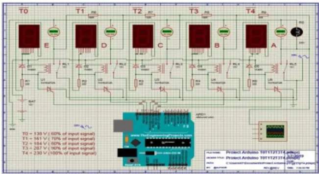
Figure 10 shows the simulation of the Arduino UNO development board with the Proteus v.8 software and in Figures 11÷15 the time simulation was performed: T0, T1, T2, T3, T4 which corresponds to the clock signal pulse of 1000ms.
Fig.10. Simulation of Arduino UNO development board with Proteus v.8 application
Fig.11. Simulation of Arduino UNO development board with Proteus v.8 application at time [T0]
Fig.12. Simulation of Arduino UNO development board with Proteus v.8 application at time [T1]
Fig.14. Simulation of Arduino UNO development board with Proteus v.8 application at time [T3]
Fig.15. Simulation of Arduino UNO development board with Proteus v.8 application at time [T4]
In this case, the resistive voltage dividers used to create reference voltages, or to reduce the amplitude of the voltage so that it can be measured, can be used as a low frequency signal attenuator and consists of two or more serially connected resistors, the output voltage being taken from one of the resistors.
The resistive voltage divider is shown in Figure 16.
Fig.16. Draws resistive voltage divider
where: Vin = input voltage to be insured; Vout = output voltage, proportional to the input voltage, measured on resistance R2 with a low
voltage device; R1 = the resistance to which most of the voltage or the high-voltage arm is applied; R2 = the resistance to which the residual voltage is applied and on which the low voltage device is connected.
Resistors of the divider are made of manganese and have the value of resistance high enough to have their own low consumption.
Such a splitter works correctly in DC and in low-frequency alternating current, where the parasitic elements of the resistors and the external circuit are negligible. A fraction of the applied stress falling on the R2 resistance will be calculated with the formula:
+ ∗ =
2 1
2
R R
R V
Vout in (1)
The equivalent resistance of the divider is equal to the parallel combination of the four resistors and is represented by the formula:
2 1
2 1
R R
R R Requiv
+ ∗
= (2)
The resistor group R6÷R9 represents the resistive voltage divider, known as a potential divider, is a passive linear circuit which produces a voltage output (VOUT), which is a fraction of the voltage input (VIN). The division of voltage is the result of distributing the input voltage between the divider components.
The four resistors connected in series with the input voltage applied to R6 and the output voltage collected from the point of interconnection between them (E, D, C. B, A) in turn with the impulse of the tact signal, obtained by programming the development board.
The Q0-Q4 command signal range is 1000ms and is applied to the T0-T4 group, T0 formed by the components (D1-rectifier diode, R1-resistor, RL1-relay, U1-thyristor, 7 Segment LED Display) they then arrive at the resistive voltage divider.
From the experimental calculation of the voltage divider, the following values of the output voltage were obtained:
ArduinoUNO plate, equivalent to 60% of the input voltage;
• T1 = 161V alternating current, which corresponds to pin Mode (12, OUTPUT), denoted Q1 at the output of the ArduinoUNO plate, equivalent to 70% of the input voltage;
• T2 = 184V alternating current, which corresponds topinMode (11, OUTPUT), denoted Q2 at the output of the ArduinoUNO plate, equivalent to 80% of the input voltage;
• T3 = 207V alternating current, which corresponds to pinMode (10, OUTPUT), denoted Q3 at the output of the ArduinoUNO plate equivalent to 90% of the input voltage;
• T4 = 230V alternating current, which corresponds to pinMode (9, OUTPUT), marked Q4 at the output of the ArduinoUNO plate, equivalent to 100% of the input voltage. T4 is basically a bypass between the input voltage and the output voltage applied to the load resistance (RS). In the libraries of the Proteus and Arduino software, the actuators studied do not exist as a database but have been replaced with a load resistance equal to the internal resistance of the actuators “RS 230V 650 OHM”. On the basis of the simulations performed, the single-phase AC regulator module in the soft starter version was also realized, which led to the optimization of the electromechanical actuators movement used in gas valve, consisting of thermal power stations.
4. CONCLUSIONS
In the course of this paper the general state of the art regarding the optimized control technique of the movement at the electromechanical actuators used in the thermal power stations was presented.
From the above, it can be noticed that the optimized control technique of the movement at the electromechanical actuators used at the thermal power plants has reached a special performance, but there is still a potentially significant innovations. Therefore, in the course
of successive works, new areas of research will be approached, with the intent to base interdisciplinary with the current technical state and based on data from experience, new operating principles.
The main contributions are:
−research to implement new multi-parametric control strategies;
−the approach of new original technical solutions for optimized linear motion control for electromechanical actuators. The prospects for further research are highlighted by the fact that there are multiple industrial applications, with the implications of diversified actuators.
5. REFERENCES
[1] Antal, T.A., Considerations on the serial PC-Arduino Uno R3 interaction, in Java, using JDeveloper, for a 3R serial robot,
based on the Ardulink library.
ActaTechnicaNapocensis, ISSN 1221-5872 Series: Applied Mathematics, Mechanics and Engineering, Vol.61, 2018, pp.8-9
[2] Arghir, M, Cimpan, M., Equipament
maintenance study, Acta Technica
Napocensis, Series: Applied Mathematics and Mechanics Vol. 56, 2013, pp.77-78 [3] Banzi, M., Shiloh, M., Getting Started
with Arduino, Maker Media, Inc., ISBN 978-1-4493-6333-8, Gravenstein Highway North, Sebastopol, CA 95472, USA, 2015, pp.18-22
[4] Boxall, J., Arduino Workshop, No Starch Press, Inc., ISBN 1-59327-448-3 San Francisco, 2013, pp.28-32
[5] Brian. W., Arduino Programming notebook, Creative Commons 171 Second Street, Suite 300 San Francisco, CA 94105, USA, 2007, pp.24-30
[6] Edmond, N., Belis, M., Măsuri electrice și electronice, Editura Didactică și Pedagogica, București, 1972, pp.380-384 [7] Kesucz, F., Banica, M., Nasui, V.,
Bulletin, Series C, Fascicle: Mechanics, Tribology, Machine Manufacturing Technology, ISSN 1224-3264, No. XXXII, 2018
[8] Năsui, V., Bazele cercetarii experimentale. Editura Universitatii de Nord Baia Mare, 2000
[9] Năsui, V., Optimizarea randamentului actuatorilor electromecanici, Editura Risoprint, Cluj-Napoca. ISBN 973-751-374-6, 2006, pp.3-4
[10] Pop, E, Stoica, V., Principii și metode de măsurare numerică. Editura Facla, Timișoara, 1977, pp.185-186.
[11] Riley, M., Programming Your Home,
ISBN-13: 978-1-93435-690-6 Raleigh, North Carolina, USA, 2012, pp. 216-218 [12] Vlasin, I., De la Mecatronica la Educație
Smart, U.T. Press Cluj-Napoca, ISBN 978-606-737-338-7, 2018, pp. 39-40
[13] ***https://2016.export.gov/European union/energyrelatedproducts/index.asp [14] ***https://arduino.cc
[15] ***http://www.creeaza.com/tehnologie/ electronica-electricitate/Variatorul-de- tensiune-alterna787.php
[16] ***http://labs.cs.upt.ro/labs/lft/html/ LFT00.htm
[17] ***http://www.electrozep.ro [18] ***https://www.elegoo.com [19] *** https://www.engie.ro
[20] ***https://www.elprocus.com/soft-starter-principle-working/
[21] ***http://www.rasfoiesc.com/inginerie/ electronica/Variatoare-de-tensiune-alterna58.php
[22] ***https://proteus.soft112.com
Aspecte teoretice privind controlul optimizat al actuatoarelor electromecanice folosite în reglarea debitului
Rezumat: Scopul cercetării științifice în lucrarea de față, este de îmbunătățire a funcționarii centralelor termice, prin optimizarea mișcării actuatoarelor electromecanice, ce sunt integrate în component vanelor de gaz, din punct de vedere al adaptării la cerințele de confort, randament, mentenanța și suportul de mentenanță. Optimizarea sistemului consta în găsirea de noi soluții de control a mișcării liniare a actuatoarelor electromecanice, inclusiv prin alegerea unor principii de lucru și comandă, care ar devenii propuneri de brevete de invenție, sau de noi standuri pentru cercetare.
Mihai BANICA, Associate Professor, Ph.D., Technical University of Cluj-Napoca, North University Center of Baia Mare, Department of Engineering and Management of Technology,
[email protected], Phone:+40 264 202 975, Str. Dr. Victor Babes 62A, Baia Mare,
Maramures, 430083, Romania
Vasile NASUI, Professor, Ph.D., Technical University of Cluj-Napoca, North University Center of Baia Mare, Department of Engineering and Management of Technology,
[email protected], Phone:+40 264 202 975, Str. Dr. Victor Babes 62A, Baia Mare,
Maramures, 430083, Romania
Flaviu-Nicolae KESUCZ, Ph.D. student, Technical University of Cluj-Napoca, North University Center of Baia Mare, Department of Engineering and Management of Technology,
[email protected], Phone:+40 264 202 975, Str. Dr. Victor Babes 62A, Baia