TECHNICALUNIVERSITY OF CLUJ-NAPOCA
ACTA TECHNICA NAPOCENSIS
Series: Applied Mathematics, Mechanics, and Engineering Vol. 61, Issue IV, November, 2018
AUTOMATING THE FEEDING OF A FUSE BOX FOR
THE AUTO INDUSTRY
Răzvan CURTA, Mihai STEOPAN, Claudiu SCHONSTEIN, Florin URSA
Abstract: The general objective of the presented paper was to design and make an automated system for
the feeding of a fuse box with automotive fuses, in order to decrease the number of the damaged fuses and to reduce the process time. To achieve this goal, we have focused on designing a simpler, cost-effective, easy-to-use and easily achievable mechanism with the purpose to be facile to implement within the industrial company. In order to design and model the concept, we used SolidWorks software and for the calculations for the motors and the ball-screw, the MathCad software was used. We took the concept from a type of Cartesian robot that is best suited to the requirements. Six Sigma methodology was used in the development stage of the product and finite element analyzes were performed to verify the structure of the automated system and to observe the strength of the used parts and the degree of their deformation.
Key words: Cartesian robot structure, CAD, Six Sigma, high productivity.
1. INTRODUCTION
A robot is a mobile mechatronic system - especially one programmable by a computer - designed to automate human interaction with the environment in which it evolves. The name "robot" was first used by Czech writer Karel Čapek in the 1920 play R.U.R. ("Rossum's Universal Robots") to denote a fictional humanoid and comes from a Czech word, robota, meaning "forced labor" [1,2].
Fig. 1: Unimate robot pouring coffee 1967 [5]
Into the driving force of development, electronics evolved as well with the occurrence of the first electronic autonomous robots created by William Grey Walter in Bristol, England in 1948, as well as Computer Numerical Control (CNC) machine tools in the late 1940s by Frank L. Stulen and John T. Parsons [3].
The first digital, programmable and commercial robot was constructed in 1954 by George Devol and it was named the Unimate. In 1961 it was sold to General Motors and it was used to lift pieces of hot metal from die casting machines [4,5].
Brief presentation of the subject
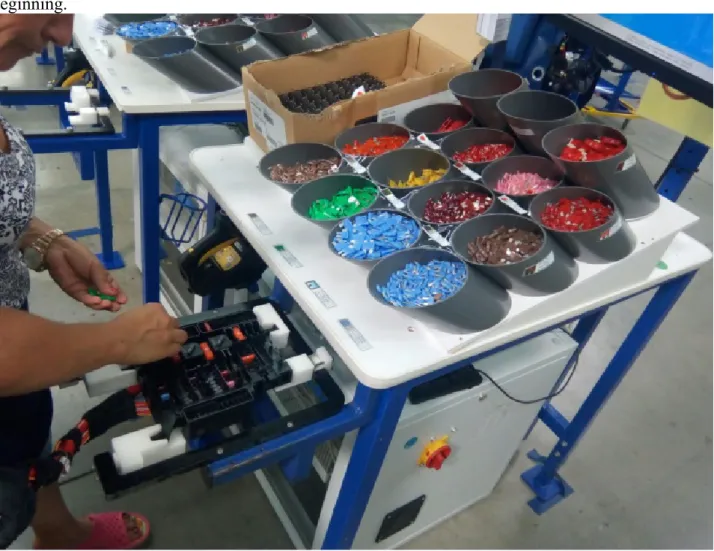
In this paper is presented the solution of a problem related to the feeding of a fuse box with automotive fuses for a car, within an industrial enterprise. At present, the population of the boxes with fuses is done by human operators as shown in Figure 2.
thus the operation needs to be restored from beginning.
Fig. 2: The current state of fuse mounting within the enterprise
The fuse population process starts by scanning a barcode containing all the wires that come on that wiring harness; after scanning, the monitor shows in which cavity the fuses should be inserted and which type of fuse should be inserted.
The operator takes the fuses from the place where they are stored, inserts them into the box and with a special device presses all the fuses to be arranged at the same height.
After all fuses have been inserted, the end of the process is checked on the monitor and the wiring goes into the next process.
2. DEVELOPMENT OF THE CONCEPT
2.1 Objectives
The overall objective of this work was to design an automated system capable of
inserting fuses into a fuse box housing. Three types of fuses and a type of relay were required. In the paper, we only treat two types of fuses because the relay and one of the fuses are being inserted in a previous process.
The developed robot had to be quite simple because it is composed of standard metal sheet profiles that are fixed to the support legs and to the linear axis by screws. By making and implementing this robot, the industrial enterprise will benefit from greater productivity due to the decrease of the fuses population time, elimination of errors caused by the human operator implicit lower manufacturing costs.
2.2 Development based on Six Sigma methodology
process development are heavily relying upon simulations and computer based solutions, as the complexity and required precision that are to be achieved in the design stage have grown at maximum rates [6, 7].
We used DMAIC Six Sigma methodology for the design of the concept, in order to eliminate all the existing errors from the manufacturing processes. Starting from the specific requirements of the manufacturing process, all elements were analyzed down to part level using a cascade of 3 QFDs. The first for requirements and CTQs, the second correlating CTQs with functions and the latter for functions and parts.
In the case of DMAIC related to Lean Six Sigma, the phases are:
• Define: design or project goals that meet the demands of the customer through voice of the customer (VOC), analysis (external requirements) and business needs (internal requirements);
• Measure: identify and measure factors that are Critical To Quality (CTQs), customer needs, potential risks;
• Analyze: the purpose of this step is to identify, validate and select root cause for elimination;
• Improve: the objective of this step is to identify, test and implement a solution to the problem, in part or in whole.
• Control / maintenance: once the corrective action has been implemented, the final effort is focused on maintaining the competitive level achieved.
The first step in developing the concept for the fuse box feeding is the hierarchy of customer needs and their transformation into technical characteristics.
Following the discussions with the company's representatives and an AHP analysis, the most important customer requirements are:
• low cost of use;
• to contain standardized parts and a simpler design;
• good operating precision;
• reduced dimensions;
• high working speed;
• the ability to handle different types of fuses;
• safety in exploitation;
• user-friendly interface;
• easy maintenance.
Also, the gripper for handling the fuses had to be chosen in such a way that it could handle fuses of different sizes and have a correct grip without the fuses suffering deformation or detachment during transport. In order to do that, the gripper needs to have malleable material in the contact area.
2.3 Product designing
The resulted concept is a Cartesian robot that has four degrees of freedom: a translation on the X-axis, a translation on the Y-axis and a translation plus rotation on Z-axis.
The fuse box for which the robot was designed has dimensions ranging from 260×150 mm to 300×200 mm. A mockup is presented in Figure 3. The used fuses have different dimensions and a negligible weight of up to 2g.
For modeling and designing the Cartesian robot, the SolidWorks software package was used. The mechanism is based on four supporting legs of 40x40 mm square pipe with a thickness of 2 [mm]. At the ends of each supporting leg two pieces of 80x80 mm metal sheet with 5 mm thickness are welded and the legs are fixed to the floor with sixteen M5x120 screws.
Over the supporting legs is fixed a support part in which the fuse box is placed. The support piece is made of 5 mm sheet under which a 30x5 mm plate for resistance is welded.
On the fuse box support are fixed the entrances on the conveyor belts on which the fuses are arranged automatically, presented in Figure 5.
Fig. 4: The support holder for the fuse box
The connection between the support and the linear axes with mounted motors is made by four parts similar to the supporting legs, only shorter, fixed also with screws.
Regarding the linear axis design and the choice of guides used, were taken into account several factors such as maximum load, acceleration, speed, travel, etc. as well as factors that depend on the operating environment, like temperature, dust level, vibration, etc.
Fig. 5: Fuse storage
Fig. 6: Z axis with attached pneumatic cylinder
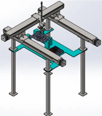
Fig. 7: The final 3TR Cartesian robot structure
Following these criteria, the CKK-110-NN-1 type of linear axis system with mounted motor from Bosch Rexroth was chosen. The linear axis has ball rail system guideway and a maximum travel of 840 mm, max. acceleration of 50 m/s2 and max. perm. torque of 13 Nm [9].
We used two synchronized motored linear systems on X axis for better stability of the mechanism and one for the Y axes; the one from Y axes is attached to the ones from X axes through two Z-shaped flanges (Figure 6).
The command and control system is based on an Arduiono ATMega 2560 controller (drivers for motors supplied by Boasch-Rexroth). The griping force sensors were acquired sparely. The design of the end effector is particular to the parts are to be manipulated.
In figure 7 is represented the final mechanism with motors and cylinder that performs the needed translations and rotation movements. The end-effector is an electric gripper especially designed to handle car fuses. It is powered by two electric servomotors, one for closing and opening the claws and the other for a complete 360° rotation for the fuse setting.
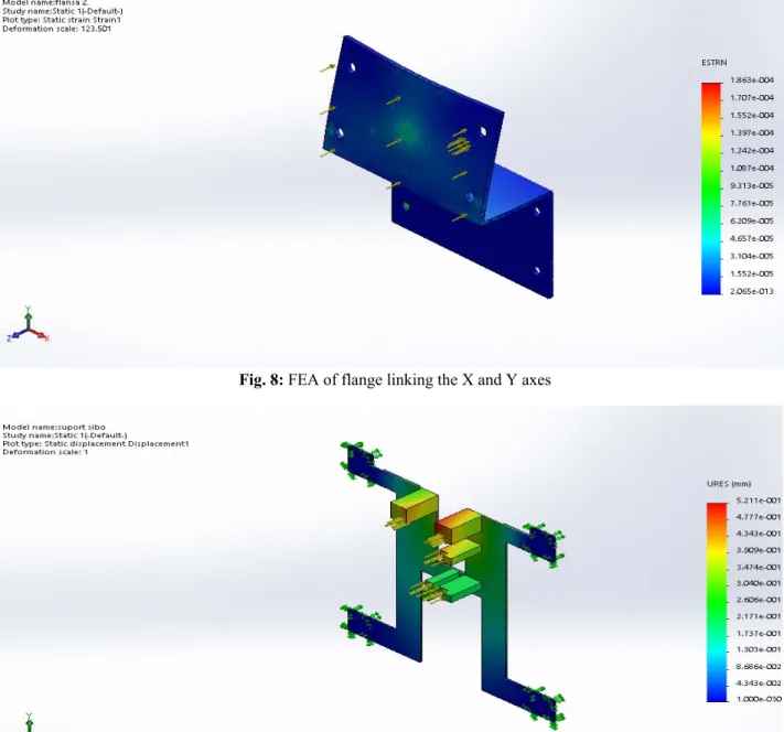
Finite element analyzes was performed to check the structure of the automated system and to observe the strength of the used parts and the degree of their deformation. A value of 10 mm deflection was considered acceptable. The model showed a 52.11 mm deflection. Thus, it was reinforced with one rib of 5 mm thickness.
Fig. 8: FEA of flange linking the X and Y axes
Fig. 9: Support board
3. CONCLUSIONS
This paper deals with the improving of the efficiency for a process of feeding a fuse box with auto fuses within an industrial enterprise,
by replacing the human operator with a 3TR Cartesian robot type.
reduce the number of damaged fuses, increase productivity due to the decrease of the fuses feeding time and eliminate errors caused by the human operator.
Finite element analyzes were performed in order to observe the strength of the used parts of the assembly and the degree of their deformation.
6. REFERENCES
[1] Kurfess, Thomas R., Robotics and Automation Handbook, Taylor & Francis, (2005).
[2] https://web.archive.org/web/201301230233 43/http://capek.misto.cz/english/robot.html, Retrieved June 2018.
[3] http://www.davidbuckley.net/DB/HistoryM akers.htm, Retrieved July 2018.
[4]
https://www.robotics.org/joseph-engelberger/unimate.cfm, Retrieved June 2018.
[5] http://my.ilstu.edu/~kldevin/Introduction_to _robotics2/Introduction_to_robotics6.html, Retrieved July 2018.
[6] Dragomir, M., Bodi, S., Iamandi, O. and Dragomir D., Aplying Sigmaflow simulation software for improving the quality of an R&D project, 2014 International Conference on Production Research – Regional Conference Africa, Europe and the Middle East 3rd International Conference on Quality and Innovation in Engineering and Management, July 1-5, 2014, Cluj-Napoca, Romania.
[7] Codre, C., Popescu, S., Constantinescu, C., Popescu, D., PLM As A Success Factor Of Sustainable Development, Proceedings of the 1st RMEE (Review of Management and Economic Engineering) Management Conference: Twenty Years After – How Management Theory Works, pp. 378-389, Cluj-Napoca, Romania (2010).
[8] https://www.carbuildersolutions.com/uk/cbs -12-circuit-wiring-module, Retrieved July 2018.
[9]
http://www13.boschrexroth-us.com/Catalogs/COMPACT_MODULES_ CKK.pdf, Retrieved June 2018.
SISTEM AUTOMATIZAT PENTRU POPULARE CU SIGURANŢE AUTO
Rezumat: Obiectivul principal al acestei lucrări a fost de a proiecta și de a realiza un sistem automatizat pentru popularea unei cutii de siguranțe cu siguranțe auto din cadrul unei intreprinderi industriale. Datorita faptului ca actualmente acest proces de populare cu sigurante este efectuat de catre un muncitor, se doreste ca prin intermediul acestui sistem sa se realizeze o scadere a numărului de siguranțe deteriorate, o reducere semnificativa a timpului de asamblare a acestora si reducerea erorilor cauzate de factorul uman. Pentru a atinge acest scop, studiul a fost axat pe proiectarea unui mecanism cat mai simplu, ieftin, ușor de utilizat si de realizat, pentru a putea fi ușor de implementat în cadrul companiei industriale. Pentru modelarea conceptului s-a utilizat software-ul SolidWorks 2016 iar pentru calculele intreprinse a fost folosit software-ul MathCad. Conceptul folosit este unul de tip robot cartezian care se potrivește cel mai bine cerințelor. Metoda Six Sigma a fost utilizată în etapa de dezvoltare a produsului și s-a efectuat analiza cu element finit pentru a verifica structura elementelor sistemului automatizat și pentru a observa rezistența pieselor utilizate, respectiv gradul de deformare a acestora.
Răzvan CURTA, Lecturer Eng., PhD, Technical University of Cluj-Napoca – Department of Design Engineering and Robotics, [email protected].
Mihai STEOPAN, Lecturer Eng., PhD, Technical University of Cluj-Napoca – Department of Design Engineering and Robotics, [email protected]..
Claudiu SCHONSTEIN, Lecturer Eng., PhD,, Technical University of Cluj-Napoca – Department of Design Engineering and Robotics, [email protected]
![Fig. 1: Unimate robot pouring coffee 1967 [5]](https://thumb-us.123doks.com/thumbv2/123dok_us/7996218.2120340/1.892.106.446.780.1140/fig-unimate-robot-pouring-coffee.webp)
![Fig. 3: The car fuse box [8]](https://thumb-us.123doks.com/thumbv2/123dok_us/7996218.2120340/3.892.496.821.848.1128/fig-the-car-fuse-box.webp)